1
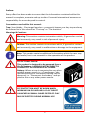
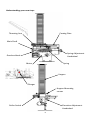
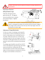
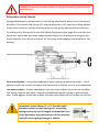
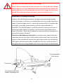
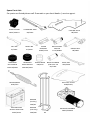
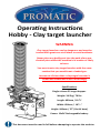
Operating Instructions
Hobby - Clay target launcher
WARNING
Clay target launchers can be dangerous and must be
treated with great care at all times to avoid accidents.
Never place any bodily part into the path of any mechanical piece whilst the machine is in motion or likely
to be so.
You must treat a clay target launcher with the same
caution that you would treat a loaded gun.
Assume at all times that a clay target launcher is
armed and loaded and treat it accordingly
Specifications:
Single column 55 target hopper.
Weight: 34.5kg / 76 lbs
Length: 490mm / 19 ¼“
Width: 420mm / 16 ½ “
Height: 940mm / 37” (On tilt base)
Power: 12vDC Rechargeable battery
This document must be read in full before attempting to operate the machine
Preface:
Every effort has been made to ensure that the information contained within this
manual is complete, accurate and up-to-date. Promatic International assumes no
responsibility for errors beyond its control.
Conventions used within this manual:
Trap: Your Hobby - Clay target launcher—commonly known as a clay trap and may
be referred to in this manual as “The trap” or “The machine”
Warnings & Cautions:
Warning: This section contains instructions which, if ignored or carried
out incorrectly, may result in risk of personal injury.
Caution: This section contains instructions which, if ignored or carried
out incorrectly, may result in malfunction or damage to the equipment
Note: This section contains additional information which the user may
find useful, but is not essential to the operation of the product.
12v DC Power Source:
This product is designed to be powered from a
12v DC battery, it SHOULD NOT BE DIRECTLY
CONNECTED TO HOUSEHOLD AC POWER
Battery: Where a trap is connected to any other
suitable power source i.e. a Transformer - the
relevant sections of instructions should still be
observed, i.e. “Disconnect the battery” and applied to this or any other power source.
EYE PROTECTION MUST BE WORN WHEN
WORKING ON OR AROUND A CLAY TARGET
LAUNCHER AS SMALL SHARP PIECES OF CLAY
MAY BE EJECTED DURING NORMAL USE.
2
Understanding your new trap:
Throwing Arm
Casting Plate
Main Shaft
Spring Adjustment
Handwheel
Gearbox block
Spring
Motor
Hopper
Plunger
Hopper Mounting
screws
Elevation Adjustment
Handwheel
Roller Switch
3
Connecting the battery:
Ensure you are behind the machine, the ARM/DISARM switch is in the OFF position
and it is otherwise safe to proceed. Connect the red cable to the Red (+) terminal
and the black cable to the Black (-) Terminal. Ensure the terminal fasteners are
tight, the battery is securely strapped to its tray and the charger has been removed.
Never approach the machine from the front or sides, Do not assume
the trap is safe even without electrical power it may still be armed.
Electrical Troubleshooting :
Trap fails to re-arm - after a period of prolonged use the trap fails to re-arm itself
and is found to be stalled (may also be making a humming sound) then this is an
indication that the battery is depleted, and the voltage has fallen too low to operate the trap. Disconnect the battery immediately and re-charge (or fit a replacement fully-charged battery).
Although the battery may appear to have recovered, the trap should not be used
any further than necessary to make it safe as this may cause damage to the motor,
Battery or other electrical circuits.
Trap fires by itself - Disconnect any external cable and switch the trap back on. If
the trap arms normally then the command cable is faulty. If the trap continues to
fire, switch the machine off and disconnect the battery. Check the roller switch is
moving freely and an audible click can be heard when it is moved. Re-test the machine. If the machine still fires by itself then the Roller switch is faulty and must be
replaced.
Circuit breaker has operated - The battery may have been incorrectly fitted
(terminals reversed) or an excessive amount of current was drawn either due to a
fault or obstruction within the trap.
If the circuit breaker has tripped due to an obstruction DO NOT ASSUME THE TRAP IS SAFE it may still be armed with the obstruction
holding back the energy from the spring - carefully clear the obstruction whilst remaining in the safe area behind the trap BE AWARE of
the path of the throwing arm AND the debris that may be ejected.
4
Positioning the machine
1.
2.
3.
Clay Target Launchers must be situated on firm level ground in a position that
will allow unrestricted access to rear of machine.
There must be no obstructions to the path of the throwing arm.
Ensure that the power supply can be easily disconnected and cables cannot
become tangled in any part of the mechanism.
Firing the machine
1.
2.
3.
Turn the ON/OFF or
switch (if fitted) to the ON or
position and set
the ARM/DISARM switch to the ARM/LOAD position. The machine will
move automatically and arm itself ready to launch a loaded clay.
Press the FIRE button on the command cable to throw a clay.
The machine will fire every time the FIRE button is pressed and will automatically rearm itself, until disarmed and switched off or disconnected.
Disarming the machine
1.
2.
To disarm the machine push the ARM/DISARM switch upwards to the DISARM position and immediately release (long enough for the trap to fire, but
not giving the machine a chance to rearm).
Turn the ON/OFF or
switch (if fitted) to the ON or
position and disconnect the battery.
Ensure the machine is stable on firm level ground before use.
Bolt the machine to a solid base or the Optional Trolley Base.
ALWAYS disarm the machine before any loading, adjustment or maintenance.
ALWAYS load clays from rear and ONLY if the machine is disarmed and safe.
NEVER approach the machine from the front or sides. ALWAYS from the rear.
NEVER allow children or untrained persons to approach or touch the machine.
NEVER move an armed/loaded machine. ALWAYS disarm and disconnect battery.
REMOVE the main throwing spring before Transport in a vehicle.
BE AWARE of the fall zone of both broken and unbroken clays and that a change in
wind direction will affect this.
5
Safe Mode Procedure - Warning: Stand at rear of machine only
1. Disarm the machine by flicking the ARM/DISARM switch upwards towards the
DISARM position and immediately releasing (long enough for the trap to fire, but
not giving the machine a chance to rearm). The Gearbox block (A rectangular
block attached to the gearbox shaft) should stop in a position pointing towards
the front of the machine.
2. If the Gearbox block is pointing directly towards the front of the machine, push
the ARM/DISARM switch momentarily in direction of DISARM/NUDGE just
enough to allow the block past its forward pointing position.
3. If the block has gone too far, rearm the machine and then disarm again until
the desired position is achieved.
4. Disconnect the battery/power source from the machine once the block is in
the correct position.
5. With the Gearbox block now pointing just past the forward pointing position,
the throwing arm can be pushed slowly, USING THE PALM OF THE HAND ONLY,
around counter clockwise .
6. As the throwing arm gets to the firing position (pointing direct to the back of
the machine) the spring will take over, at which point the drive bolt on the Gearbox block stops the arm, and prevents it from firing.
This is SAFE MODE the arm is now trapped between the drive bolt in one direction and locked on the one-way bearing within the trap, it cannot move or release again until power is applied and the ARM/DISARM switch operated.
6
ALWAYS disarm the machine before carrying out loading, adjustment or
maintenance.
Adjustment: Elevation
Setting Elevation angle
Trajectory of clays are from
approximately 26 - 50 degrees.
Loosen handwheel nut as shown,
tilt to desired angle, re-tighten
handwheel .
Be aware that if machine is already tilted upwards, when the handwheel is subsequently undone the machine will jolt forward. Support
the weight of the machine from the top of the clay hopper when adjusting the elevation angle.
Adjustment: Plunger Mechanism
As the arm rotates, the plunger presses gently
on the outer rim of the remaining clay stack to
hold it as the bottom clay is released from the
iris plates. With the trap at rest and the clays
pushed towards the two rear hopper rods there
should be a visible gap between the second clay
up in the stack and the red polyurethane plunger tip.
The plunger gap should be around 2mm (1/16")
and can be adjusted if required using two 10mm
spanners/wrenches. Holding the half nut
(located against the back of the brass plunger)
adjust the rear locking nut clockwise to increase
the gap or anti-clockwise to decrease it.
7
ALWAYS disarm the machine before carrying out loading, adjustment or
maintenance.
Adjustment: Spring Tension
Spring adjustment is always easier if the spring attachment point is at its rearmost
position, this relieves the spring of a large proportion of it’s tension making adjustment much easier as well as reducing wear on the spring adjustment mechanism.
To achieve this, first perform the Safe Mode Procedure (see page 6) to put the machine into safe mode and then nudge forward until the throwing arm projects forward from the front of the machine. At this point stop nudging and disconnect the
battery.
Decrease tension—Using the handwheel loosen spring to desired position. Hand
tighten inside nut to back of frame and clamp with a further turn of the handwheel.
Increase tension—Loosen handwheel one turn, then adjust the inner nut to allow
the spring room to pull back. Using the handwheel tighten spring to desired position. Hand tighten inside nut to back of frame and clamp with a further turn of the
Important: leave 30mm (1 3/16”) thread length
between inside nut and spring coil. Increasing
spring tension up to full length of thread will seriously detriment the performance of the machine
and will cause spring damage or failure.
8
WARNING BEFORE ADJUSTMENT (Arm timing)
Part of this procedure requires you to work very close to the trap - before
proceeding be sure you understand and have practised the procedure for
putting the trap into safe mode (this can be found on page 6 of this manual) and fully understand when the trap is safe and when it is not.
Adjustment: Throwing arm timing
Perform the Safe Mode Procedure, Using the Disarm/Nudge button
move the motor crank arm to a position just past the straight ahead position. If the block goes too far, rearm the machine (fire it) and then disarm again, repeating the procedure until the desired position is
achieved. (The ideal position is such that when the spring crank arm is
pointing straight ahead, the motor crank prevents any further movement of the arm.) Push the Throwing arm around until the spring crank
arm points directly forward.
Disconnect the battery at this point. Loosen the arm clamp block and
rotate the arm so the front of the yellow friction strip lines up with the
centre of the second bolt head on the gull wing bracket (on the Merlin)
(The right hand bolt head when viewed from the rear of the machine)
Re-tighten the arm clamp block firmly. Your trap is now correctly timed.
Timing position
(Over bolt)
Crank arm
Arm clamp block bolt
(under throwing arm)
9
Spare Parts List:
For parts not listed please call Promatic or you local dealer / service agent.
THROWING ARM
HB/2010
PLASTIC KNOB
D01V/100513
LEFT IRIS
EL/3550
HARDENED
IRIS LINKSGE
CAM HB/3625
UPPER
BACKRAIL
A28A/CUTO
RIGHT IRIS
EL/3600
HARDENED
ARM LINKAGE
CAM HB/2405
CASTING PLATE
HB/3100
ROLLER LIMIT
SWITCH
E11V/83850
SPRING BUSH BRASS PLUNGER
C/W SOFT TIP
HB/2635
HK/1200
MAIN SPRING
S01Z/FFLY
MAIN SHAFT
HB/2600
BACK RAIL
HR2/3440
SOFT FALL PLATE
A28S/PAFQ
HOPPER
(UK clay)
CAR/B9
BATTERY 22Ah
SEALED AGM TYPE
E30V/SLC22
HOPPER
(USA clay)
CAR/B10
10
MOTOR & GEARBOX
M01V/50492E
11
Promatic International Ltd.
Station Works,
Hooton,
South Wirral
CH66 7NF,
United Kingdom.
Tel: +44 (0) 151 327 2220 (General)
+44 (0) 1407 860800 (Sales)
Fax: +44 (0) 151 3277075
E-mail [email protected]
Website: www.promatic.co.uk
Promatic Inc.
7803 West Hwy 116
Gower
MO 64454
USA.
Toll Free: 888.767.2529
Fax: 816.539.0257
E-mail: [email protected]
Website: www.promatic.biz
Hobby Version
121.4 July 2013