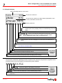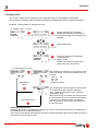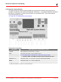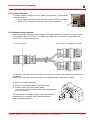
1
Operating Instructions Lambdatronic P 3200 for Fröling Pellet Boiler P4 Pellet (from Version 50.04 - Build 04.11) Be sure to read and comply with the operating instructions and safety information Subject to change Fröling Heizkessel- und Behälterbau Ges.m.b.H Tel +43 (0) 7248 606-0 Fax +43 (0) 7248 606-600 Industriestraße 12 [email protected] A-4710 Grieskirchen www.froeling.com C Contents 1 General 5 1.1 About this introduction 5 1.2 Safety Information 5 1.3 Before switching on for the first time 6 1.3.1 Lambdatronic Check ............................................................................................................6 1.3.2 Check the connected units ...................................................................................................6 1.3.3 System Check ......................................................................................................................6 2 Overview of the Basic Functions 7 2.1 Control Keys and Display 7 2.1.1 Navigation Keys ...................................................................................................................7 2.1.2 Status LED ...........................................................................................................................7 2.1.3 Function Keys.......................................................................................................................8 Info Key ............................................................................................................................................9 2.1.4 Graphic display...................................................................................................................10 2.2 Operating statuses 3 Operation 11 12 3.1 Initial startup 12 3.1.1 Changing the Operating Level............................................................................................12 3.1.2 Setting the System Type ....................................................................................................13 1. Boiler Type .................................................................................................................................13 2. System selection ........................................................................................................................14 3. Hydraulic System .......................................................................................................................14 3.1.3 Before heating up for the first time .....................................................................................14 Drives .............................................................................................................................................14 Check sensors................................................................................................................................15 Setting sensor “Level Max” ............................................................................................................15 3.2 Starting the system 16 3.2.1 Feeding fuel into the combustion chamber ........................................................................16 3.2.2 Start boiler ..........................................................................................................................16 Automatic mode .............................................................................................................................16 Modes in automatic mode ..............................................................................................................16 Summer mode................................................................................................................................17 3.3 Setting parameters 17 3.4 Setting times 18 Clearing the time window: ...........................................................................................................18 4 Menu Overview and Parameters 19 4.1 Menu - Heating 20 4.1.1 Status Displays for the Heating Circuits .............................................................................20 4.1.2 Temperature settings for the heating circuits .....................................................................20 4.1.3 Heating times of the heating circuits ..................................................................................21 4.1.4 Service parameters for heating circuit................................................................................21 4.2 Menu - Water 22 4.2.1 Status Displays for the DHW Tank.....................................................................................22 Page 2 B 037 05 08_en v C Contents 4.2.2 Temperature settings of the DHW tank..............................................................................22 4.2.3 Heating times of the DHW tank..........................................................................................23 4.2.4 Service parameters of the DHW tank.................................................................................23 4.3 Menu - Solar 24 4.3.1 Status displays for the solar system...................................................................................24 4.3.2 Temperature settings for the solar system.........................................................................24 4.3.3 Service parameters for Solar System ................................................................................25 4.4 Menu - Storage tank 26 4.4.1 Status display of the storage tank ......................................................................................26 4.4.2 Temperature settings for storage tanks .............................................................................26 4.4.3 Heating times of the storage tank ......................................................................................26 4.4.4 Service Parameters for Storage Tank................................................................................27 4.5 Menu - Boiler 28 4.5.1 Status Displays for the Boiler .............................................................................................28 4.5.2 Temperature Settings for the Boiler ...................................................................................28 4.5.3 Service parameters of the boiler ........................................................................................29 4.6 Menu - Boiler 2 30 4.6.1 Status Displays for the Secondary Boiler...........................................................................30 4.6.2 Temperature Settings for the Secondary Boiler .................................................................30 4.6.3 Service Parameters for Secondary Boiler ..........................................................................31 4.7 Menu - Pellets 31 4.7.1 Fuel Filling Times ...............................................................................................................31 4.7.2 Service Parameters for Fuel Feed .....................................................................................31 4.8 Menu - Network pump 32 4.8.1 Network Pump Status Displays..........................................................................................32 4.8.2 Network pump temperature settings ..................................................................................32 4.8.3 Service parameters for the network pump .........................................................................33 4.9 Menu - Difference regulator (Differential temperature regulating output) 34 4.9.1 Status displays for the difference regulator........................................................................34 4.9.2 Temperature settings for the difference regulator ..............................................................34 4.9.3 Service Parameters for the Difference Regulator ..............................................................35 4.10 Menu - Circulation pump 36 4.10.1 Status displays for the circulation pump...........................................................................36 4.10.2 Temperature settings for the circulation pump.................................................................36 4.10.3 Time setting for the circulation pump ...............................................................................37 4.10.4 Service parameters of the circulation pump.....................................................................37 4.11 Menu - Manual 38 4.11.1 Manual operation .............................................................................................................38 4.11.2 Digital Outputs..................................................................................................................38 4.11.3 Analogue Outputs ............................................................................................................39 4.11.4 Digital Inputs ....................................................................................................................40 4.12 Menu - System 41 4.12.1 Adjustable parameters .....................................................................................................41 Adjustable Parameters - Boiler Temperature ................................................................................ 41 Industriestraße 12 A-4710 Grieskirchen Fröling Heizkessel- und Behälterbau Ges.m.b.H Tel +43 (0) 7248 606-0 Fax +43 (0) 7248 606-600 [email protected] www.froeling.com Page 3 B 037 05 08_en C Contents Adjustable Parameters - Flue Gas .................................................................................................41 Adjustable Parameters - Ignition ....................................................................................................42 Adjustable Parameters - Air Settings .............................................................................................42 Adjustable Parameters - Pellet loading..........................................................................................43 Adjustable Parameters - Chamber Delivery Unit ...........................................................................43 Adjustable Parameters - Lambda Values ......................................................................................44 General Settings ............................................................................................................................44 4.12.2 Current system values......................................................................................................45 4.12.3 Error list ............................................................................................................................45 4.12.4 Parameters for sensors and pumps .................................................................................46 4.12.5 Operating rights and allocations for displays....................................................................46 4.12.6 Basic display parameters .................................................................................................47 4.12.7 Set mode ..........................................................................................................................47 4.12.8 Language Settings ...........................................................................................................47 4.12.9 Time settings ....................................................................................................................47 4.12.10 Standard settings ...........................................................................................................48 4.12.11 Current User Level .........................................................................................................48 4.12.12 System parameters ........................................................................................................48 4.13 Boiler Type-Related Factory Settings 48 5 Troubleshooting 49 5.1 Error display 49 6 Electrical Connection and Wiring 50 6.1 Core module 50 6.1.1 Connection instructions ......................................................................................................50 6.1.2 Mains connection ...............................................................................................................51 6.1.3 Connecting the Flue Gas Sensor .......................................................................................51 6.1.4 Combination with Oil Burner...............................................................................................52 6.1.5 Connecting the remote control ...........................................................................................52 6.1.6 Boiler release input.............................................................................................................53 6.1.7 Error message switch.........................................................................................................53 6.2 Expansion modules 54 6.2.1 Heating circuit module........................................................................................................54 Connection instructions..................................................................................................................54 6.2.2 Hydraulic System Module...................................................................................................55 Connection instructions..................................................................................................................55 6.2.3 Pellet module......................................................................................................................56 Connection instructions..................................................................................................................56 6.2.4 Pellet Module Expansion....................................................................................................57 Connection instructions..................................................................................................................57 6.2.5 Connecting the bus cable...................................................................................................58 6.2.6 Setting the module address................................................................................................58 6.2.7 Setting end jumper .............................................................................................................59 6.3 Universal suction system 59 7 Setting protocol 60 8 Index Directory 62 Page 4 B 037 05 08_en v 1 General Dear customer, Please read and observe the operating instructions, particularly the safety information, and always keep them close by the boiler for reference. 1 General 1.1 About this introduction These operating instructions include important information about operation, electrical connection and troubleshooting for the Lambdatronic P 3200. All parameters, which are visible at the customer operator level and service technician operator level, are shown. The constant further development of our products means that there may be minor differences from the pictures and content. If you discover any errors, please let us know. Subject to technical change. 1.2 Safety Information CAUTION Do not touch hot surfaces and flue gas pipes! Burns hazard! Before carrying out work on/in the boiler: Shut down the boiler in a controlled way with the service key and wait until it reaches the status “Burner OFF” and the boiler has cooled down CAUTION Working on electrical components. Risk of injury from electric shock! Work on electrical components should be carried out by authorised professionals. Observe all applicable standards and regulations! Work on electrical components by unauthorised personnel is absolutely forbidden! The information on safety, standards and guidelines in the operating instructions for the boiler should also be observed. Industriestraße 12 A-4710 Grieskirchen Fröling Heizkessel- und Behälterbau Ges.m.b.H Tel +43 (0) 7248 606-0 Fax +43 (0) 7248 606-600 [email protected] www.froeling.com Page 5 B 037 05 08_en 1 General 1.3 Before switching on for the first time NOTICE You should have the initial startup carried out by the authorised professional from Fröling customer services. 1.3.1 Lambdatronic Check Check boards for foreign bodies (pieces of wire, washers, screws) Carry out wiring check: Check for loose, uninsulated wires, which could cause a short-circuit Check plug arrangement of pumps, mixers and other units, which have NOT been prepared by Fröling Check the connection of the BUS cable for short-circuits Check the specified addresses and terminal jumper on the individual modules (heating circuit modules, hydraulic modules, displays,…) 1.3.2 Check the connected units Check that all units that are used are connected correctly Carry out wiring check: Check for loose or uninsulated wires in the terminal boxes of the pumps, mixers and switch valve, which could cause a short-circuit 1.3.3 System Check Check that the main fuse for the boiler has a sufficient rated amperage (16A) If a safety overload switch is used, it should be a type with 16A and “Tripping Characteristic C”. Page 6 B 037 05 08_en v 2 Basic Configuration of the Lambdatronic P 3200 Keys, Display and Operating Statuses 2 Overview of the Basic Functions 2.1 Control Keys and Display Function Keys (2.1.3) Graphical Display (2.1.4) Navigation Keys (2.1.1) Status LED (2.1.2) 2.1.1 Navigation Keys The navigation keys are for moving around the menu and changing parameter values. Key Function with Navigation: Move up in the menu Parameter change: UP arrow Short keystroke: Increase value Long keystroke: Increase value in steps of 10 Long keystroke (> 10 sec): Increase value in steps of 100 Navigation: Move down in the menu Parameter change: DOWN arrow Short keystroke: Decrease value Long keystroke: Decrease value in steps of 10 Long keystroke (> 10 sec): Decrease value in steps of 100 Navigation: Go to selected menu Parameter change: Enter key Short keystroke: Unlock parameter for editing or save parameter value Navigation: Go back to higher menu Parameter change: Back key Short keystroke: Do not save parameter value Long keystroke: Back to basic display without saving 2.1.2 Status LED The status LED shows the operating status of the system: - green flashing light: BOILER ACTIVE - flashing red light: WARNING or FAULT Industriestraße 12 A-4710 Grieskirchen Fröling Heizkessel- und Behälterbau Ges.m.b.H Tel +43 (0) 7248 606-0 Fax +43 (0) 7248 606-600 [email protected] www.froeling.com Page 7 B 037 05 08_en 2 Basic Configuration of the Lambdatronic P 3200 Keys, Display and Operating Statuses 2.1.3 Function Keys The function keys of the Lambdatronic P 3200 have dual functions. Different functions can be called with long or short keystrokes, using the following definitions of keystroke duration: Short keystroke ........ < 1 sec Long keystroke ........ > 4 sec Keystroke Service Program Automatic program Function / Symbol in status line Short Chimney-sweep mode Long Service mode Control follows the boiler shutdown procedure and after the cleaning cycle the grate stays in open position. The ID fan runs at controlled speed and the door contact switch is activated. Recommended for ash discharge Short Automatic mode (mode) Heating circuits and domestic hot water are controlled according to the programs and times set. Long Off The control follows the boiler shutdown procedure and starts with the cleaning cycle. After the cleaning cycle the boiler goes to “Burner Off” status. The Lambdatronic controls the connected heating components. All parts of the boiler are deactivated. Short Party mode Only with room console! After an optional change to the room temperature set value the control of the heating circuits stays in heating mode until the end of the next heating time or until activation of the automatic mode. Function not possible in summer mode! Long Extra heating Heating and domestic hot water are heated for 6 hours The mode set is ignored. Caution: External temperature heating limit active! Short Display info text Long No function Query / Clear text information on menu points or errors. Page 9, “Info Key“ Short Extra loading Long Summer mode Domestic hot water loading according to specified program, heating circuits are deactivated. Caution: No frost protection! Short Setback mode Only with room console! After an optional change to the setback temperature the control of the heating circuits remains in setback mode until the start of the next heating time or until activation of another mode. Long Continuous setback Party program Info DHW tank program Setback program Page 8 B 037 05 08_en System is operated for 30 mins with rated load Manual loading of domestic hot water. Only with room console! The room temperature is reduced to the preset setback temperature until automatic mode is activated. v 2 Basic Configuration of the Lambdatronic P 3200 Keys, Display and Operating Statuses Info Key The info key can be pressed at any time and always shows information about the current menu item or the current fault message, with fault messages occupying the highest priority. Info key in normal mode: In normal mode (without faults) the info key can be pressed to display information or an explanation for every menu point or parameter. The info text is also identified by the frame and the info symbol in the symbol tab. Info key for pending warning or fault: If a fault was acknowledged after arising, but not resolved, this is displayed by a warning symbol at the bottom right on the symbol tab. Pressing the info key calls up the information on the currently pending fault message again. Procedure for troubleshooting: Page 49, Troubleshooting Industriestraße 12 A-4710 Grieskirchen Fröling Heizkessel- und Behälterbau Ges.m.b.H Tel +43 (0) 7248 606-0 Fax +43 (0) 7248 606-600 [email protected] www.froeling.com Page 9 B 037 05 08_en 2 Basic Configuration of the Lambdatronic P 3200 Keys, Display and Operating Statuses 2.1.4 Graphic display Shows operating status or menu name Shows the current time Shows the main values in the basic display (adjustable), menu content, parameters and info texts Status symbol line ... Shown when a problem (warning / fault / error) is pending. Pressing the info key displays texts for troubleshooting errors and faults. / ... ... / / / ... Shows the storage tank loading status (storage tank is optional) ... This is displayed when the cleaning program has been started. Key for starting the function, see 2.1.3 Function Keys Indicates that an info text is displayed. Info texts are also identified by a frame. Shows which function is active See 2.1.3 Function Keys ... shows that the DHW tank pump is active ... shows that the storage tank pump is active ... Shows that the heating circuit pump of the 2nd heating circuit is active Only shown in the basic display. ... Shows that the heating circuit pump of the 1st heating circuit is active At the service technician operating level the function of the relevant components is signalled in the individual status menus through the corresponding status display: / / / / ... Shows the status of the heating circuit mixer ... Shown when the heating circuit or storage tank pump is active ... Shown when the DHW tank or return feed lift pump is active ... Shows whether the storage tank (or oil boiler) is hot enough for hot water preparation Page 10 B 037 05 08_en Only for service technicians in the status menus v 2 Basic Configuration of the Lambdatronic P 3200 Keys, Display and Operating Statuses 2.2 Operating statuses There are 12 different boiler statuses, which are shown at the top left of the graphic display: Preparation The boiler is ventilated, the sealing slider is opened and the Lambda probe is heated. Heating up The combustion chamber is filled with pellets. Pre-heating The fan-assisted ignition switches on and the pellets are preheated until a bed of embers is formed. For this period loading is deactivated. Ignition The pellets are ignited with the fan-assisted ignition. The flame is distributed around the whole combustion chamber. The control of the loading unit is defined as “Ignition” in the parameter menu. Heating The Lambdatronic controls combustion according to the boiler setpoints. Constant burn The boiler has no power consumption. The ID fan and the loading unit are deactivated. Cleaning The Lambdatronic carries out the cleaning program (duration approx. 3 min). The grate and heat exchanger are cleaned. Shutdown wait When the boiler is interrupted during the heating up procedures (heating up, pre-heating, ignition), it waits for a specified period of time until the next start attempt. Shutdown wait 1 The ID fan runs to burn the remaining pellets. The loading unit is deactivated. Shutdown wait 2 The system is still ventilated by chimney draught. The loading unit is deactivated. Fault CAUTION - Fault persists! Procedure see page Chapter 5 - Troubleshooting Burner Off The Lambdatronic controls the connected heating components. All parts of the boiler are deactivated. Industriestraße 12 A-4710 Grieskirchen Fröling Heizkessel- und Behälterbau Ges.m.b.H Tel +43 (0) 7248 606-0 Fax +43 (0) 7248 606-600 [email protected] www.froeling.com Page 11 B 037 05 08_en 3 Operation 3 Operation Before the initial startup check the wiring of the pumps and mixers is correct. See 1.3 Before switching on for the first time Check that the connected components have maximum connected load. See 6.1 Core module or 6.2 Expansion modules 3.1 Initial startup After power up the start logo is displayed. The control performs the system check. After the system check the basic display is shown. 3.1.1 Changing the Operating Level For safety reasons certain parameters are only visible at specific operating levels. To change to another level it is necessary to enter the relevant user code: repeatedly repeatedly ... Child lock (Code 0) At “Child lock” level, only the basic readout is displayed. It is not possible to change parameters at this level. Customer (Code 1) Standard level for normal operation of controls. All customer-specific parameters can be displayed and altered. Installer / Service Releases parameters to adjust controls to the system components. All the parameters shown in these operating instructions are available. Page 12 B 037 05 08_en v 3 Operation 3.1.2 Setting the System Type Only for trained personnel - the installer code must be entered! repeatedly ... 1. Boiler Type ... Boiler type - S4 Turbo : FHG Turbo 3000 20 DO NOT SELECT! : Pellet boiler P2 - 10 : P4 Pellet 8 - 25 SELECTED← - P4 boiler type: P4 Pellet 8 P4 Pellet 15 P4 Pellet 20 P4 Pellet 25 P4 Pellet 32 - 38 ← - P4 boiler type: P4 Pellet 32 P4 Pellet 38 Turbomatic : DO NOT DIAL! Wood boiler F2 22/30 Boiler type parameters: ... Lambda probe installed YES Boiler release - input installed NO Boiler stops automatically when no heat required NO Supply bin installed NO Vacuum screw filling system installed NO Universal suction, manually operated YES Universal suction, automatically operated Industriestraße 12 A-4710 Grieskirchen Fröling Heizkessel- und Behälterbau Ges.m.b.H Tel +43 (0) 7248 606-0 Fax +43 (0) 7248 606-600 [email protected] www.froeling.com NO Page 13 B 037 05 08_en 3 Operation 2. System selection ... System selection - Hydraulic System 0 Selected - SELECT Hydraulic system 1 For description see brochure “Lambdatronic P3200 Energy Systems” Hydraulic system 2 Hydraulic system 3 Hydraulic system for F2 Boiler Hydraulic System 12 DO NOT DIAL! - Hydraulic System 13 SELECT H3200 Variant 1 H3200 Variants 2 and 5 Multiple house schemes System Variants 1 to 5 H3200 Variant 3 H3200 Variant 4 3. Hydraulic System ... DHW tank system - DHW tank 01 installed Y/N : DHW tank 08 installed ... Heating system - Heating circuit 01 installed Remote control 01 installed Y/N Y/N Y/N : ... Solar system Heating circuit 18 installed Y/N Remote control 18 installed Y/N - Solar collector 01 installed Y/N 3.1.3 Before heating up for the first time Check the system pressure of the heating system Check that the heating system is completely vented Check if the safety devices are present and working correctly Checking to see whether there sufficient ventilation and venting of the boiler room is guaranteed. Check the seal of the boiler All doors and inspection openings must be tightly sealed! Drives Check that drives and servomotors are working and turning in the right direction Page 32, Analogue outputs and digital outputs Page 14 B 037 05 08_en v 3 Operation Check sensors Check the sensor shown below in the digital input menu: Page 32, Digital inputs Sensor Layout Description A 0 ... Door closed, switch activated A 1 ... Door open, switch not activated Set the switching point so that when an ash door is opened the ID fan runs. Jam sensor Jam sensor (N/O): A 0 ... Sensor not covered A 1 ... Sensor covered The jam sensor is used for suction systems with screw delivery and is mounted at the suction piece. The setting is the same as sensor “Level Max”. Max level Max level (opener): A 0 ... Sensor covered A 1 ... Sensor not covered Setting sensor “Level Max” Door contact Grate open Grate closed Grate open ... A 0 ... A 1 Grate closed Grate closed Grate open ... A 1 ... A 0 The two parameters must always be different. Setting sensor “Level Max” In delivery configuration, the factory settings of the sensor are secured with a seal. Changes to the settings should only be carried out by qualified technicians. 2 The monitoring LED (1) should only light up when identifying materials! 1 If the monitoring LED stays on permanently, the sensitivity is set too high! Reduce the sensitivity by turning the adjusting screw (2) to the left If the monitoring LED does not react when pellets are being fed in, the sensitivity is set too low! Increase the sensitivity of the adjusting screw by turning to the right Industriestraße 12 A-4710 Grieskirchen Fröling Heizkessel- und Behälterbau Ges.m.b.H Tel +43 (0) 7248 606-0 Fax +43 (0) 7248 606-600 [email protected] www.froeling.com Page 15 B 037 05 08_en 3 Operation 3.2 Starting the system 3.2.1 Feeding fuel into the combustion chamber At initial startup there are no pellets in the stoker: Set the parameter, “Manual filling of the pellet container” to ON The cyclone is filled with pellets, it switches off automatically at 100% fill level and sets the parameter back to OFF Set the parameter “Manual Feed to Combustion Chamber” to ON As soon as the first pellets fall into the combustion chamber set the parameter back to OFF Observe the process in the inspection window of the stoker screw If the parameter was reset too late and for this reason the grate is covered with pellets, this must be opened in manual operation so that the pellets can fall down, avoiding overfilling when the system starts and a possible flash fire. 3.2.2 Start boiler Automatic mode Press on the control Heating circuits and domestic hot water are controlled according to the programs and times set. The clock symbol is shown in the status line of the graphic display. repeatedly Modes in automatic mode repeatedly ... Winter mode The Lambdatronic controls the heating and hot water heating according to the specified timed program. The boiler is constantly regulated to the temperature setpoint. Transition mode without storage tank: As with winter mode, heat is only produced in up to four adjustable time windows. At the end of the time window the boiler follows the shutdown procedure and goes “Burner Off” status. Transition mode with storage tank: The boiler only creates heat during the specified storage times (Storage tank management). Heating and hot water are active. Summer mode The domestic hot water is prepared in the boiler loading times set. All heating circuits switched off. Page 16 B 037 05 08_en v 3 Operation Summer mode Press the key on the controls and hold it for 5 seconds The boiler only controls the hot water heating according to the timed program settings. There is no frost protection for the heating circuits The tap symbol is shown in the status line of the graphic display. For other modes press the relevant function key: Page 8, 2.1.3 Function Keys 3.3 Setting parameters Values for all parameters are changed in the following way: Save value and go back Unlock parameter for processing Larger Navigate to the desired parameter Smaller Back without saving For initial startup the following parameters should be checked and adjusted if required: - Heating curve: Radiator or underfloor heating The other parameters are factory set in such a way that in most cases optimal operation is possible without making further changes to the parameters. The following parameters, however, can/should be set as desired by the customer: - Desired boiler temperature setpoint - DHW tank loading times - Storage tank loading times - Solar system control - Heating and setback times of the individual heating circuits - Start of automatic filling of pellet container Industriestraße 12 A-4710 Grieskirchen Fröling Heizkessel- und Behälterbau Ges.m.b.H Tel +43 (0) 7248 606-0 Fax +43 (0) 7248 606-600 [email protected] www.froeling.com Page 17 B 037 05 08_en 3 Operation 3.4 Setting times The “Times” menu can be called up in the individual menus of the heating components. The structure of the time menu and the procedure for changing the times is always the same! Example - Setting times for heating circuit 01: In “Heating” menu -> “Times”: Current settings for the individual weekdays are displayed. Pressing the arrow keys changes to the next/previous weekday. See example below... The factory set times are loaded by confirming again. (06:00 - 22:00) Caution - the customer specific time settings are lost in the process! ... in “Change program” menu: Abort without saving Save and go back After pressing the enter key you can select the day or the time period, for which the heating times are to be set: - MO, TU, .., SU - MO - FR - SA - SU - SAME ALL DAYS After pressing the enter key again the time window for the desired day/time period is displayed. Up to 4 different heating times can be entered consecutively here. When the enter key is pressed, the cursor jumps to the next position, even if no time has been entered. If the cursor is in the last position, pressing the enter key saves the time window and switches to the previous menu. Clearing the time window: Changed the end time of the desired time window to 24:00. If you press the up arrow key repeatedly the time disappears and is replaced by dashes. Then carry out the same process with the start time. Repeatedly pressing the enter key takes you back to the previous menu saving the times. Page 18 B 037 05 08_en v 4 Menu Overview and Parameters 4 Menu Overview and Parameters Page 20, 4.1 Menu - Heating Page 22, 4.2 Menu - Water Page 24, 4.3 Menu - Solar Page 26, 4.4 Menu - Storage tank Page 28, 4.5 Menu - Boiler Page 30, 4.6 Menu - Boiler 22 Page 31, 4.7 Menu - Pellets Page 32, 4.8 Menu - Network pump Page 34, 4.9 Menu - Difference regulator Page 36, 4.10 Menu - Circulation pump Page 38, 4.11 Menu - Manuall Page 41, 4.12 Menu - Systemm Industriestraße 12 A-4710 Grieskirchen Fröling Heizkessel- und Behälterbau Ges.m.b.H Tel +43 (0) 7248 606-0 Fax +43 (0) 7248 606-600 [email protected] www.froeling.com Page 19 B 037 05 08_en 4 Menu Overview and Parameters 4.1 Menu - Heating 4.1.1 Status Displays for the Heating Circuits Heating Circuit 01 ... 18 Display Description No Æ Heating circuit is completely switched off No frost protection! Control heating circuit according to prog. YES Actual flow temperature 46°C Shows the current flow temperature. Flow temperature setpoint 52°C The calculated flow temperature setpoint. Room temperature 21°C Temperature on remote control of the current heating circuit (option). Override switch Auto Shows the current switch setting on the remote control (option) 1 = Party mode (Ä), the setback mode is ignored Setback = setback mode (e); heating mode is ignored Auto = Automatic mode (); heating/ setback mode according to heating times External temperature 2°C Shows the current external temperature. 4.1.2 Temperature settings for the heating circuits Heating Circuit 01 ... 18 Setting value Description 22°C Desired room temperature during setback mode 16°C Flow temperature SP at external temperature of +10°C 40°C Flow temperature SP at external temperature of -10°C 60°C For setting the desired room temperature for heating and setback mode. (Parameter only with optional remote control!) The heating curve to the relevant system can be adjusted with these two work points. Example of floor heating Flow tem erature Desired room temperature during heating mode Example of radiators External temperature Page 20 B 037 05 08_en v 4 Menu Overview and Parameters Setting value Description Controller gain room temperature Kp-Rm 6.0 Influencing factor of room temperature on the flow temperature of the heating circuit. If there is a deviation of the room temperature of ± 1°C the set value of the flow temperature is corrected by this value. (Parameter only with optional remote control!) Recommended values for - Floor heating 2–3 - Radiators (new build): 4 – 5 - Radiators (old build): 6–7 Notice: Observe external influences on the room sensors Reduction of flow temperature in setback mode 15°C The flow temperature is reduced by this value in the setback phase. External temperature, at which heating circuit pump switches off in heating mode 18°C If the external temperature exceeds this value during heating, the heating circuit pump and mixer are deactivated. External temperature, at which heating circuit pump switches off in setback mode If the external temperature falls below this value during setback mode, the heating circuit pump and mixer are activated. 7°C Maximum flow temperature 75°C Maximum temperature for limiting flow temperature. Frost protection temperature 10°C If the room temperature or the outfeed temperature is lower than the set value, the heating circuit pump will be switched on. Heating Circuit 01 ... 18 repeatedly 4.1.3 Heating times of the heating circuits Setting the time window see page 18, 3.4 Setting times Heating Circuit 01 ... 18 Parameter Description Heating circuit pump A0 Heating Circuit Mixer OPEN A0 Heating Circuit Mixer CLOSED A0 Mixer runtime repeatedly 4.1.4 Service parameters for heating circuit 240s Used for testing the individual outputs. Page 38, 4.11 Menu - Manual Set mixer runtime of heating circuit mixer in use. Should this heating circuit heat when there is DHW tank priority NO From which storage tank or distributor is the heating circuit supplied (0 = boiler) 1 Notice: Only valid for multiple house systems Allocation of the heat source for this heating circuit. For standard systems the parameter is left as 1 0 = Boiler, 1 = storage tank 01, ... Industriestraße 12 A-4710 Grieskirchen Fröling Heizkessel- und Behälterbau Ges.m.b.H Tel +43 (0) 7248 606-0 Fax +43 (0) 7248 606-600 [email protected] www.froeling.com Page 21 B 037 05 08_en 4 Menu Overview and Parameters 4.2 Menu - Water 4.2.1 Status Displays for the DHW Tank DHW tank 01 ... 08 Display DHW tank top temperature Description 60°C Current temperature in the top part of the DHW tank. The DHW tank is heated during the loading times until the specified parameter, “Desired DHW temperature”, is reached. DHW tank bottom temperature 55°C Current temperature in the lower part of the DHW tank. (parameter only available with solar element). DHW tank pump control Specifies the speed of the DHW tank pump as a percentage of maximum speed. 0% 4.2.2 Temperature settings of the DHW tank DHW tank 01 ... 08 Setting value Description Desired DHW tank temperature 60°C When the specified temperature is reached in the DHW tank, the DHW tank loading pump switches off. Reload if DHW tank temperature is below 45°C Reloading of the DHW tank is authorised when the DHW tank temperature is below this level. Load if temperature difference between storage tank and DHW tank is Load if temperature difference between boiler and DHW tank is When the storage tank top temperature is above the DHW tank temperature by this value, the DHW tank loading pump is released. 6°C 6°C Setpoint for temperature difference between boiler - DHW tank 10°C Initial value of DHW tank loading. The boiler temperature must be higher than the DHW tank temperature by this value so that the DHW tank loading process begins. Adjusting the boiler temperature setpoint to reach the desired DHW tank temperature. Boiler temperature setpoint = DHW tank temperature setpoint + Difference. If the boiler temperature setpoint is higher than the DHW temperature setpoint + difference, the boiler temperature setpoint is maintained. Page 22 B 037 05 08_en v 4 Menu Overview and Parameters DHW tank 01 ... 08 repeatedly 4.2.3 Heating times of the DHW tank Setting the time window see page 18, 3.4 Setting times DHW tank 01 ... 08 Parameter repeatedly 4.2.4 Service parameters of the DHW tank Description Residual heat use NO Function can only be used for systems without storage tank and in combination with bypass pump/ return feed mixer. Here the residual energy is diverted to the DHW tank, the parameter “Pumps start at” is ignored. The pump is controlled with minimum speed until the boiler temperature is lower than the DHW tank temperature + 3°C. Only load DHW tank once a day NO If this parameter is set to “YES”, repeated heating on one day is prevented. Legionella heating activated YES The DHW tank is heated once a week to at least 65°C. Which day for legionella heating MO Day of the week on which the Legionella heating is carried out. Which storage tank or heat distributor supplies the heat (0 = boiler) 1 When using several storage tanks or heat distributors, the storage tank or heat distributor for DHW tank loading is selected here. If only one storage tank or heat distributor is used, leave the parameter on the standard setting of 1. Notice: Only valid for multiple house systems Minimum DHW pump speed 45% Which sensor is used for top DHW tank 1 0.3 Which pump is used for DHW tank 1 0.2 Adjustment of the minimum speed to the pump type. Notice: Always set the pump to the highest power level. (only switch the pump when it is disconnected from the power supply) Parameter display depends on the system. See “Lambdatronic P3200 Energy Systems” Industriestraße 12 A-4710 Grieskirchen Fröling Heizkessel- und Behälterbau Ges.m.b.H Tel +43 (0) 7248 606-0 Fax +43 (0) 7248 606-600 [email protected] www.froeling.com Page 23 B 037 05 08_en 4 Menu Overview and Parameters 4.3 Menu - Solar 4.3.1 Status displays for the solar system Display Description Collector Temperature 80°C Solar temperature storage tank bottom 38°C Current temperature at collector. Current temperature at solar sensor in bottom storage tank. DHW tank bottom temperature 39°C Current temperature in the lower part of the DHW tank. Collector pump runtime 1h Specifies the runtime of the collector pump. Collector pump control 78% Specifies the speed of the collector pump as a percentage of maximum speed. 4.3.2 Temperature settings for the solar system Setting value Description DHW tank temperature setpoint during solar charging 75°C Up to this temperature the DHW tank is heated by the solar system. Temp differential to start collector pump 10°C The collector loading pump activates when the collector temperature exceeds the storage or DHW tank temperature by this value. Temp difference to stop collector pump 5°C The collector loading pump activates when the collector temperature exceeds the storage or DHW tank temperature by this value. Maximum storage tank bottom temperature during solar charging Page 24 B 037 05 08_en Maximum bottom storage tank temperature at which the collector pump is switched off (only with storage tank). 85°C v 4 Menu Overview and Parameters repeatedly 4.3.3 Service parameters for Solar System Parameter Solar system Description 1 System dependent parameter: Setting according to solar diagram. See “Lambdatronic P3200 Energy Systems” Adjusting the minimum speed to the relevant pump type. Notice: Always set the pump to the highest power level. (only switch the pump when it is disconnected from the power supply) Minimum collector pump speed 45% Collector pump control Kp value 1.00 Leave the value! Specifies the controller gain of the collector pump. Collector pump control Tn value 300s Leave the value! Specifies the reset time of the collector pump control. Which sensor is used for the solar collector 1.1 Which sensor is used for the storage tank reference 0.2 Which pump is used for the solar collector 1.1 Which pump is used for the solar switch valve 1.2 Invert isolating valve NO A PT1000 sensor is used as a solar sensor NO Bus addresses of the sensors used, depending on the system. See 6.2.6 Setting the module address See “Lambdatronic P3200 Energy Systems” Bus address of the pump used. See 6.2.6 Setting the module address See “Lambdatronic P3200 Energy Systems” For DHW tank loading through the collector, the switch valve is controlled with 230V. If the valve switches incorrectly, this parameter can be adjusted. Basic setting for the sensor type used: NO Standard solar sensor - Fröling YES Sensor PT1000 Industriestraße 12 A-4710 Grieskirchen Fröling Heizkessel- und Behälterbau Ges.m.b.H Tel +43 (0) 7248 606-0 Fax +43 (0) 7248 606-600 [email protected] www.froeling.com Page 25 B 037 05 08_en 4 Menu Overview and Parameters 4.4 Menu - Storage tank 4.4.1 Status display of the storage tank Storage tank 01 ... 08 Display Description Storage tank top temperature 55°C Current temperature at top storage tank sensor. Storage tank middle temperature 53°C Current temperature at middle storage tank sensor (depending on configuration). storage tank bottom temperature 50°C Pump control Current temperature at bottom storage tank sensor. 0% Specifies the speed of the storage tank pump as a percentage of maximum speed. 4.4.2 Temperature settings for storage tanks Storage tank 01 ... 08 Setting value Description Minimum value of storage tank top temperature for heating circuit release in combination with a storage tank. Heating circuit release from following storage tank temperature 30°C Top storage tank minimum temperature - startup point 65°C Storage tank fully loaded if temperature difference Between boiler and bottom storage tank If the top storage tank temperature falls below this value, the boiler starts. Requirement: boiler is released by storage tank times. From this temperature difference between the boiler temperature and the bottom storage tank temperature, storage tank loading is stopped. 10°C Storage tank 01 ... 08 repeatedly 4.4.3 Heating times of the storage tank Setting the time window see page 18, 3.4 Setting times Page 26 B 037 05 08_en v 4 Menu Overview and Parameters Storage tank 01 ... 08 Parameter repeatedly 4.4.4 Service Parameters for Storage Tank Description Minimum storage tank pump speed 45% Which sensor is used for storage tank top 0.1 Which sensor is used for bottom storage tank 0.2 Which pump is used for the storage tank 0.1 Adjustment of the minimum speed to the pump type. Notice: Always set the pump to the highest power level. (only switch the pump when it is disconnected from the power supply) Parameter display depends on the system. See “Lambdatronic P3200 Energy Systems” Industriestraße 12 A-4710 Grieskirchen Fröling Heizkessel- und Behälterbau Ges.m.b.H Tel +43 (0) 7248 606-0 Fax +43 (0) 7248 606-600 [email protected] www.froeling.com Page 27 B 037 05 08_en 4 Menu Overview and Parameters 4.5 Menu - Boiler 4.5.1 Status Displays for the Boiler Display Boiler temperature Description Display of the current values for the relevant parameter : : 70°C Flue gas temperature 176°C Flue gas setpoint 178°C Boiler control variable 95% ID fan control 75% ID fan speed 2350U Air speed at suction opening 0.00 m Ignition pipe temperature 0°C Calculated boiler setpoint 70°C Sensor 1 85°C 4.5.2 Temperature Settings for the Boiler Setting value Boiler temperature setpoint Shutdown if current boiler temperature is higher than boiler temperature setpoint + Always switch off above highest possible boiler temperature setpoint + Description 70°C If the boiler temperature exceeds the setpoint by this parameter value, the boiler switches to constant burn status. The boiler starts up again below the temperature setpoint. 15°C 3°C Minimum boiler temperature to release all pumps 35°C Page 28 B 037 05 08_en The boiler temperature is regulated to this value. (Range: 40 - 70 °C) Recommendation: System without storage tank 50°C, System with storage tank 70°C. If the boiler temperature exceeds the maximum setpoint by this parameter, the boiler switches to constant burn status. The heating circuit and store loading pumps will also begin to run to cool the boiler. The boiler starts up again below the temperature setpoint. The pumps are released at this boiler temperature. (Hysteresis 2°C). v 4 Menu Overview and Parameters Temperature in the STL housing at which all pumps run Heating circuit excess in variable mode If the temperature at the safety temperature limiter exceeds this value, all pumps are activated for heat emission. 80°C 2°C If variable mode is activated, the boiler setpoint temperature in heating mode is increased by this value compared to the required flow temperature. repeatedly 4.5.3 Service parameters of the boiler Parameter Variable mode activated Description NO The boiler temperature is controlled according to the calculated flow value for heating circuit/boiler. Industriestraße 12 A-4710 Grieskirchen Fröling Heizkessel- und Behälterbau Ges.m.b.H Tel +43 (0) 7248 606-0 Fax +43 (0) 7248 606-600 [email protected] www.froeling.com Page 29 B 037 05 08_en 4 Menu Overview and Parameters 4.6 Menu - Boiler 2 4.6.1 Status Displays for the Secondary Boiler Display Description Boiler temperature 80°C Burner relay status 0 Display of the current boiler temperatures of the secondary boiler. Shows the current status of the burner relay. 4.6.2 Temperature Settings for the Secondary Boiler Setting value Standby boiler start delay Description 60m Temperature at top storage tank, which the temperature must fall below for the secondary boiler to be released. Standby boiler start, if storage tank top temperature is below 60°C Standby boiler minimum runtime 10m Minimum temperature of standby boiler 55°C Temperature difference between standby boiler and storage tank Oil valve shut delay Manual standby boiler start (only when ID fan is switched off) Page 30 B 037 05 08_en Start delay of the burner relay if the boiler fails (the boiler status is off, fault or shut down and the boiler temperature is 5°C below the setpoint). In storage mode the burner relay, however, only comes on when the storage tank has cooled down. (Top storage tank temperature is lower than the highest required temperature). Minimum runtime of the second boiler. Minimum temperature of the second boiler for release of the boiler loading pump. Minimum temperature difference between secondary boiler and storage tank, which releases boiler loading pump outlet. 10°C 30s The switching back of the switch valve is delayed by the specified time. Caution! Burner blockage noted. OFF v 4 Menu Overview and Parameters repeatedly 4.6.3 Service Parameters for Secondary Boiler Parameter Description Control standby boiler variably to the setpoint YES Which sensor is used for standby boiler 0.5 Which output is used for unloading follow-up boiler 1.2 Invert isolating valve NO Which second Boiler is installed? OIL BOILER If the secondary boiler has no independent control, the main control takes over the control of the boiler setpoints of the secondary boiler. Bus address of the sensor used. See 6.2.6 Setting the module address See “Lambdatronic P3200 Energy System” For DHW tank loading through the secondary boiler, the switch valve is controlled with 230V. If the valve switches incorrectly, this parameter can be adjusted. Boiler type of the secondary boiler: Burner relays OIL BOILER MANUALLY FED AUT. FED GAS BOILER A0 4.7 Menu - Pellets 4.7.1 Fuel Filling Times Setting value Start of 1stpellet filling Start of 2nd pellet filling Description 9:00 15:00 1st Start time for filling. This is only carried out if the fill level in the container is under 85%. 2nd Start time for filling. This is also only carried out if the fill level in the container is under 85%. 4.7.2 Service Parameters for Fuel Feed Setting value Refill of cyclone from Description 35% Minimum fill level in day store / Start point of the pellet filling. Industriestraße 12 A-4710 Grieskirchen Fröling Heizkessel- und Behälterbau Ges.m.b.H Tel +43 (0) 7248 606-0 Fax +43 (0) 7248 606-600 [email protected] www.froeling.com Page 31 B 037 05 08_en 4 Menu Overview and Parameters 4.8 Menu - Network pump 4.8.1 Network Pump Status Displays Display Network return temperature Network pump speed Description 0°C 100% Return temperature feeder 1 0°C Speed, feeder pump 1 0% Return temperature feeder 2 0°C Speed, feeder pump 2 0% Display of the current values for the relevant parameter Position of the sensors and pumps depending on the system used: See diagrams for multiple house hydraulic systems (variants 1-5) 4.8.2 Network pump temperature settings Setting value Description Network return setpoint 50°C Return temperature setpoint feeder 1 50°C Return temperature setpoint feeder 2 50°C Page 32 B 037 05 08_en Setting for the desired network temperature setpoints. Position of the sensors depending on the system used: See diagrams for multiple house hydraulic systems (variants 1-5) v 4 Menu Overview and Parameters repeatedly 4.8.3 Service parameters for the network pump Parameter Description Minimum speed for network pump 45% Which sensor is used for the network return temperature 0.6 Which pump is used for the network pump 0.2 Minimum speed for feeder pump 1 45% Which sensor is used for feeder 1 1.6 Which pump is used for feeder 1 1.1 Minimum speed for feeder pump 2 45% Which sensor is used for feeder 2 2.6 Which pump is used for feeder 2 2.1 Adjusting the minimum speed to the relevant pump type. Notice: Always set the pump to the highest power level. (only switch the pump when it is disconnected from the power supply) Bus addresses of the sensors used, depending on the system See 6.2.6 Setting the module address See “Lambdatronic S 3200 Energy Systems” Adjusting the minimum speed to the relevant pump type. Notice: Always set the pump to the highest power level. (only switch the pump when it is disconnected from the power supply) Bus addresses of the sensors used, depending on the system See 6.2.6 Setting the module address See “Lambdatronic S 3200 Energy Systems” Adjusting the minimum speed to the relevant pump type. Notice: Always set the pump to the highest power level. (only switch the pump when it is disconnected from the power supply) Bus addresses of the sensors used, depending on the system See 6.2.6 Setting the module address See “Lambdatronic S 3200 Energy Systems” Industriestraße 12 A-4710 Grieskirchen Fröling Heizkessel- und Behälterbau Ges.m.b.H Tel +43 (0) 7248 606-0 Fax +43 (0) 7248 606-600 [email protected] www.froeling.com Page 33 B 037 05 08_en 4 Menu Overview and Parameters 4.9 Menu - Difference regulator (Differential temperature regulating output) 4.9.1 Status displays for the difference regulator Display Description Heat source sensor 70°C Current temperature of the heat source (heat distributor, e.g. storage tank) Heat source sensor 60°C Current temperature of the heat sink (user, e.g. DHW tank) Pump speed 45% Current pump speed 4.9.2 Temperature settings for the difference regulator Setting value Description 10°C If the temperature of the heat source is higher than the heat sink is higher than the heat sink by the specified difference, the pump activates. Shutdown difference 5°C If the temperature difference between the heat source and the heat sink falls below this value, the pump is deactivated. Minimum temperature for heat source 10°C Maximum temperature for heat sink 100°C Startup difference Page 34 B 037 05 08_en Temperature settings for regulating range of the differential temperature regulating output. The standard settings of 10°C or 100°C are selected so that the values in normal operation stay outside a limit. v 4 Menu Overview and Parameters repeatedly 4.9.3 Service Parameters for the Difference Regulator Parameter Description Minimum pump speed 45% Which sensor is used for the heat source 7.5 Which sensor is used for the heat sink 7.6 Which pump is used 7.2 Adjusting the minimum speed to the relevant pump type. Notice: Always set the pump to the highest power level. (only switch the pump when it is disconnected from the power supply) Bus addresses of the sensors used, depending on the system. See 6.2.6 Setting the module address See “Lambdatronic S 3200 Energy Systems” Industriestraße 12 A-4710 Grieskirchen Fröling Heizkessel- und Behälterbau Ges.m.b.H Tel +43 (0) 7248 606-0 Fax +43 (0) 7248 606-600 [email protected] www.froeling.com Page 35 B 037 05 08_en 4 Menu Overview and Parameters 4.10 Menu - Circulation pump 4.10.1 Status displays for the circulation pump Display Return temperature in secondary circulation line Flow switch on the domestic hot water line Description 0°C 0 Speed of the circulation pump 0% Shows the current temperature at the return feed sensor of the circulation line. If the parameter “Return feed sensor present” is set to “NO”, 0°C is permanently displayed. Shows the current status of the flow sensor: 0 ... no flow to the valve 1 ... Valve registers flow Current circulation pump speed. 4.10.2 Temperature settings for the circulation pump Setting value Return sensor present Description YES YES The circulation pump is controlled according to time program and temperature at the sensor. In conjunction with the use of a flow valve, the circulation pump is also activated at a signal from the flow valve. NO The circulation pump is controlled according to time program. In conjunction with the use of a flow valve, the circulation pump is also activated at a signal from the flow valve. Connect the flow sensor as the return feed sensor. Switch off the pump at what return temperature in the circulation line 50°C Circulation pump last runnings 300s Page 36 B 037 05 08_en Parameter only relevant when a return feed sensor is used! If the set temperature at the return feed sensor is reached, the circulation pump shuts down. Parameter only when a flow valve is used! If the flow valve does not register any more flow, the circulation pump carries on running for the time set. v 4 Menu Overview and Parameters repeatedly 4.10.3 Time setting for the circulation pump Setting the time window see page 18, 3.4 Setting times repeatedly 4.10.4 Service parameters of the circulation pump Parameter Description Which sensor is used for the circulation return feed 0.6 Which sensor is used for the flow switch 1.5 Which pump is used for the circulation 3.1 Bus addresses of the sensors and pumps used, depending on the system. See 6.2.6 Setting the module address See “Lambdatronic S 3200 Energy Systems” Industriestraße 12 A-4710 Grieskirchen Fröling Heizkessel- und Behälterbau Ges.m.b.H Tel +43 (0) 7248 606-0 Fax +43 (0) 7248 606-600 [email protected] www.froeling.com Page 37 B 037 05 08_en 4 Menu Overview and Parameters 4.11 Menu - Manual 4.11.1 Manual operation Digital Outputs Manual Feed to Combustion Chamber OFF For manual fuel feed to burner. CAUTION: Overfilling hazard! Ash Screw - Drive OFF Switching Relevant Unit On and Off WOS - drive OFF Ignition OFF Burn back flap - drive OFF Manual filling of pellet container OFF Grate - Drive OFF After activating the parameter, the container is filled with fuel, regardless of fill level, until the function is turned off or the switch point of the level sensors is reached. If a vacuum screw delivery system is installed, the screw is activated at defined intervals (15s on 15s off). The jam sensor is not analysed. When the level sensor reaches its limit value, the fill level value is set to 100%. Open and close grate manually 4.11.2 Digital Outputs Digital Outputs Description Lambda probe heating A0 Heating circuit pump 0 A0 Selection unit supply A1 Open probe 1 A1 Open probe 2 A0 Open probe 3 A0 Standby relay A0 Ash Screw - Drive A0 Pellet suction turbine A0 WOS - drive A0 Page 38 B 037 05 08_en Used to test the digital outputs and is intended only for service technicians. The parameters displayed vary depending on the configuration. A ... Automatic - A 0 ... Automatic, OFF - A 1 ... Automatic, ON 0 ... Manual, OFF 1 ... Manual, ON v 4 Menu Overview and Parameters Digital Outputs Description Open grate A0 Close grate A1 Ignition A0 Fault message A0 Burn back flap - drive A0 Room air flap A0 Heating flow sensor A0 Close suction unit gate valve A1 Open suction unit gate valve A0 PM suction unit safety shutdown A1 PM reserve OUT 2 A0 Used to test the digital outputs and is intended only for service technicians. The parameters displayed vary depending on the configuration. A ... Automatic - A 0 ... Automatic, OFF - A 1 ... Automatic, ON 0 ... Manual, OFF 1 ... Manual, ON repeatedly 4.11.3 Analogue Outputs Analogue Outputs ID Fan Description Actual value: 0% A 0% Stoker drive A 0% Delivery screw A 0% Pump 1 on core module A 0% Pump 1 at hydraulic module address 0 A 0% Pump 2 at hydraulic module address 0 A 0% Pump 1 to hydraulic module with address 7 A 0% Pump 2 to hydraulic module with address 7 A 0% Used to test the analogue outputs and is intended only for service technicians. The parameters displayed vary depending on the configuration. A ... Automatic - A 0% ... Automatic, OFF - A 1%-100% ... Automatic, with % value ON 0% ... Manual, OFF 1%-100% ... Manual, with corresponding % value ON Industriestraße 12 A-4710 Grieskirchen Fröling Heizkessel- und Behälterbau Ges.m.b.H Tel +43 (0) 7248 606-0 Fax +43 (0) 7248 606-600 [email protected] www.froeling.com Page 39 B 037 05 08_en 4 Menu Overview and Parameters repeatedly 4.11.4 Digital Inputs Digital Inputs Description Door switch A0 STL input A0 EMERGENCY OFF input A0 Boiler enable A0 MAX level A0 Jam sensor A0 Back burn slide valve closed A0 Back burn slide valve open A0 Grate open A0 Grate closed A1 MIN level A0 Combustion chamber overpressure sensor inputs A0 Motor protection switch delivery screw A0 PM power supply over current switch A0 PM power supply over current warning A0 PM suction unit active A0 PM Dig. IN res 2 A0 Page 40 B 037 05 08_en Used to test the digital inputs and intended only for service technicians. The parameters displayed vary depending on the configuration. A ... Automatic - A 0 ... Automatic, OFF - A 1 ... Automatic, ON 0 ... Manual, OFF 1 ... Manual, ON v 4 Menu Overview and Parameters 4.12 Menu - System 4.12.1 Adjustable parameters Adjustable Parameters - Boiler Temperature Parameter Boiler temperature setpoint Shutdown if current boiler temperature is higher than boiler temperature setpoint + Always switch off above highest possible boiler temperature setpoint + Boiler temperature to release all pumps Temperature in the STL housing at which all pumps run Heating circuit excess in variable mode Description 50°C 15°C 3°C 35°C The boiler temperature is regulated to this value. (Range: 40 - 70 °C) Recommendation: System without storage tank 50°C, System with storage tank 70°C. If the boiler temperature exceeds the setpoint by this parameter value the boiler follows the shutdown procedure. If the boiler temperature is above the setpoint after shutdown the boiler changes to constant burn status. The boiler starts up again below the temperature setpoint. If the maximum boiler temperature setpoint is exceeded by this parameter the boiler carries out the shutdown procedure. The heating circuit and store loading pumps will also begin to run to cool the boiler. The boiler starts up again below the temperature setpoint. The pumps are released at this boiler temperature. (Hysteresis 2°C). If the temperature at the safety temperature limiter exceeds this value, all pumps are activated for heat emission. 80°C 2°C If variable mode is activated, the boiler setpoint temperature in heating mode is increased by this value compared to the required flow temperature. repeatedly Adjustable Parameters - Flue Gas Parameter Description Minimum flue gas temperature 100°C Min. setpoint for the flue gas temperature. Lowest load point for continuous operation. See 4.13 Boiler Type-Related Factory Settings Maximum flue gas temperature 250°C Max. setpoint for the flue gas temperature. Highest load point for sufficiently good degree of efficiency. Boiler output from a flue gas temperature of 20°C Value, by which the flue gas temperature setpoint is increased when heating up. 50% Industriestraße 12 A-4710 Grieskirchen Fröling Heizkessel- und Behälterbau Ges.m.b.H Tel +43 (0) 7248 606-0 Fax +43 (0) 7248 606-600 [email protected] www.froeling.com Page 41 B 037 05 08_en 4 Menu Overview and Parameters Parameter 100% boiler output from a flue gas temperature of Description 100°C Minimum difference between flue gas temperature and boiler temperature If the flue gas temperature is above the specified setpoint, fuel output should reach 100% (upper point of the start ramp). If, in “Heating” status, the difference between flue gas temperature and boiler temperature falls below the set value, the system registers an error after the safety time has elapsed. 10°C Flue gas - flue gas difference 10°C If, after heating up, the flue gas temperature is higher than before the heating up phase by this value, the controls change to “heating” status. Safety time If, at “Heating” status, the minimum flue gas-boiler difference shutdown condition is not reached for this time, the boiler switches to the status, “Safety time elapsed, flue gas temperature too low for too long”. 8m repeatedly Adjustable Parameters - Ignition Parameter Description Duration of preheating 260s Duration of pre-heating phase. No pellets are fed in. See 4.13 Boiler Type-Related Factory Settings Maximum ignition time 10m Time within which the boiler must change from “Ignition” status to “Heating” status. If the required flue gas temperature is not reached during this time, a fault is displayed. Loading time without ignition Loading during ignition 75s 50% Specifies how long fuel is fed in before “Preheating” status. See 4.13 Boiler Type-Related Factory Settings Pellet loading in “Ignition” status. See 4.13 Boiler Type-Related Factory Settings repeatedly Adjustable Parameters - Air Settings Parameter Description Minimum ID fan speed 35% Minimum ID fan speed ID fan min 16% Base point for setting the ID fan characteristic line ID fan max 65% End point for setting the ID fan characteristic line See 4.13 Boiler Type-Related Factory Settings ID fan during heating up 60% ID fan speed in the relevant operating statuses ID fan during pre-heating 60% ID fan during shutdown 65% Page 42 B 037 05 08_en v 4 Menu Overview and Parameters Parameter ID fan during Ignition Description 60% repeatedly Adjustable Parameters - Pellet loading Parameter Description Loading in percent at maximum boiler output. Maximum loading rate 100% Minimum loading rate 20% Minimum loading of stoker screw. See 4.13 Boiler Type-Related Factory Settings Shutdown wait 1 15m During this time period the boiler is ventilated by the ID fan. Shutdown wait 2 5m Time between the statuses Shutdown wait 1 and cleaning. WOS runtime 60s Runtime of heat exchanger cleaning. Cycle of ash screw Runtime of the ash screw Number of shutdowns to activate cleaning 1000 70s 5 The ash screw is activated in the defined cycle. The cycle is calculated from the runtime of the stoker screw. After the cycle of the ash discharge unit has ended, the ash screw is controlled for this runtime. Specifies how many times the system shuts down without carrying out cleaning. repeatedly Adjustable Parameters - Chamber Delivery Unit Parameter Description Start of 1st pellet filling 09:00 1st Start time for filling. This is only carried out if the fill level in the container is under 85%. Start of 2nd pellet filling 15:00 2nd Start time for filling. This is also only carried out if the fill level in the container is under 85%. Refill of cyclone from 35% Minimum fill level of the cyclone container. If the level falls below this value pellet filling starts. Maximum time until switching of probe 10m Time period, during which the pellet container must reach a fill level of 100% from a probe. If this time is exceeded, the Komfort pellet box automatically changes to the next probe. When using the Eco pellet box an error message is displayed. Gate valve present YES Sealing slider on cyclone lid. Used to close the suction line and the return line for pellet feed. Measured path of gate valve 75% This is the actual path of the gate valve, which is measured when the system is switched on. When the power is switched off the path is measured again. Industriestraße 12 A-4710 Grieskirchen Fröling Heizkessel- und Behälterbau Ges.m.b.H Tel +43 (0) 7248 606-0 Fax +43 (0) 7248 606-600 [email protected] www.froeling.com Page 43 B 037 05 08_en 4 Menu Overview and Parameters Parameter Minimum path for gate valve Description 70% This parameter is automatically set 5% below the measured path at initial startup. repeatedly Adjustable Parameters - Lambda Values Parameter Description Residual oxygen content setpoint 9.0% No loading when residual O2 below 4.5% Combustion is regulated according to this setpoint. See 4.13 Boiler Type-Related Factory Settings No pellets are loaded below this value. Residual oxygen content. above which fire is out If the residual oxygen content in “heating” status goes above this 19.5% value, the control goes to “Fault” status after the safety time. The fault “Safety time O2 too high” is displayed. O2 Controller max 120% Factory setting - do not alter! Influencing factor for O2 controller Factory setting - do not alter! 1.5 Air quantity. which should Minimum value [m/s], which should be reached at the flow sensor. be reached during preparation See 4.13 Boiler Type-Related Factory Settings with P4 1.50m repeatedly General Settings Parameter Description Adopt boiler standard values NO If this parameter is set to “YES”, the current parameters for the selected boiler are set. After the values have been adopted the parameter jumps back to “NO”. Modem installed NO If the boiler has a modem for data transfer, this value must be set to “YES”. Memory cycle of data logger Page 44 B 037 05 08_en 5s Leave the value! This is the memory cycle used for saving data on the data logger. v 4 Menu Overview and Parameters 4.12.2 Current system values Current value Description Boiler temperature 70°C Flue gas temperature 90°C Flue gas setpoint 120°C Boiler control variable 99% ID fan control 75% ID fan speed 2230U Residual oxygen content 12.3% Oxygen control 68% Feed 52% Fill level in pellet container 99% Air speed at suction opening 0.00 m Pellet module board temperature 29°C Delivery screw power input 0.00A Gate valve position 0% Calculated boiler setpoint 50°C External temperature 23°C Board Temperature 33°C Number of burner starts Service hours Software version Display of the current values for the relevant system parameter : : 1 26h Version: 50.04 Build: 04.11 repeatedly 4.12.3 Error list For procedure for faults see page 49, 5.1 Error display Industriestraße 12 A-4710 Grieskirchen Fröling Heizkessel- und Behälterbau Ges.m.b.H Tel +43 (0) 7248 606-0 Fax +43 (0) 7248 606-600 [email protected] www.froeling.com Page 45 B 037 05 08_en 4 Menu Overview and Parameters repeatedly 4.12.4 Parameters for sensors and pumps Parameter Description Which sensor is used for storage tank top 0.1 Which sensor is used for bottom storage tank 0.2 Which pump is used for the storage tank 0.1 Which sensor is used for standby boiler 0.5 Which sensor is used for standby boiler Pump 1 Which sensor is used for the storage tank reference 0.2 Which pump is used for the solar collector 1.1 Which pump is used for the solar isolating valve 1.2 Which sensor is used for top DHW tank 1 0.1 Which sensor is used for bottom DHW tank 1 0.2 Which pump is used for DHW tank 1 0.1 Setting the bus addresses of the sensors and pumps used. See 6.2.6 Setting the module address The display of the parameters varies depending on the system set. See “Lambdatronic P3200 Energy Systems” repeatedly 4.12.5 Operating rights and allocations for displays This is set by Fröling factory customer services at initial startup. Page 46 B 037 05 08_en v 4 Menu Overview and Parameters repeatedly 4.12.6 Basic display parameters Basic display Description Position 1 Position 2 The display of the two positions in the basic display can be adjusted individually, and for each position you can choose from the following parameters: Boiler, flue gas, external, room, DHW tank, storage tank top, storage tank bottom, storage tank graphic, residual O2, ID fan. 4.12.7 Set mode repeatedly See from page 16, 3.2.2 Start boiler 4.12.8 Language Settings repeatedly To change the current menu language (only with installer code). repeatedly 4.12.9 Time settings Industriestraße 12 A-4710 Grieskirchen Fröling Heizkessel- und Behälterbau Ges.m.b.H Tel +43 (0) 7248 606-0 Fax +43 (0) 7248 606-600 [email protected] www.froeling.com Page 47 B 037 05 08_en 4 Menu Overview and Parameters 4.12.10 Standard settings repeatedly Adopting standard factory settings. This resets all parameters! After resetting the parameters for the boiler must be reset or else boiler functioning is no longer guaranteed. (only with service code). repeatedly 4.12.11 Current User Level Changing the current operating level see 12, 3.1.1 Changing the Operating Level repeatedly 4.12.12 System parameters Changing the current system parameters see page 13, 3.1.2 Setting the System Type 4.13 Boiler Type-Related Factory Settings Parameter Unit P4 Pellet 8 15 20 25 32 38 °C 100 100 100 100 100 100 Duration of pre-heating s 260 260 260 260 280 280 Loading time without ignition s 75 75 75 75 75 75 Loading during ignition % 50 50 40 40 25 25 Minimum loading rate % 20 20 16 16 12 12 ID fan max % 55 65 55 65 55 65 Residual oxygen content setpoint % 9.0 9.0 9.0 9.0 8.0 8.0 Air quantity, which should be reached during preparation m 1.0 1.0 2.0 2.0 1.4 1.4 Minimum flue gas temperature Page 48 B 037 05 08_en v 5 Troubleshooting 5 Troubleshooting 5.1 Error display 1 When a fault occurs: - The status LED (1) flashes red - In the graphic display the fault message number is displayed with the relevant error description - The “caution” symbol is also shown in the display After pressing the enter key the fault is acknowledged. The warning symbol in the status line shows that the error is still pending. Pressing the info key displays the error as info text with the related error number. The warning symbol only switches off when the error has been resolved! After pressing the enter key an info text on the cause of the error is displayed. Pressing the enter key again displays instructions for resolving the error. : : : : If an error has various causes or a cause can be resolved in various ways, you can scroll through with the navigation keys. Industriestraße 12 A-4710 Grieskirchen Fröling Heizkessel- und Behälterbau Ges.m.b.H Tel +43 (0) 7248 606-0 Fax +43 (0) 7248 606-600 [email protected] www.froeling.com Page 49 B 037 05 08_en 6 Electrical Connection and Wiring 6 Electrical Connection and Wiring 6.1 Core module Optional module Bus Heating circuit pump 0 / burner relays Pellet module or wood chip module Display Central processor slot Enhancement COM1 Service interface Mixer 2 CLOSED Mains Pump 1 on core module Boiler temperature sensor Return feed sensor Flow sensor 1 Flow sensor 2 Chamber sensor 1 Chamber sensor 2 External sensor Sensor 1 Sensor 2 ID Fan Boiler door Lambda probe STL OPEN green-yellow red + blue - Lock Mixer 1 CLOSED CLOSED OPEN Boiler Release Primary air damper OPEN Core module black + grey white 13VDC white 13VDC Secondary air damper Heating circuit pump 2 CLOSED OPEN Flue gas sensor COM2 Heating circuit pump 1 6.1.1 Connection instructions For wiring you should use YMM sheathed cable as per ÖVE-K41-5 or H05VV-F as per DIN VDE 0881-5. Connection Cable dimensions / Specifications / Notice Bus Connection with cable - LIYCY paired 2x2x0.5; Connecting the bus cable see 6.2.5 Connecting the bus cable Caution! CAN L and CAN H should not be connected with +UBUS. Pellet module Patch cable CAT 5 RJ45 SFTP 1:1 layout Display Patch cable CAT 5 RJ45 SFTP 1:1 layout COM 1 Null modem cable 9-pin SUB-D Page 50 B 037 05 08_en v 6 Electrical Connection and Wiring Connection Cable dimensions / Specifications / Notice Lock Connection cable1) 2 x 0.75 mm² EMERGENCY OFF Connection cable1) 2 x 0.75 mm² Caution! Do not connect the emergency off/ emergency stop switch to the 230V power supply cable of the boiler. The switch must be a N/C switch and it must be linked to the 24V safety chain of the STL at this terminal. Boiler release Connection cable1) 2 x 0.75 mm² Caution! The connection must be a floating connection. External sensor Connection cable 1) 2 x 0.75 mm², from 25m cable length shielded Room sensor 1/2 Connection cable 1) 2 x 0.75 mm², from 25m cable length shielded Outfeed sensor 1/2 Connection cable 1) 2 x 0.75 mm², from 25m cable length shielded Pump 1 on core module Connection cable 1) 3 x 1.5 mm², max. 1,5A / 280W / 230V Mains Connection cable 1) 3 x 1.5 mm²; fused with max. 16A (provided by the customer) Mixer 1/2 Connection cable 1) 4 x 1.5 mm², max. 0.2A / 230V Heating circuit pump 1/2 Connection cable 1) 3 x 1.5 mm², max. 2.5A / 230V / 500W Heating circuit pump 0 Connection cable 1) 3 x 1.5 mm², max. 3A / 600VA 1) YMM as per ÖVE-K41-5 or H05VV-F as per DIN VDE 0881-5 6.1.2 Mains connection Connect the power supply at the “Mains connection” (1) plug 1 Flexible sheathed cable should be used for the wiring which should be measured in compliance with the applicable regional standards and guidelines The power supply line (mains connection) must be fitted with a 16 A fuse at the place of installation. If a safety overload switch is used it should be a type with 16A and “Tripping Characteristic C”. 6.1.3 Connecting the Flue Gas Sensor green-yellow red + blue - Core module Industriestraße 12 A-4710 Grieskirchen Fröling Heizkessel- und Behälterbau Ges.m.b.H Tel +43 (0) 7248 606-0 Fax +43 (0) 7248 606-600 [email protected] www.froeling.com Page 51 B 037 05 08_en 6 Electrical Connection and Wiring 6.1.4 Combination with Oil Burner The connection “Heating circuit pump 0” can be used for heating circuit pump 0 or as burner relays depending on the system setting. 1. Connecting a HCP 0 up to max. 2 Ampere: Core module HCP 0 2. Connecting a HCP 0 up to max. 5 Ampere: L PE Core module N HCP 0 3. Connection as burner relays: to oil boiler control: floating contact for burner release Core module 6.1.5 Connecting the remote control 1 2 3 4 5 A room sensor is included in the remote control, which sends the current room temperature to the control. Switch settings: Ä ... ... e ... Handwheel ... Page 52 B 037 05 08_en RC Lambdatronic P3200 Override circuit: ignores the setback Automatic mode Heating phases according to setback program Setback mode ignores the heating phases Allows you to adjust the temperature by ± 3°C v 6 Electrical Connection and Wiring 6.1.6 Boiler release input When setting the system selection, the parameter “Boilerlaunch in av” is preset to enable an external floating release or start contact. YES This is set if there is a boiler start input or no layout. As long as the contact is open, the controls operate according to the specified parameters. If the external contact is closed, starts the boiler and works in continuous operation. (e.g. heat requirements of a heating fan) Notice: No handle required for operation. green-yellow red + blue - Boiler door Flue gas sensor NO Boiler Release Boiler enable input available Lambda probe This is set if boiler release input is available. Provided the contact is closed, the controls regulate according to the specified mode. If the external contact is opened, the boiler loses its release and follows the shutdown procedure. As soon as the handle is opened the controls do not accept any heat requirements. (e.g. flue gas thermostat of a supply boiler) black + grey white 13VDC white 13VDC Boiler enable input available If the boiler is released or started by the parameter, it goes at least to “Heating” status, even if meanwhile the signal has stopped. When this has been carried out, the boiler follows the shutdown procedure. 6.1.7 Error message switch Two floating switch contacts are available (“normal open” and “normal closed”) for control of external warning devices (signal lights, signal horn, SMS box, ...). Pellet module expansion If a fault occurs both contacts are activated, and the “normal open” closes and the “normal closed” opens. Fault message H1 Bus Maximum load of the contact: 1A Industriestraße 12 A-4710 Grieskirchen Fröling Heizkessel- und Behälterbau Ges.m.b.H Tel +43 (0) 7248 606-0 Fax +43 (0) 7248 606-600 [email protected] www.froeling.com Page 53 B 037 05 08_en 6 Electrical Connection and Wiring 6.2 Expansion modules 6.2.1 Heating circuit module Two heating circuits can be controlled as standard with the core module. To extend the heating circuit control, the heating circuit module boards must be extended. It is possible to expand by eight heating circuit modules (addresses 0 to 7), and the correct setting of the module address must be observed. Page 58, 6.2.6 Setting the module address Mixer 2 OPEN CLOSED Mixer 1 Heating circuit pump 2 Heating circuit pump 1 Mains Sensor 1 Chamber sensor 2 Chamber sensor 1 Flow sensor 2 Flow sensor 1 Bus Module Address OPEN CLOSED Bus Heating circuit module Connection instructions Connection Cable dimensions / Specifications / Notice Bus Connection with cable - LIYCY paired 2x2x0.5; Connecting the bus cable see 6.2.5 Connecting the bus cable Caution! CAN L and CAN H should not be connected with +UBUS. Outfeed sensor 1/2 Connection cable1) 2 x 0.75 mm² Room sensor 1/2 Connection cable 1) 2 x 0.75 mm², from 25m cable length shielded Mains Connection cable 1) 3 x 1.5 mm²; fused 10A Heating circuit pump 1/2 Connection cable 1) 3 x 1.5 mm², max. 2.5A / 230V / 500W Mixer 1/2 Connection cable 1) 4 x 1.5 mm², max. 0.2A / 230V 1) YMM as per ÖVE-K41-5 or H05VV-F as per DIN VDE 0881-5 Page 54 B 037 05 08_en v 6 Electrical Connection and Wiring 6.2.2 Hydraulic System Module 2x Bus The hydraulic system module makes available the connections of sensors and pumps for the hydraulic components of the system (storage tank, DHW tank ...). A hydraulic module is included in the delivery as standard. A further seven modules can be installed later. The module address should be allocated correctly. Page 58, 6.2.6 Setting the module address Bus Hydraulic System Module Pump 2 Pump 1 Mains Sensor 6 Sensor 5 Sensor 4 Sensor 3 Sensor 2 Sensor 1 Bus Module Address Connection instructions Connection Cable dimensions / Specifications / Notice 2 x Bus Patch cable CAT 5 RJ45 SFTP 1:1 layout Bus Connection with cable - LIYCY paired 2x2x0.5; Connecting the bus cable see 6.2.5 Connecting the bus cable Caution! CAN L and CAN H should not be connected with +UBUS. Sensors 1 - 6 Connection cable 1) 2 x 0.75 mm², from 25m cable length shielded Mains Connection cable 1) 3 x 1.5 mm²; fused 10A Pump 1/2 Connection cable 1) 3 x 1.5 mm², max. 1.5A / 230V / 280W 1) YMM as per ÖVE-K41-5 or H05VV-F as per DIN VDE 0881-5 Industriestraße 12 A-4710 Grieskirchen Fröling Heizkessel- und Behälterbau Ges.m.b.H Tel +43 (0) 7248 606-0 Fax +43 (0) 7248 606-600 [email protected] www.froeling.com Page 55 B 037 05 08_en 6 Electrical Connection and Wiring 6.2.3 Pellet module The pellet module is included in standard delivery and has the connections of the hardware components for the pellet feed and pellet combustion: Pellet module expansion Fault message H1 Bus Bus Flow sensor S3 Gate valve M8 OPEN CLOSED OUT CLOSED OPEN CLOSED OPEN CLOSED OPEN Pellet Module Expansion Max level S1 Over-pressure monitor Grate drive M6 Burn back flap M7 Lock Fan M0 Stoker motor M1 Suction unit M3 Mains Ash screw M9 Ash screw M9 WOS drive M4 Ignition E1 Ignition temp. T1 Connection instructions Connection Cable dimensions / Specifications / Notice Mains Connection cable 1) 3 x 1.5 mm²; fused 10A Lock Connection cable 1) 2 x 0.75 mm², connection of the key switch in series 2 x Bus Patch cable CAT 5 RJ45 SFTP 1:1 layout Fault message Connection cable 1) 3 x 1.5 mm², max. 1A 1) YMM as per ÖVE-K41-5 or H05VV-F as per DIN VDE 0881-5 Page 56 B 037 05 08_en v 6 Electrical Connection and Wiring 6.2.4 Pellet Module Expansion A suction delivery unit is used as standard with the pellet module. The pellet module expansion is required if suction screw systems or other delivery systems or system components from other manufacturers are used. The power supply line and the communication line must be linked to the pellet module. Connection Diagram: Pellet module expansion OPEN CLOSED Pellet module CLOSED OPEN CLOSED OPEN CLOSED OPEN Dig. IN S8 Jam sensor S2 Delivery screw M2 Room air flap M9 Pellet module Level MIN S0 Connection instructions Connection Cable dimensions / Specifications / Notice Dig.IN S8 Connection cable 1) 2 x 0.75 mm², 24 VDC Room air flap Connection cable 1) 3 x 1.5 mm², max. 1A / 230V Delivery screw Connection cable 1) 3 x 1.5 mm², max. 4A / 230V / 900W 1) YMM as per ÖVE-K41-5 or H05VV-F as per DIN VDE 0881-5 Industriestraße 12 A-4710 Grieskirchen Fröling Heizkessel- und Behälterbau Ges.m.b.H Tel +43 (0) 7248 606-0 Fax +43 (0) 7248 606-600 [email protected] www.froeling.com Page 57 B 037 05 08_en 6 Electrical Connection and Wiring 6.2.5 Connecting the bus cable For the bus connections between the individual modules, you should use a type LIYCY paired 2x2x0.5 cable. The connection to the 5-pin plugs should be carried out according to the following diagram: Braided shield White Green Yellow Brown Braided shield White Green Yellow Brown 6.2.6 Setting the module address For hydraulic system modules or heating circuit modules it is necessary to set the necessary order with the module addresses. The first board of a module type should always have the address 0, so that the standard hydraulic systems set do not have to be subsequently configured. For further module types rising module addresses (1 to 7) are set. A hydraulic system module with address 0 is included in standard delivery. If a second hydraulic system module is also installed, address 1 is set. Example - heating system with 1 storage tank, 1 DHW tank and 6 heating circuits: Enhancement Central processor slot Core module Heating circuit module with address 0 Heating circuit module OPEN CLOSED green-yellow red + blue - OUT OPEN CLOSED CLOSED OPEN CLOSED OPEN Heating circuit 1/2 Storage tank (sensor 01/02) DHW tank (sensor 03) Heating circuit 3/4 Standard delivery B 037 05 08_en Heating circuit module Hydraulic System Module OPEN CLOSED OPEN Page 58 Heating circuit module with address 1 OPEN CLOSED black + grey white 12vac white 12vac Hydraulic system module with address 0 CLOSED Core module CLOSED OPEN Pellet module Heating circuit 5/6 Expansion modules ... Set Module Address Heating circuit module Hydraulic System Module Heating circuit Sensor Pump 0 03 - 04 01 .. 06 01 - 02 1 05 - 06 11 .. 16 11 - 12 2 07 - 08 21 .. 26 21 - 22 3 09 - 10 31 .. 36 31 - 32 4 11 - 12 41 .. 46 41 - 42 5 13 - 14 51 .. 56 51 - 52 6 15 - 16 61 .. 66 61 - 62 7 17 - 18 71 .. 76 71 - 72 v 6 Electrical Connection and Wiring 6.2.7 Setting end jumper To ensure smooth running of the bus system, both jumpers (J) must be set on the last module. The jumpers are placed at the hydraulic system module in standard delivery. They should be removed in case of an expansion. J 6.3 Universal suction system With the automatic universal suction system, the Komfort pellet box is linked to the core module using flexible cable (5x0.75mm², e.g. YMM as per ÖVE-K41-5 or H05VV-F as per DIN VDE 0281-5). 24 V control cable is used. OPEN OPEN Primary air Core module of Lambdatronic P3200 Secondary air Comfort pellet box The previous illustration shows the 5-pin connection plug of the Komfort pellet box in direction of connection and the accompanying connection layout to the Lambdatronic P3200 control system. To check the plug arrangement: Detach the protective plate (1) from the board. Perform check using the board’s labels. The servomotors (2) of the pellet box must be switched to the “R” position! The servomotors are ready to plug in and are connected to the board. All necessary plug clips are included in delivery with the pellet box. Industriestraße 12 A-4710 Grieskirchen Fröling Heizkessel- und Behälterbau Ges.m.b.H Tel +43 (0) 7248 606-0 Fax +43 (0) 7248 606-600 [email protected] www.froeling.com 2 1 Page 59 B 037 05 08_en 7 Setting protocol 7 Setting protocol The following tables record which heating components are allocated to the connections. Below the heating circuit number it notes the heating area, for which this heating circuit is used. In addition to the pumps or sensors the relevant connected unit can be noted. Example: Module address = 2; First heating circuit: 07 Workshop radiator Pump 2.1 Collector pump Sensor 2.1 Collector sensor Core module Enhancement Central processor slot First heating circuit: 01 OPEN CLOSED Core module CLOSED OPEN ________________________ Connection heating circuit pump 0 as burner relays Heating circuit pump 0 OPEN ________________________ CLOSED Second heating circuit: 02 green-yellow red + blue - black + grey white 12vac white 12vac CLOSED OPEN ________________________ Pump 1 used as return feed lift pump Pump 1 output as switch valve (boiler 1 - boiler 2) Pump 1 as ________________________ Set module address: 0 Heating circuit module First heating circuit: 03 Hydraulic System Module ______________________ Second heating circuit: 04 Heating circuit module ______________________ Page 60 B 037 05 08_en Hydraulic System Module Pump 0.1 _____________________ Pump 0.2 _____________________ Sensor 0.1 _____________________ Sensor 0.2 _____________________ Sensor 0.3 _____________________ Sensor 0.4 _____________________ Sensor 0.5 _____________________ Sensor 0.6 _____________________ v 7 Setting protocol Set module address: 1 Heating circuit module First heating circuit: 05 Hydraulic System Module ______________________ Second heating circuit: 06 Heating circuit module ______________________ Hydraulic System Module Pump 1.1 _____________________ Pump 1.2 _____________________ Sensor 1.1 _____________________ Sensor 1.2 _____________________ Sensor 1.3 _____________________ Sensor 1.4 _____________________ Sensor 1.5 _____________________ Sensor 1.6 _____________________ Set module address: 2 Heating circuit module First heating circuit: 07 Hydraulic System Module ______________________ Second heating circuit: 08 Heating circuit module ______________________ Final check Hydraulic System Module Pump 2.1 _____________________ Pump 2.2 _____________________ Sensor 2.1 _____________________ Sensor 2.2 _____________________ Sensor 2.3 _____________________ Sensor 2.4 _____________________ Sensor 2.5 _____________________ Sensor 2.6 _____________________ Bus cable correctly connected Addressing correctly carried out and recorded Jumper placed at the last module Industriestraße 12 A-4710 Grieskirchen Fröling Heizkessel- und Behälterbau Ges.m.b.H Tel +43 (0) 7248 606-0 Fax +43 (0) 7248 606-600 [email protected] www.froeling.com Page 61 B 037 05 08_en 8 Index Directory 8 Index Directory Difference regulator A Automatic mode ...................................................... 16 Modes ..........................................................................16 B Boiler Changing air settings ...................................................42 Changing Lambda settings ..........................................44 Display current values..................................................28 General settings ...........................................................44 Service parameters ......................................................29 Setting chamber delivery unit.......................................43 Setting flue gas temperatures ......................................41 Setting pellet loading....................................................43 Setting temperatures..............................................28, 41 Display current values ................................................. 34 Setting temperatures ................................................... 34 Difference regulator Service parameters...................................................... 35 Display external temperature ............................ 20, 45 Display info text......................................................... 9 Display service hours.............................................. 45 Display software version ......................................... 45 Displays Operating rights ........................................................... 46 Domestic water tank ........................... See DHW tank E Error ........................................... See Troubleshooting Error message switch ............................................. 53 C F Changing languages ............................................... 47 Changing the date................................................... 47 Changing the Operating Level ................................ 12 Changing the time................................................... 47 Circulation pump Fuel Display current values..................................................36 Setting temperatures....................................................36 Service parameters...................................................... 31 Setting Filling Times .................................................... 31 H Heating circuit Display current values ................................................. 20 Service parameters...................................................... 21 Set times............................................... See time window Circulation pump Service parameters ......................................................37 Configuring the Boiler Release ............................... 53 Connecting the Flue Gas Sensor............................ 51 Connecting the remote control................................ 52 Connection layout Hydraulic system module .............................................55 Pellet module ...............................................................56 Pellet module expansion ..............................................57 Connection layout Core module ................................................................50 Heating circuit module..................................................54 Heating circuits Setting the temperature ............................................... 20 Hydraulic system selection ..................................... 14 I Ignition Setting ignition times.................................................... 42 Initial startup............................................................ 12 before heating up for the first time ............................... 14 Check drives ................................................................ 14 Check sensors ............................................................. 15 Start system................................................................. 16 Control Function Keys ................................................................8 Navigation keys..............................................................7 Overview ........................................................................7 Status LED.....................................................................7 Symbols on the display ................................................10 Control bus Connecting the bus cable.............................................58 Setting end jumper .......................................................59 Setting module address ...............................................58 Setting protocol ............................................................60 Controlling the Oil Burner........................................ 52 D DHW tank Display current values..................................................22 Setting heating times.............................See time window Setting temperatures....................................................22 DHW tanks Service parameters ......................................................23 Page 62 B 037 05 08_en L Loading standard settings....................................... 48 M Mains connection .................................................... 51 Manual operation .................................................... 38 Testing analogue outputs ............................................ 39 Testing digital inputs .................................................... 40 Testing digital outputs.................................................. 38 Menus Boiler ........................................................................... 28 Boiler 2 ........................................................................ 30 Circulation pump.......................................................... 36 Difference regulator ..................................................... 34 v 8 Index Directory Heating ........................................................................ 20 Manual ......................................................................... 38 Network pump.............................................................. 32 Overview..................................................................... 19 Pellets .......................................................................... 31 Solar system ................................................................ 24 Storage tank ................................................................ 26 System......................................................................... 41 Water ........................................................................... 22 N Network pump Display current values.................................................. 32 Service parameters...................................................... 33 Setting startup times ............................See Time window Setting temperatures.................................................... 32 O Operating statuses...................................................11 Operation .................................................................12 P Show temperatures ..................................................... 30 Set flow temperature................................................20 Set mode..................................................................47 Set room temperature..............................................20 Setting basic display parameters.............................47 Setting parameters ..................................................17 Setting pump addresses ..........................................46 Setting sensor addresses ........................................46 Setting setback temperature....................................20 Setting the boiler type ..............................................13 Setting the DHW tank system..................................14 Setting the heating circuit system............................14 Setting the level sensor ...........................................15 Setting the solar system ..........................................14 Setting the system type ...........................................13 Setting the time window...........................................18 Solar system Service parameters ..................................................... 25 Setting temperatures ................................................... 24 Show temperatures ..................................................... 24 Start boiler ...............................................................16 Storage tank Display temperatures................................................... 26 Service parameters ..................................................... 27 Setting heating times ............................ See time window Setting temperatures ................................................... 26 Pellets ........................................................... See Fuel R Remote control Summer mode .........................................................17 System Display current values ................................................. 45 Switch settings ............................................................. 20 T S Safety Information......................................................5 Secondary boiler Burner relays for oil boiler ............................................ 52 Service parameters...................................................... 31 Secondary Boiler Setting the switchpoints ............................................... 30 Troubleshooting .......................................................49 U Universal suction system Connecting pellet box .................................................. 59 Industriestraße 12 A-4710 Grieskirchen Fröling Heizkessel- und Behälterbau Ges.m.b.H Tel +43 (0) 7248 606-0 Fax +43 (0) 7248 606-600 [email protected] www.froeling.com Page 63 B 037 05 08_en Menu structure P 3200 Heating circuit flow temperature Flow temperature setpoint Heating Heating circuit 01...18 Status Temperatures Setback of flow temperature Times Service External temperature, at which heating circuit pump switches off in heating mode External temperature, at which heating circuit pump switches off in setback mode Frost protection temperature Flow temperature SP at external temperature of +10°C Flow temperature SP at external temperature of -10°C Current program MO, TU,..., SU Change program MO-FR Loading factory settings SA-SU SAME ALL DAYS DHW tank top temperature Water DHW tank 01...08 Status Temperatures Set DHW temperature Times Reload if DHW tank temperature is below Service Status Temperatures Temp differential to start collector pump Service Temp difference to stop collector pump Storage tank 01...04 Status Temperatures Times Service Boiler Boiler 2 Temperature difference between boiler and border layer Storage tank minimum temperature (startup point) Storage tank fully loaded if temperature difference between boiler and bottom storage tank Status Temperatures Desired boiler temperature setpoint Times Service Current program Status Change program Standard program Temperatures Service Pellets Times Start of pellet filling Service Network Pump Diff. Control Status Times Boiler temp. Circ. Pump Manual operation Flue gas Ignition Digital Outputs Analogue Outputs Air Manual Digital Inputs Pellet loading Lambda values System Chamber delivery unit Set Current values Error Error display Error list Clear error list Mode Language Current date Current Time Winter mode Transition mode Summer mode Customer .. Operating Level System selection Boiler Type Installer .. Service .. System selection DHW tank system Heating system Solar system The parameters actually displayed can be varied depending on system configuration and operating level!