1
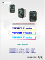
High-Performance Vector Control AC Drive
User Manual
TOPVERT G1 series
TOPVERT H1 series
TOPVERT P1 series
0.4kW
0.4kW
0.75kW
315kW
75kW
400kW
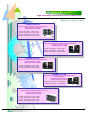
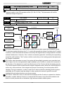
TOPVERT FAMILY>>
High performance Sensorless Vector Control drive
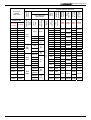
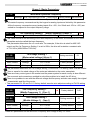
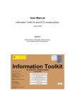
Members of Topvert family
TOPVERT E1 Series
High performance general purpose compact drive
Sensorless Vector Control
Output frequency:0.1-600Hz
1-Phase, 90~132VAC , 0.2kW~1.5kW
1-phase, 180~264VAC, 0.4kW~2.2kW
3-phase, 180~264VAC, 0.4kW~7.5kW
3-phase, 342~528VAC, 0.75kW~7.5kW
TOPVERT G1 series
High performance general purpose multi-function drive
Sensorless Vector Control,
output frequency:0.1-600Hz
1-phase, 180~264VAC, 0.4kW~2.2kW
3-phase, 180~264VAC, 0.4kW~75kW
3-phase, 342~528VAC, 0.75kW~315kW
TOPVERT H1 series
High performance multi-function high speed drive
Sensorless Vector Control
output frequency:0.1-6000Hz
1-phase, 180~264VAC, 0.4kW~2.2kW
3-phase, 180~264VAC, 0.4kW~75kW
3-phase, 342~528VAC, 0.75kW~75kW
TOPVERT P1 series
High performance multi-function variable torque drive
for Fan & Pump
Sensorless Vector Control
output frequency:0.1-600Hz
3-phase, 180~264VAC, 0.75kW~90kW
3-phase, 342~528VAC, 1.5kW~400kW
TOPVERT S1 series
High performance general purpose micro drive
Sensorless Vector Control
Output frequecy :0.1-600Hz
1-Phase, 90~132VAC , 0.2kW~0.75kW
1-phase, 180~264VAC, 0.4kW~2.2kW
3-phase, 180~264VAC, 0.4kW~3.7kW
3-phase, 342~528VAC, 0.4kW~3.7kW
TOPVERT G1/H1/P1 Series
PREFACE
Thank you for choosing TOPTEK’S TOPVERT G1, H1 and P1 Series Drive. TOPVERT G1, H1 and
P1 Series are Sensorless current vector control high-performance Drive. They were manufactured by
adopting high-quality components, material and incorporating the latest microprocessor technology
available.
This renewed user manual, besides revised the errors on previous 6328 edition.
We change the order of Chapter 5 and Chapter 6. The major different are the difference of Firmware
version update from 1.xx to 2.xx. The 2.xx version is more powerful, total parameter no. is over 500.
the main difference as below:
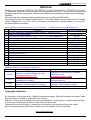
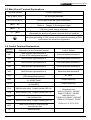
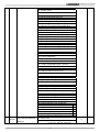
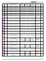
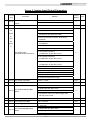
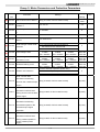
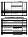
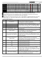
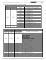
New functions of Firmware version 2.xx ( a symbol ‘◎’will be shown on its parameter no.)
Functions
Relative Parameters
1 Provide Parameters Read/Save/Copy function (Need a PU-02 )
2 Add on 575V class models
Pr0-00, Pr0-01
3 Parameter reset for 50/60Hz, 240V / 415V / 575V motor application
Pr0-02
4 Source of the Master Frequency Command from PG
Pr0-18
5 Parameter Team selection
Pr0-25
Pr1-24〜Pr1-35
6 Skip Frequency up to 6
Pr1-36〜Pr1-42
7 2nd V/F curve setting
8 FWD/REV terminals action by Level Trigger
Pr2-07
9 Delay time of Multi-Function Output terminals
Pr2-19
10 PLC Run Operation Mode after recover from power interruption
Pr4-33
Pr5-24〜Pr5-39
11 Fault Record up to 16
Pr5-40〜Pr5-46
12 Motor 2 parameters
Pr5-48〜Pr5-49
13 Motor selection between Y and ∆ as well as between 2 motors
14 Heatsink Over-Heat pre–warning setting (oH2)
Pr5-47
15 PG Type and direction setting for PID and frequency command
Pr9-01
16 PG Feedback compensation limit
Pr9-09
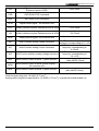
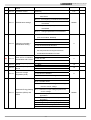
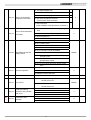
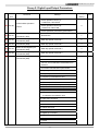
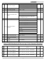
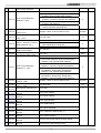
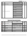
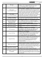
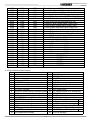
Modified functions on Firmware version 2.xx
Parameter
Firmware version 2.xx
Depress the PROG key and hold 3
second to complete Parameter reset
Pr0-02
(Firmware version ≧2.04)
Digital Input terminals status select—By
Pr2-10
Hexadecimal numbers
The PLC Run or MSS Run Operation
Pr4-32
Direction—By Hexadecimal numbers
Pr5-02
Slip Compensation of Motor set in RPM
Firmware version 1.xx
Depress the PROG key to complete
Parameter reset
(Firmware version ≦2.03)
Digital Input terminals status select—By
Decimal numbers
The PLC Run or MSS Run Operation
Direction—By Decimal numbers
Slip Compensation of Motor set in %
Copyright statement
All information in this manual are Toptek’s intellectual property. Even we had done our best to make
this manual but is unable to guarantee 100% correct.
Based on " Never Stop for better but perfect accomplished " quality policy, our product permanently
in the journey which perfectly strives for perfection to the pursue,
Therefore we reserve the right to change the information in this manual without prior notice.
But we will continue the latest edition document in our website, for free download.
http://www.toptek.biz
TOPVERT G1/H1/P1 Series
Getting Started
This manual will be helpful in the installation, parameter setting, troubleshooting, and daily
maintenance of the drives. To guarantee safe operation of the equipment, read the following safety
guidelines before connecting power to the Drives. Keep this operating manual handy and distribute to
all users for reference.
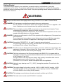
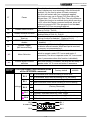
WARNING
Always read this manual thoroughly before using TOPVERT G1,H1 and P1 Series Drives.
DANGER! AC input power must be disconnected before any maintenance.
Do not connect or disconnect wires and connectors while power is applied to the
circuit. Maintenance must be performed by qualified technicians.
CAUTION! There are highly sensitive MOS components on the printed circuit boards. These
components are especially sensitive to static electricity.
To avoid damage to these components, do not touch these components or the circuit
boards with metal objects or your bare hands.
DANGER! A charge may still remain in the DC-link capacitor with voltages even if the power has
been turned off.
To avoid personal injury, please ensure that power has turned off before operating
Drive and wait ten minutes for capacitors to discharge to safe voltage levels.
CAUTION! Ground the TOPVERT G1, H1 and P1 using the ground terminal.
The grounding method must comply with the laws of the country where the Drive is to
be installed. Refer to Basic Wiring Diagram.
DANGER! The Drive may be destroyed beyond repair if incorrect cables are connected to the
input/output terminals. Never connect the Drive output terminals U/T1, V/T2, and
W/T3 directly to the AC main circuit power supply.
CAUTION! The final enclosures of the Drive must comply with EN50178. (Live parts shall be
arranged in enclosures or located behind barriers that meet at least the requirements
of the Protective Type IP20.
The top surface of the enclosures or barrier that is easily accessible shall meet at
least the requirements of the Protective Type IP40).
(TOPVERT G1, H1 and P1 Series corresponds with this regulation.)
CAUTION! Heat sink may heat up over 70℃ (158℉), during the operation. Do not touch the
heat sink.
CAUTION! The rated voltage for the drive must be ≤ 240V (≤ 480V for 460V models, ≤ 600V
For 575V models) and the mains supply current capacity must be ≤ 5000A RMS
(≤10000A RMS for the ≥ 40hp (30kW) models).
CAUTION! The leakage current between chassis and earth could be up to 22mA.
CAUTION! The load motor should meet IEC:60034-1 standard.
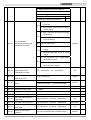
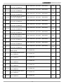
INDEX
CHAPTER 1 RECEIVING AND INSPECTION
1-1 Nameplate Information……………………………………………………………………..
1-2 Model Explanation….……………………………………………………………………....
1-3 Explanation of Production control data…………………………………………………..
1-1
1-1
1-1
CHAPTER 2 STORAGE AND INSTALLATION
2-1 Storage….………………………………………………………………………………........
2-2 Installation………………………………………………………………………………........
2-1
2-1
2-3 Installation Environment….………………………………………………………………… 2-2
2-4 Dimensions…..………………………………………………………………………………. 2-3
2-5 Embedded Installation………………………………………………………………........... 2-8
2-6 Digital Programming Keypad……………………………………………………….......... 2-10
CHAPTER 3 WIRING
3-1 Basic Wiring Diagram….............................................................................................. 3-1
3-2 Wiring Diagram of Optional Peripheral devices.......................................................... 3-2
3-3 Main Circuit Terminal Explanations........................................................................... 3-6
3-4 Control Terminal Explanations...................................................................................
3-6
3-5 Component Explanations………................................................................................ 3-8
3-6 Wiring Notice……….................................................................................................
3-12
CHAPTER 4 DIGITAL KEYPAD OPERATION
4-1 Description of the Digital Keypad...............................................................................
4-2 Explanations of Display Messages.............................................................................
4-3 Operation Steps….………………………….................................................................
4-1
4-2
4-2
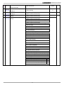
CHAPTER 5 FUNCTIONS AND PARAMETER SUMMARY..……….......................
CHAPTER 6 DESCRIPTION OF PARAMETER SETTINGS………………………...
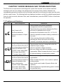
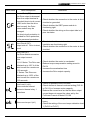
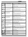
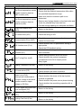
CHAPTER 7 ERROR MESSAGE AND TROUBLESHOOTING
5-1
6-1
7-1 Problems and Solutions.............................................................................................
7-1
7-2 Electromagnetic/Induction Noise..............................................................................
7-6
7-3 Environmental Condition............................................................................................
7-6
7-4 Affecting Other Machines............................................................................................. 7-7
CHAPTER 8 STANDARD SPECIFICATIONS .............................................................. 8-1
CHAPTER 9 DYNAMIC BRAKE AND BRAKING RESISTORS
9-1 The Braking function design of Topvert G1, H1 and P1 series…………....................... 9-1
9-2 Dynamic Braking unit (TDBU series)………………………………..…………................. 9-4
9-3 Braking Resistor (TDBR series)………………………………..…………........................ 9-5
CHAPTER 10 SPEED FEEDBACK PG CARD ….…………....................................... 10-1
TOPVERT G1/H1/P1 Series
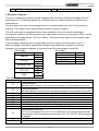
CHAPTER 1 RECEIVING AND INSPECTION
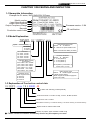
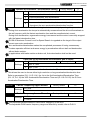
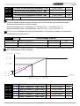
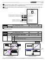
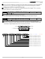
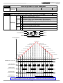
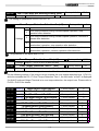
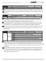
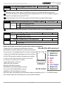
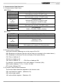
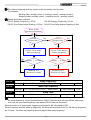
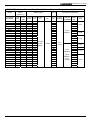
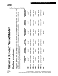
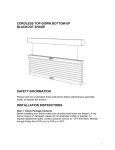
1-1 Nameplate Information
Example for G1 series, 3HP/2.2kW 230V 3-Phase
Model number
Input Specifications
Output Specifications
Output Frequency Range
Firmware version : 2.04
Barcode
Production control data
CE certification
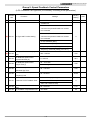
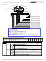
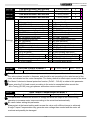
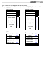
1-2 Model Explanation
TOPVERT G1 - 232P2x- xxxx
Extension/Interface cards
Blank or ‘N’: no selection
01 : TEK-PG-01 speed feedback card
Toptek AC drive Family
G1 series
H1 series
P1 series
(Refer to Accessories catalog for detail)
AC Power source
21= 230V 1 Phase
23= 230V 3 Phase
43= 460V 3 Phase
63= 575V 3 Phase
Enclosure Protection
Blank or ‘N’: Standard
0 : IP 00 ( NEMA 0)
1 : IP 20 ( NEMA 1)
2 : IP 21 ( NEMA 1)
Applicable Motor Capacity
(4 Pole Motor)
0P4= 0.4kW 0P7= 0.75kW
1P5= 1.5kW 2P2= 2.2kW
3P7= 3.7kW 5P5= 5.5kW
7P5= 7.5kW 011= 11kW
022= 22kW 075= 75kW
160= 160kW 315= 315kW
(IP 20 (NEMA 1) as standard in
Frame code A , B & C)
Brake chopper option
Blank or ‘N’: Brake chopper not include
D: Brake chopper built-in
(Brake chopper as standard equipped in
Frame code A & B)
Hardware version
Blank: original version
A: version A
B: version B
Z: version Z
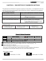
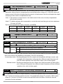
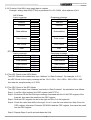
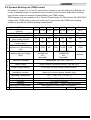
1-3 Explanation of Production control data
G1-232P2 - xxxx T 8 5 00001-08
Motor V/F selecting Preset (Pr0-02)
Production Month:1~9=Jan. to Sep., O=Oct., N=Nov.,D=Dec.
Production Year: 5=2005
Production Factory: T=Taiwan factory, F=Fuzhou factory, X=Ximan factory
Option Code or custom-made code
Model: G1 series, 230V 3 Phase 2.2kW / 3Hp
● Please contact the dealers immediately should any discrepancy occurred.
1-1
TOPVERT G1/H1/P1 Series
CHAPTER 2 STORAGE AND INSTALLATION
2-1 Storage
The Drive should be kept in the shipping carton before installation. In order to retain the warranty
coverage, the Drive should be stored properly when it is not to be used for an extended period of time.
Ambient Conditions:
Operation
Air Temperature: -10℃ to +40℃ (14℉ to 104℉)
Atmosphere pressure: 86 to 106 kPa
Installation Site Altitude: below 1000m
Vibration: Maximum 9.80 m/s2 (1G) at less than 20Hz
Maximum 5.88 m/s2 (0.6G) at 20Hz to 50Hz
Storage
Temperature: -20℃ to +60℃ (-4℉ to 149℉)
Relative Humidity: Less than 90%, no condensation allowed
Atmosphere pressure: 86 to 106 kPa
Transportation Temperature: -20℃ to +60℃ (-4℉to 140℉)
Relative Humidity: Less than 90%, no condensation allowed
Atmosphere pressure: 86 to 106 kPa
Vibration: Maximum 9.80 m/s2 (1G) at less than 20Hz, Maximum 5.88m/s2 (0.6G) at
20Hz to 50Hz
Pollution Degree 2: good for a factory type environment.
2-2 Installation
CAUTION
The control, power supply and motor leads must be laid separately. They must not be
fed through the same cable conduit / trenching.
High voltage insulation test equipment must not be used on cables connected to the
drive.
Improper installation of the Drive will greatly reduce its life. Be sure to observe the following
precautions when selecting a mounting location.
Failure to observe these precautions may void the warranty!
2-1
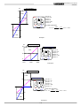
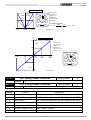
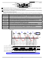
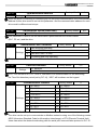
TOPVERT G1/H1/P1 Series
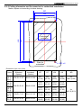
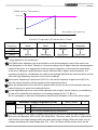
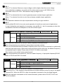
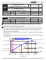
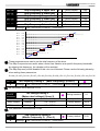
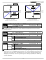
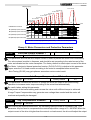
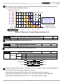
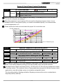
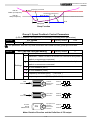
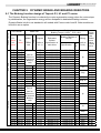
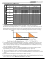
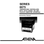
The Drive generates heat. Allow sufficient space around the unit for heat dissipation.
Mount the Drive vertically and do not restrict the air flow to the heat sink fins.
H
W
W
Air Flow
H
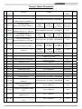
Frame Code
A
B
C
D
E
F
G
W (min)
mm(inch)
50 (2)
75 (3)
75 (3)
100 (4)
150 (6)
200 (8)
400 (16)
H (min)
mm(inch)
150 (6)
175 (7)
200 (8)
300 (12)
450 (18)
650 (26)
850 (33)
Air flow
CMH (m3/hr)
110
160
350
650
900
1350
1800
2-3 Installation Environments
▲ Do not install the Drive in a place subjected to high humidity, steam, dust areas.
▲ Do not install the Drive in a place subjected to corrosive gases or liquids.
▲ Do not install the Drive in a place subjected to airborne dust or metallic particles.
▲ Do not install the Drive in a place subjected to excessive vibration.
▲ Do not mount the Drive near heat-radiating elements
▲ Do not install the Drive in a place subjected to temperature exceed : -10℃ to +40℃
(14℉ to 104℉)
2-2
TOPVERT G1/H1/P1 Series
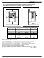
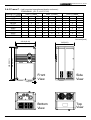
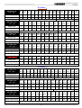
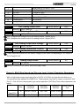
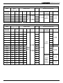
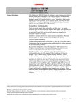
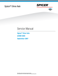
2-4 Dimensions
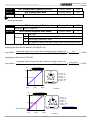
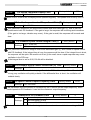
2-4-1 Frame A --(wall-mounted strengthened plastic enclosure):
IP20/NEMA 1
(G1-A, H1-A, P1-A)
Capacity
Power 230V 1 phase 230V 3 Phase
kW/Hp
G1
H1
G1 H1
P1
0.4/0.5
V
V
V
V
0.75/1
V
V
V
V
V
1.5/2
V
V
V
V
V
2.2/3
V
V
V
V
V
3.7/5
V
V
V
5.5/7.5
V
V
V
7.5/10
V
11/15
160.0(6.30)
V
V
V
V
V
V
V
V
V
V
V
V
V
V
V
V
V
V
186(7.32)
575V 3 Phase
G1
H1
P1
V
V
V
V
V
V
V
V
V
V
V
V
V
V
V
V
V
V
Unit:mm(inch)
230.0(9.06)
140.0(5.51)
250.0(9.84)
460V 3 Phase
G1
H1
P1
Front
View
Side
View
Bottom
View
Top
View
6.0(0.24)
2-3
TOPVERT G1/H1/P1 Series
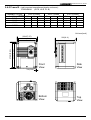
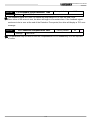
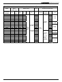
2-4-2 Frame B --(wall-mounted strengthened plastic enclosure):
IP20/NEMA 1
Capacity
Power
kW/Hp
7.5/10
11/15
15/20
18.5/25
(G1-B, H1-B, P1-B)
230V 3 Phase
G1
H1
P1
V
V
V
460V 3 Phase
G1
H1
P1
V
V
V
V
V
V
575V 3 Phase
G1
H1
P1
V
V
V
V
V
V
Unit:mm(inch)
206(8.11)
255.0(10.04)
275.0(10.83)
200.0(7.87)
180.0(7.09)
Front
View
Side
View
Bottom
View
Top
View
6.0(0.24)
2-4
TOPVERT G1/H1/P1 Series
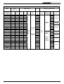
2-4-3 Frame C --(wall-mounted strengthened plastic enclosure):
IP20/NEMA 1, (G1-C, H1-C, P1-C)
Capacity
Power
kW/Hp
11/15
15/20
18.5/25
22/30
30/40
37/50
45/60
55/75
230V 3 Phase
G1
V
V
V
V
H1
V
V
V
V
460V 3 Phase
P1
V
V
V
V
G1
H1
V
V
V
V
V
V
V
V
V
V
575V 3 Phase
P1
V
V
V
V
V
G1
H1
V
V
V
V
V
V
V
V
V
V
P1
V
V
V
V
V
Unit:mm(inch)
260.0(10.24)
245(9.65)
440.0(17.32)
460.0(18.11)
236.0(9.29)
Front
View
Side
View
Bottom
View
Top
View
9.0(0.35)
2-5
TOPVERT G1/H1/P1 Series
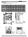
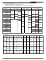
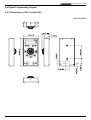
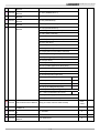
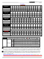
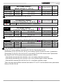
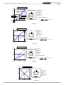
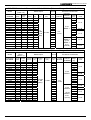
2-4-4 Frame D, E, F & G --( wall-mounted galvanized steel with baking varnish shell):
IP00/NEMA 0, (IP20/IP21 NEMA 1 optional)
(G1-D, H1-D, P1-D, G1-E, H1-E, P1-E, G1-F, H1-F, P1-F, G1-G, P1-G)
Power
230V 3 Phase
Capacity
kW/Hp
G1
H1
P1
30/40
37/50
G1-D H1-D
45/60
P1-D
55/75
H1-F
G1-F
75/100
P1-F
90/125
G1-G
110/150
P1-G
132/175
160/215
185/250
220/300
280/375
315/422
400/535
450/600
500/670
560/750
630/850
460V 3 Phase
G1
H1
G1-D
H1-D
575V 3 Phase
P1
P1-D
G1-E
G1
H1
P1
G1-D
H1-D
P1-D
G1-E
P1-E
P1-E
G1-F
G1-F
P1-F
G1-G
P1-F
G1-G
P1-G
P1-G
Unit: mm (inch)
Frame
W
H
D
W1
W2
W3
H1
H2
D1
D2
Φ1
386.0
617.0
298.3
230.0
376.0
13.0
591.5
566.5
290.5
131.5
13
(11.74)
(9.06)
(14.80)
(0.51)
(23.29)
(22.30)
(11.44)
(5.18)
(0.51)
324.3
230.0
376.0
13.0
657.5
632.5
316.5
157.5
13
(12.77)
(9.06)
(14.80)
(0.51)
(25.89)
(24.90)
(12.46)
(6.20)
(0.51)
G1-D
H1-D
(15.20) (24.29)
P1-D
G1-E
386.0
683.0
H1-E
(15.20) (26.89)
P1-E
G1-F
496.0
810.0
352.1
260.0
484.0
13.0
784.0
764.0
344.0
180.5
13
H1-F
(19.53)
(31.89)
(13.86)
(10.24)
(19.06)
(0.51)
(30.87)
(30.08)
(13.54)
(7.11)
(0.51)
P1-F
G1-G
732
1196
413
410
720.0
13.0
1156
1133
404.9
177.30
13
P1-G
(28.82)
(47.09)
(16.26)
(16.14)
(28.35)
(0.51)
(45.51)
(44.61)
(15.94)
(6.98)
(0.51)
2-6
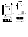
TOPVERT G1/H1/P1 Series
W
D
D1
Ø1
H2
H
H1
W1
F ro n t
V ie w
S id e
V ie w
B o tto m
V ie w
Top
V ie w
D2
W3
W2
2-7
TOPVERT G1/H1/P1 Series
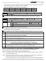
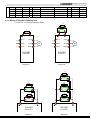
2-5 Embedded Installation (To isolate the ventilation system from panel)
Embedded Installation can isolate the ventilation system from panel, the hot air was isolated thus the
smaller size or totally enclosed panel can be used. It is easy to accomplish by make a square cutting
and install 2 kickstands.(refer to 2-5-1 ~ 2-5-3 ).
In Topvert G1, H1 and P1 series, all drive with frame code C and above were designed can be
embedded Installation.
2-5-1 Frame C:
Upper side kickstand (Option)
M8*20 screw *4
Plate for
embedded
M8*12 screw *4
Lower side kickstand (Option)
2-5-2 Frame D, E, F & G :
U p p e r s id e k ic k s ta n d ( O p tio n )
P la te fo r
em bedded
M 8 *1 2 s c re w *4
L o w e r s id e k ic k s ta n d (O p tio n )
2-8
TOPVERT G1/H1/P1 Series
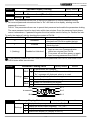
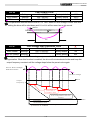
2-5-3 Cutting dimension and Accessories for embedded installation
Make a square cut according to below drawing.
W7
W8
H7
H8
Cutting area for
embedded
installation
Plate for
embedded
Dimension Unit: mm (inch)
Upper side
Frame
kickstand
(Option)
G1-C
H1-C
EN-G1-C-22
P1-C
G1-D
H1-D
P1-D
EN-G1-D-33
G1-E
H1-E
P1-E
G1-F
H1-F
EN-G1-F-33
P1-F
G1-G
EN-G1-G-34
P1-G
ØD x 4
Lower side
kickstand
(Option)
W7
H7
W8
H8
ΦD
EN-G1-C-22
257
(10.19)
462
(18.19)
236
(9.29)
490
(19.29)
4x
Φ9.0 (0.35)
379.0
593.2
(14.91) (23.35)
230.0
(9.05)
621.2
(24.44)
379.0
659.7
(14.91) (26.18)
230.0
(9.05)
687.7
(27.05)
EN-G1-F-32
487.0
(19.16)
789.2
(31.07)
260.0
(10.23)
817.2
(32.15)
EN-G1-G-33
722.0
(28.43)
1166
(45.90)
410
(16.14)
1194
(25.40)
EN-G1-D-32
2-9
4x
Φ13.0 (0.51)
TOPVERT G1/H1/P1 Series
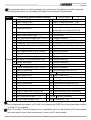
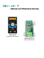
2-6 Digital Programming Keypad
2-6-1 Dimensions of PU-01 and PU-02
Unit:mm(inch)
2-10
TOPVERT G1/H1/P1 Series
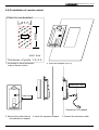
2-6-2 Installation of remote control
P late for em bedded
138.6
67.7
C ut
U nit: m m
T hickness of plate :1.2~2.0
1. According to above dimension,
make a square cutting.
2. Insert the adapter (PR-01)
Extension Cable
Cable Hole
Connect to CPU board
3. Remove the cable hole on 4. Insert the keypad to adapter.
the backside of adapter.
2-11
5. Connect the extension cable
TOPVERT G1/H1/P1 Series
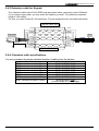
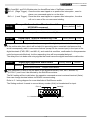
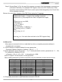
2-6-3 Extension cable for Keypad:
The extension cable is the RJ-45 8P8C twist-pair shield cable, commonly used in Ethernet.
If you need a longer cable, you may make the cable by yourself. The maximum extension
length is 150 meters.
For this, you need 2 extra RJ-45 connectors. The pin assignment two connectors as below:
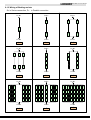
Extension cable wiring
1 Or/Wh
1 Or/Wh
2 Orange
2 Orange
3 Gr/Wh
3 Gr/Wh
4 Blue
4 Blue
5 Bl/Wh
5 Bl/Wh
6 Green
6 Green
7 Br/Wh
7 Br/Wh
8 Brown
8 Brown
From Inverter
To PU
1
8
SHIELD
( Gray )
1
Single side grounding only
2-6-4: Extension cable specifications
You may purchase the below standard lengths of cables from the dealers.
Specification
8P8C, twisted and shield, 1M
8P8C, twisted and shield, 2M
8P8C, twisted and shield, 3M
8P8C, twisted and shield, 5M
8P8C, twisted and shield, 10M
8P8C, twisted and shield, 15M
8P8C, twisted and shield, 20M
Ordering Number
TMCA-RC8P8C-001S
TMCA-RC8P8C-002S
TMCA-RC8P8C-003S
TMCA-RC8P8C-005S
TMCA-RC8P8C-010S
TMCA-RC8P8C-015S
TMCA-RC8P8C-020S
TMCA-RC8P8C-XXXS
(Contact dealer for other length)
8P8C, twisted and shield, XXXM
2-12
( Blue )
8
TOPVERT G1/H1/P1Series
CHAPTER 3 WIRING
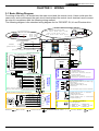
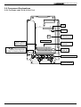
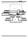
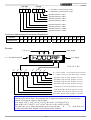
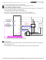
3-1 Basic Wiring Diagram
For wiring of the drive, it is divided into the main circuit and the control circuit. Users could open the
case cover, and could inspect the main circuit terminal and the control circuit terminal; users connect
the circuit in compliance with the following wiring method.
The following diagram is the standard wiring diagram for the TOPVERT G1,H1 and P1series drive.
D C C h o k e (O p tio n )
直流電抗器
配 ) F ra m e c o d e :
M o d e ls (選
w ith
G 1 -C , G 1 -D , G 1 -E , G 1 -F , G 1 -G ,
H 1 -C , H 1 -D , H 1 -E , H 1 -F ,
P 1 -C , P 1 -D , P 1 -E , P 1 -F , P 1 -G
M o d e ls w ith F ra m e c o d e :
G 1 -A , G 1 -B ,
B ra k in g R e s is to r
TDBR
H 1 -A , H 1 -B ,
P 1 -A , P 1 -B
+ B1
B2
(O p tio n )
+ B1
P1
M .C .
S (L 2 )
U (T 1 )
M o to r
T (L 3 )
V (T 2 )
M
3~
Factory Default
Use external power source
+
-
FW D
REV / STO P
REV
(M u lti-S te p 2 )
M I2
(M u lti-S te p 3 )
M I3
(M u lti-S te p 4 )
M I4
(R e s e t)
M I5
(R e s e t)
24V
FW D
M I4
M I5
(D I)
REV
M I1
M I2
M I3
M I6
DCM
(D O )
E
M u lti-fu n c tio n A n a lo g s ig n a l c o m m a n d
+12V 20m A
REV
0
1
FW D
3
Hz
60
+12V
1
(F re q u e n c y C o m m a n d )
0 〜 1 0 V (2 0 K Ω )
4 〜 2 0 m A (2 5 0 Ω )
2
-1 0 〜 + 1 0 V (1 0 K Ω )
+12V
AVI
ACI
AUI
ACM
-1 2 V 2 0 m A
-1 2 V
(A I)
V R : 5〜 10 K Ω
R e m a rk : ◎ → M a in c irc u it
○ → C o n tro l c irc u it
→ S h ie ld e d le a d s & C a b le
3-1
GND
E
R 1A
R1B
C o n ta c t o u tp u t 1
(in d ic a te s m a lfu n c tio n )
R1C
2 4 0 V A C /2 .5 A , 1 2 0 V A C /5 A , 2 4 V D C /5 A
R2A
C o n ta c t o u tp u t 2
(in d ic a te s d riv e ru n n in g )
R 2C
MO1
2 4 0 V A C /2 .5 A , 1 2 0 V A C /5 A , 2 4 V D C /5 A
O p e n c o lle c to r o u tp u t 1
(p re -s e t s p e e d a tta in e d 1 (fo rw a rd o n ly ))
4 8 V D C /5 0 m A
O p e n c o lle c to r o u tp u t 2
(in d ic a te s d riv e re a d y fo r u s e )
MO2
4 8 V D C /5 0 m A
MCM
ACO
ACM
AVO
(A O )
Serial port
60
-1 2 V
2
Multi-function
Analog input
3
PG
+12V
VP
DCM
(R y )
Multi-function
Analog output
(E .F .)
D ig ita l S ig n a l C o m m o n
* D o n ´t a p p ly a n y v o lta g e
d ire c tly to th o s e te rm in a ls
SW 1
Multi-function
Digital output
(M u lti-S te p 4 )
B
Multi-function
Relay output
(M u lti-S te p 2 )
(M u lti-S te p 3 )
B
O C 12V
F a c to ry D e fa u lt
Multi-function
Digital input
Factory Default
REV / STOP
(M u lti-S te p 1 )
(O p tio n )
TP 5V
DCM
FW D / STOP
A
A
B
SW 2
M I6
C o n tro l s ig n a l in p u t
S in k M o d e
A
S p e e d fe e d b a c k
P G c a rd
E
SW 1
(S in k )
M a in c irc u it
C o n tro l c irc u it
M I1
S o u rc e M o d e
S o u rc e
TOPVERT G1
TOPVERT H1
TOPVERT P1
24V
FW D / STOP
(E .F .)
R e fe re n c e o f e x te rn a l p o w e r
-
W (T 3 )
C o n tro l s ig n a l in p u t
24V
B2
-
B2
[ U s e R (L 1 ), S (L 2 ) fo r 1 -p h a s e m o d e ls ]
(M u lti-S te p 1 )
+ B1
R (L 1 )
3 -P h a s e
p o w e r s o u rc e
U s e in te rn a l p o w e r s o u rc e
P1
TDBR
** B 2 te rm in a l is O p tio n a l
N o n e F u s e B re a k e r
NFB
Jum per
TD
BR
TDBU
87654321
(
P h o to -c o u p le r o u tp u t c o m m o n te rm in a l
A n a lo g c u rre n t o u tp u t -- 4 〜 2 0 m A D C
(o u tp u t fre q u e n c y )
A n a lo g S ig n a l C o m m o n
A n a lo g v o lta g e o u tp u t -- 0 〜 1 0 V D C /2 m A
(o u tp u t fre q u e n c y)
R S -4 8 5 (M O D B U S )
P in a s s ig n m e n t :
1 : R e s e rv e d
2 : R e s e rv e d
3: G ND
4: SG - 5: SG + 6: +5V
7 : R e s e rv e d
8 : R e s e rv e d
) → F a c to ry d e fa u lt
→ o p tio n
TOPVERT G1/H1/P1Series
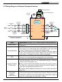
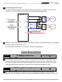
3-2 Wiring Diagram of Optional Peripheral devices
TDBR
B1
B1
B2
TOPVERT G1
TOPVERT H1
TOPVERT P1
Input AC
Reactor
Input EMI Filter
Power
Source
Dynamic Braking Unit
TDBR
P1
Magnetic
contactor
B2
TDBU
DC-Link
Choke
Fuse/NFB
Braking Resistor
Output AC
Reactor
R(L1)
U(T1)
S(L2)
V(T2)
T(L3)
W(T3)
M
3~
Motor
Zero-phase
Reactor
Zero-phase
Reactor
Please grounded following
electrician regulations
Items
Power source
Fuse/NFB/ELCB
Magnetic contactor
(MC)
Input AC Reactor
(TIAR-xxxxx)
Zero-phase
Reactor
(TZAR-xxxxx)
Explanations (Refer to 3-2-1 to select proper Peripheral devices)
Please follow the specific power supply requirements shown in
Chapter 8
There might be an inrush current during power up. Please check
the chart of 3-2-1and select the correct NFB or fuse with rated
current. Please do not use NFB as a Run/Stop switch
If the electric-leakage circuit breaker is installed in the drive, please
select the sensing current above 200ma with the action time of
more than 0.1 second to have these actions accessible.
Please do not use a Magnetic contactor as the Run/Stop switch of
the drive, as it will reduce the operating life cycle of the drive.
Used to improve the input power factor, to reduce harmonics and
provide protection from AC line disturbances.(surges, switching
spikes, short interruptions, etc.).
AC line reactor should be installed when the power supply capacity
is 500kVA or more and exceeds 6 times the inverter capacity, or
the mains wiring distance less than 10m.
To reduce electromagnetic interference or noise on the input side of
the drive.
Zero phase reactors are used to reduce radio noise especially
when audio equipment is installed near the drive. Effective for noise
reduction on both the input and output sides. Attenuation quality is
good for a wide range from AM band to 10MHz.
3-2
TOPVERT G1/H1/P1Series
All electrical equipment, including AC motor drives, will generate
high-frequency/low-frequency noise and will interfere with
peripheral equipment by radiation or conduction when in operation.
By using an EMI filter with correct installation, most of the
interference can be eliminated.
Input EMI filter
(TIRF-xxxxx)
DC-Link Choke
(TDLC-xxxx)
(Frame C and
above only)
Dynamic Braking
Unit (TDBU-xxxx)
Braking Resistor
(TDBR-xxxxx)
Output AC Reactor
(TOAR-xxxxx)
Motor
To reducing the ripple current, reducing harmonics and increasing
the power factor.
To protect the smoothing capacitor
Used to reduce the deceleration time of the motor when drive’s
Braking Chopper is not built-in.
To absorb the motor regeneration energy when the motor stops by
deceleration.
To reduce dv/dt and motor terminal peak voltage in long motor lead
applications.
For applications with long motor cable 20 to 250 meter, it is
necessary to install a reactor at the inverter output side.
Please select proper motor according to chapter 8
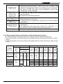
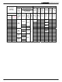
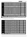
3-2-1 Wiring specifications and Selection of Optional Peripheral devices
1.In order to keep the voltage drop within 2%, please follow the specified cable size
2. For 1-phase drives, the current rating of the breaker shall be 2 times maximum input current
rating.
3. For 3-phase drives, the current rating of the breaker shall be 2 times maximum output current
rating.
Wiring specifications
Input AC
Reactor
Input EMI
filter
DC-Link
Choke
Output
AC
Reactor
3.5(12)
2(14)
Capacity
(A)
212P2
2(14)
Magnetic
contactor
(MC)
211P5
M4
(M4)
0.75 (18)
210P7
Control
circuit
Grounding
circuit
210P4
Capacity
(A)
HIV cable mm/
(AWG/MCM)
NFB
ELCB
Wire type and size
Main
circuit
G1-xxxxx
H1-xxxxx
(Grounding
circuit)
Main circuit
Series/model
Terminal
screws
AC source:
1 phase
230V class
Optional Peripheral devices
TIARxxxxx
TIRFxxxxx
TDLCxxxxx
TOARxxxxx
15
10
21005
21015
210P4
23003
20
15
21010
21020
210P7
23005
30
20
21015
21030
211P5
23010
50
30
21020
21040
212P2
23015
3-3
TOPVERT G1/H1/P1Series
Wiring specifications
23003
23005
23010
23015
23020
23030
23040
23060
23080
23090
23120
23160
23200
23240
23280
23360
23500
2(14)
M4
(M4)
3.5(12)
5.5(10) 3.5(12)
M12
(M5)
22(4)
38(2)
14
(6)
60(1/0)
80(3/0)
100(4/0)
M16
(M8)
5.5(10)
0.75 (18)
14(6)
M6
(M4)
2(14)
38(2)
125(250)
150(300)
3-4
15
30
40
50
60
100
125
150
175
125
300
350
400
500
800
Output
AC
Reactor
Input AC
Reactor
Capacity
(A)
5
10
15
20
30
50
75
100
125
150
175
200
250
300
350
400
500
10
DC-Link
Choke
Magnetic
contactor
(MC)
Capacity
(A)
TIARxxxxx
Input
EMI
filter
NFB
ELCB
Control
circuit
230P7
231P5
232P2
233P7
235P5
237P5
23011
23015
23018
23022
23030
23037
23045
23055
23075
23090
23110
HIV cable mm/
(AWG/MCM)
Grounding
circuit
230P4
230P7
231P5
232P2
233P7
235P5
237P5
23011
23015
23018
23022
23030
23037
23045
23055
23075
23090
Wire type and size
Main
circuit
G1-xxxxx
P1-xxxxx
H1-xxxxx
Main
Circuit
(Grounding
circuit)
Series/model
Terminal
screws
AC source:
3 phase
230V class
Optional Peripheral devices
TIRF- TDLC- TOARxxxxx xxxxx xxxxx
23005
23015
23030
23040
23060
23080
23090
23120
23160
23200
23240
23280
23360
23500
230P4
230P7
231P5
232P2
233P7
235P5
237P5
23011
23015
23018
23022
23030
23037
23045
23055
23075
23090
23003
23005
23010
23015
23020
23030
23040
23060
23080
23090
23120
23160
23200
23240
23280
23360
23500
TOPVERT G1/H1/P1Series
Wiring specifications
M16
(M8)
60(3/0)
80(3/0)
100(4/0)
125(250)
150(300)
2X100
(2X4/0)
2X125
(2X250)
2X150
(2X300)
2X200
(2X400)
TIRF- TDLC- TOARxxxxx xxxxx xxxxx
5
10
15
20
30
40
50
60
75
100
125
150
175
250
5
10
15
20
30
40
50
60
75
100
125
125
150
200
220
250
350
400
450
550
300
400
500
38
(1)
600
60
(3/0)
800
650
1000
800
43005 43005
43007
43010
43015
43020
43030
43040
43050
43060
43080
43090
43120
43150
43010
43020
43030
43040
43050
43065
43080
43100
43150
43200 43200
430P7
431P5
432P2
433P7
435P5
437P5
43011
43015
43018
43022
43030
43037
43045
43055
43075
43090
43110
43132
43160
43185
43250
43250
43290
43330 43300
43400
43400
43490
43220
3-5
1200
900
1500
1000
43005
43007
43010
43015
43020
43030
43040
43050
43060
43080
43090
43120
43150
43200
43250
43290
43330
43400
43490
43280
43660 43600
100
(4/0)
Output AC
Reactor
M12
(M5)
TIARxxxxx
DC-Link
Choke
43450
60(1/0)
22
(4)
Input EMI
filter
43400
38(1)
Input AC
Reactor
43400
22(4)
Capacity
(A)
43315
M6
(M4)
14
(6)
Magnetic
contactor
(MC)
43315
14(6)
Capacity
(A)
43280
2(12) 3.5(14)
3.5(12) 3.5(12)
5.5(10)
8
(8)
8(8)
NFB
ELCB
43280
M4
(M4)
2(14)
0.75 (18)
43220
2(14)
Control
circuit
431P5
432P2
433P7
435P5
437P5
43011
43015
43018
43022
43030
43037
43045
43055
43075
43090
43110
43132
43160
43185
43220
HIV cable mm/
(AWG/MCM)
Grounding
circuit
430P7
431P5
432P2
433P7
435P5
437P5
43011
43015
43018
43022
43030
43037
43045
43055
43075
43090
43110
43132
43160
43185
Wire type and size
Main
circuit
G1-xxxxx
P1-xxxxx
H1-xxxxx
Main
Circuit
(Grounding
circuit)
Series/model
Terminal
screws
AC source:
3 phase
460V class
Optional Peripheral devices
43660
43315
43800 43800 43400 43800
TOPVERT G1/H1/P1Series
3-3 Main Circuit Terminal Explanations
Terminal Symbol
Content Explanation
R(L1),S(L2),T(L3)
AC line input terminals
U(T1),V(T2),W(T3)
Drive output terminals motor connections
⊕/B1, B2
⊕/B1,
Θ
P1, ⊕/B1
Connections for Braking Resistor (optional)
Refer to Chapter 9 ( the selection chart)
Connecting terminals of the external Dynamic Brake Unit.
(DC Bus, power source terminals)
Connections for Power-improved DC Link Reactor (optional) .
Disconnect the short-circuit piece when the device is installed
Ground terminals, please have these terminals grounded following the
third-type grounding of 230V series and the special grounding of 460V
series within the electrician regulations
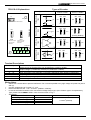
3-4 Control Terminal Explanations
Terminal
Symbols
Explanation on the Terminal Function
Factory Default
MI1
Multi-function input selection 1
(3-wire STOP-designated terminal)
multi-step speed command 1
MI2
Multi-function input selection 2
multi-step speed command 2
MI3
Multi-function input selection 3
multi-step speed command 3
MI4
Multi-function input selection 4
multi-step speed command 4
MI5
Multi-function input selection 5
Abnormal reset command
MI6
AVO
ACO
Multi-function input selection 6
(TRG-designated terminal)
Multi-function analog voltage output
(0~10VDC, 2mA)
Multi-function analog current output
(4~20mADC)
R1A
Multi-function relay 1 output contact (NO / a)
R1B
Multi-function relay 1 output contact (NC / b)
R1C
Multi-function relay 1 output contact
– the common end
R2A
Multi-function relay 2 output contact (NO / a)
R2C
Multi-function relay 2 output contact
– the common end
E
Shield terminal
3-6
EF input
Output frequency
Output frequency
Resistive Load
5A(N.O.)/3A(N.C.) 240VAC
5A(N.O.)/3A(N.C.) 24VDC
Inductive Load
1.5A(N.O.)/0.5A(N.C.) 240VAC
1.5A(N.O.)/0.5A(N.C.) 24VDC
Refer to Pr.2-19, Pr.2-20
TOPVERT G1/H1/P1Series
24V
Digital control source signal
Reference point is DCM
FWD
FWD RUN-STOP command
REV
REV RUN-STOP command
DCM
Digital control signal - the common end
+12V
Auxiliary reference power Reference point is ACM
+12V 20mA
-12V
Auxiliary reference power Reference point is ACM
-12V 20mA
ACM
Analog control signal - the common end
AVI
ACI
AUI
MO1
+24V 50mA
The maximum operation
frequency corresponding to 0~+10V
The maximum operation
Multi-Function analog current command
frequency corresponding to
4~20mA
The maximum operation
Multi-Function auxiliary analog voltage command
frequency corresponding to
-10~+10V
pre-set speed attained
Multi-function output terminal 1 (photo coupler)
(Max 48VDC 50mA)
Multi-Function analog voltage command
MCM
Multi-function output terminal (photo coupler) –
the common end
MO2
Multi-function output terminal 2 (photo coupler)
drive ready for use
(Max 48VDC 50mA)
Control signal wiring size: 18 AWG (0.75 mm2)
Analog control signal wire specification: 18 AWG (0.75 mm2), covered with shield twisted net.
3-7
TOPVERT G1/H1/P1Series
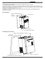
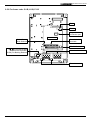
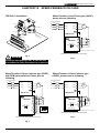
3-5 Component Explanations
3-5-1 For frame code: G1-A, H1-A, P1-A
Fault
Fault
Power
Power
Keypad
connection port
Control board
Sink / Source
Mode Selector
(
, ) For external DBU
And DC Bus terminals,
(B1,B2) For Braking Resistor
Control circuit
terminals
RS-485
Serial port
SW1
Main circuit terminals
Ground terminal
3-8
TOPVERT G1/H1/P1Series
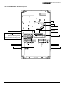
3-5-2 For frame code: G1-B, H1-B, P1-B
Fault
Fault
Power
Power
Keypad
connection port
Control board
Control circuit
terminals
Sink / Source
Mode Selector
RS-485 Serial port
SW1
(
, ) For external DBU
And DC Bus terminals,
(B1,B2) For Braking Resistor
Main circuit terminals
Ground terminal
3-9
TOPVERT G1/H1/P1Series
3-5-3 For frame code: G1-C, H1-B, P1-C
Fault
Fault
Power
Power
Keypad
connection port
Control board
Sink / Source Mode Selector
, ) For external DBU
And DC Bus terminals,
(B1,B2) For Braking Resistor
( P1) Connections for Power-improved
DC Link Reactor (optional)
Control circuit
terminals
(
SW1
RS-485 Serial port
Ground terminal
Main circuit terminals
Ground terminal
Main circuit terminals
3-10
TOPVERT G1/H1/P1Series
3-5-4 For frame code: G1-D, H1-D, P1-D, G1-E, H1-E, P1-E, G1-F, H1-F, P1-F,G1-G,P1-G
Control circuit terminals
Fault
Fault
Power
Power
Keypad
connection port
Sink / Source Mode Selector
(
, ) For external DBU
And DC Bus terminals,
(B1,B2) For Braking Resistor
( P1) Connections for Power-improved
DC Link Reactor (optional)
SW1
RS-485
Serial port
Ground terminal
Ground terminal
Main circuit terminals
Main circuit terminals
3-11
TOPVERT G1/H1/P1Series
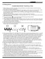
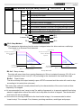
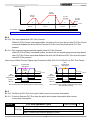
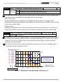
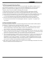
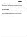
3-6 Wiring Notice:
PLEASE READ PRIOR TO INSTALLATION.
1. When wiring up, and that the wiring route specifications are settled, please conduct the wiring
following the electrician regulations.
2. The connection between the three-phase AC input power and the main circuit terminal R/L1, S/L2,
T/L3 has to set up a none-fusing switch in between. The best is to series connect with an
electro-magnetic contactor (MC) so as to cut off the power supply at the same time when the drive
protection function acts.
(The two ends of the electro-magnetic contactor should have the R-C Varistor).
3. There is no phase-order differentiation in the input power R/L1, S/L2, T/L3 and users could connect
with either one of use.
4. The ground terminal
is grounded with the third-type grounding method
(with the grounding impedance under 100Ω).
5. The grounding wire of the drive could not be grounded at the same time with machinery with grand
current loading, like that of the electric soldering machine and of the motor with grand horsepower;
they have to be grounded individually.
6. The shorter the ground wire, the better it is.
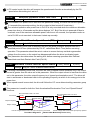
7. When several drives are grounded at the same time, be sure not to make it into a ground circuit.
Please refer to the following diagram:
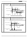
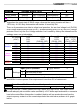
FWD
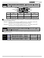
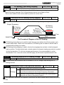
8. If the output terminals U/T1, V/T2 and W/T3 of the drive are connecting relatively to the U, V, and W
terminals of the motor, the FWD indicator located on the digital control panel of the drive will be lit,
and that means the drive is running forward, and the rotation direction of the motor will be shown as
the right hand side diagram above; if the REV indicator is lit, it means that the drive is running in
reverse direction, and the rotation direction will be of the opposite direction compared with the
above diagram. If users are not sure of whether the connection between output terminals
U/T1, V/T2 and W/T3 of the drive is of one-to-one connection with U, V, and W terminals of the
motor, simply swap either two wires among the U,V, and W terminals of the motor for correction if
the drive is running forward while the motor is running at reverse direction.
9. Ensuring the power voltage and the maximum current possible supplied.
10. When the “Digital Programming Unit” is displayed, please do not disconnect or dissemble any
wiring.
11. No braking resistor is installed within the TOPVERT G1, H1 and P1 series drive (option item),
therefore, be sure to purchase and install the braking resistor if to be used on occasions when the
loading inertia is great or that it is of frequent start/stop.
12. Be sure not to connect the AC power with the terminals U/T1, V/T2 and W/T3 of the drive.
13. Please tightly fasten the screws of the main circuit terminals so as to prevent sparks generated
due to the vibration and loosening of the screws.
14. Wiring of the main circuit and of the control circuit should be separated so as to prevent erroneous
actions. If the interlock connection is needed, please make it an intersection of 90°.
15. If terminals U/T1, V/T2 and W/T3 on the output side of the drive is in need of the noise wave-filter,
it is then necessary to use the induction-type L-Varistor, but be sure not to add in the
phase-carrying capacitor or the L-C- and R-C-type wave filters.
16. Please use the separating wire as much as possible during control wiring, and be sure not to
3-12
TOPVERT G1/H1/P1Series
expose the peeled-off separation net in front of the terminal to the external.
17. Please use the separating wire or tube as much as possible during power wiring, and ground these
two ends of the separating layer or tube to the Ground.
18. If the installation site of the drive is sensitive to interferences, please have the RFI filters installed,
and the closer the drive to the installation site, the better. In addition, the lower the carrier
frequency is, the less the interferences will be.
19. If the electric-leakage circuit breaker is installed in the drive, it could serve as the protection for the
electric-leakage error, and as the prevention on the erroneous actions of the electric-leakage
circuit breaker; please select the sensor current above 200ma with the action time of more than
0.1 second to have these actions accessible.
3-13
TOPVERT G1H1P1 Series
CHAPTER 4 DIGITAL KEYPAD OPERATION
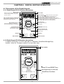
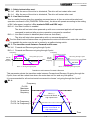
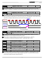
4-1 Description of the Digital Keypad
4-1-1 Digital Keypad PU-01 function descriptions
Main Display
PU-01
Display the drive status such as frequency,
current, voltage, parameter setting value
and alarm contents.
Part number
Status Display…… Display the drive's current status
360° Encoder style Fly shuttle knob
FWD
Output frequency adjustment, Parameter
Read/Write and data modify key.
EXT
REV
When "PU" lights, RUN/STOP is controlled by PU-01.
When "PU" is dark, RUN/STOP is set by Pr0-19.
When "EXT" lights, frequency command is set by Pr0-18.
When "EXT" is dark,frequency command is controlled by PU-01
When "REV" lights, Drive is in reverse operation.
When "FWD" lights, Drive is in forward operation.
PU
Left /Reset key
Programming Unit key
Enable the keypad. It can switch the
Run command between PU and external
PU
RESET
Jog Operation key
JOG
Press this key to execute
JOG frequency opeation
Moves cursor to the left.
Reset errors.
FWD/REV Direction key
F/R
DISP
Display Selection key
Scrolling between different
display mode.
RUN key
STOP key
RUN
STOP
RUN indication
STOP indication
4-1-2 Digital Keypad PU-02 function descriptions
It keeped all function in PU-01 and add on Parameter Read/Write/Storage/Copy
function. (Valid for Firmware version 2.xx and after only)
PU-02
FWD
EXT
REV
Part number
PU
PU
RESET
JOG
F/R
Press PU and RESET key
simultaneously to execute
Read/Save functions
DISP
Read/Save
RUN
STOP
4-1
TOPVERT G1H1P1 Series
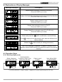
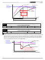
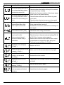
4-2 Explanations of Display Messages
Messages Displayed
Descriptions
Display master frequency command of the drive
(Press the DISP key to read)
FW D
REV
EXT
PU
Display actual operation frequency output to the motor from the drive
(Press the DISP key to read)
FW D
REV
EXT
PU
Display output current to motor
(Press the DISP key to read)
FW D
REV
EXT
PU
Display User-selected content on Pr0-07
(Press the DISP key to read)
FW D
REV
EXT
PU
Display Read/Save selected content (For PU-02 only)
(Press the DISP key to read)
The specified parameter item
(Rotate and press the PROG dial to modification, read and Enter)
FW D
REV
EXT
(Press
PU
to display those parameters which data are different from
factory default)
Value of the parameter content
(Rotate the
dial to modify for setting parameters)
RESET
PROG
FW D
REV
EXT
PU
If the “End” message is displayed , for about 1 second, it is an
indication that the data has been accepted and saved to the internal
memory.
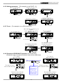
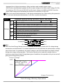
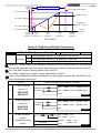
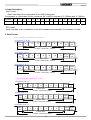
4-3 Operation Steps
4-3-1 Selecting display mode
Master frequency
command of the drive
FWD
Press
REV
EXT
PU
DISP
Actual operation
frequency output to the
motor from the drive
FWD
Press
REV
EXT
PU
FWD
DISP
User defined MultiFunction Display
Output current
to motor
Press
REV
EXT
PU
DISP
FWD
REV
EXT
Press
To scrolling between F page, H page, A page and U page by pressing the DISP key
4-2
PU
DISP
TOPVERT G1H1P1 Series
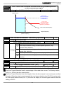
4-3-2 Setting parameters
(For example, to set Pr0-07 = 2)
E n try P a ra m e te r
g ro u p 0
FW D
REV
EXT
P re s s th e n
ro ta te
S e le c t P r 0 - 0 7 to
b e m o d if ie d
PU
FW D
REV
P re s s th e n
ro ta te
PROG
EXT
M o d if y d a t a to 2
PU
FW D
PROG
FW D
REV
EXT
4-3-3 To run
EXT
PU
PROG
D a ta h a s b e e n
a c c e p te d a n d s a v e d
B a c k to F p a g e
P re s s
t w ic e
REV
P re s s th e n
ro ta te
FW D
PU
D IS P
REV
P re s s
EXT
PU
PROG
(For example, to run 50 Hz from PU)
S e t m a s te r fr e q u e n c y to
50H z
( U s e le f t k e y fo r q u ic k
d a ta e n t r y )
T o e n a b le P U
FW D
REV
EXT
PU
FW D
PU
P re s s
REV
EXT
R o ta te
PU
FW D
PROG
T o s h if t d a t a
REV
EXT
PU
RUN
P re s s
RESET
T o d is p la y a c tu a l
o u tp u t fr e q u e n c y
to t h e m o t o r
T o s e t tin g d ir e c t io n
F W D /R E V
FW D
T o r u n s e t te d
5 0 .0 0 H z
REV
EXT
FW D
PU
F /R
P re s s
REV
EXT
PU
D IS P
P re s s
4-3-4 Parameters READ/SAVE Operation (For PU-02 only)
(Parameter copy can execute between same drive model only)
T o re a d
p a ra m e te r
FW D
REV
EXT
To save
p a ra m e te r
PU
RESET
P a ra m e te r R e a d
a c c o m p lis h e d
REV
PROG
PU
P re s s 2 k e y
s im u lta n e o u s ly
FW D
R o ta te
EXT
S e le c t:
R ead1
S ave1
R ead2
S ave2
FW D
4-3
EXT
PU
PU
P re s s 2 k e y
s im u lta n e o u s ly
RESET
P a ra m e te r S a v e
a c c o m p lis h e d
FW D
PU
REV
REV
EXT
PU
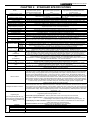
TOPVERT G1/H1/P1 Series
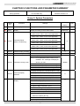
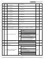
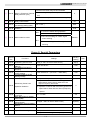
CHAPTER 5 FUNCTIONS AND PARAMETER SUMMARY
★=This parameter cannot be set
◎: Available in Firmware Version
during operation.
[ ] Parameter no. in
2.xx and after only.
Firmware Version 1.xx
Group 0: System Parameters
Parame
ters
★
Pr0-00
★ Pr0-01
Functions
Settings
Setting
Model display
Display according to the model number
Read Only
Rated Output Current
Display
Display according to the model number
Read Only
Pr0-03
Password Input (The Key)
10: Parameter reset for
60Hz, 230V / 460V / 575V motor application
9: Parameter reset for
50Hz, 220V / 380V / 575V motor application
8: Parameter reset for
60Hz, 220V / 380V / 575V motor application
7: Parameter reset for
50Hz, 230V / 460V / 575V motor application
6: Parameter reset for
60Hz, 240V / 415V / 575V motor application
5: Parameter reset for
50Hz, 240V / 415V / 575V motor application
0〜9999
Pr0-04
Password set (The Lock)
0〜9999
★ Pr0-02
Factory
Parameter Reset
(Motor V/F selecting)
8
◎
◎
0
0
Bit 0=0: All parameters are readable
Bit 0=1: Those parameters after Pr0-05 are not
readable, ”Err” message will displayed
Pr0-05
Parameter Locking Level
when try to read
b00000
Bit 1=0: Enable Frequency Command changes
Bit 1=1: Disable Frequency Command changes
Bit 2=0: Enable run command from keypad
Bit 2=1: Disable run command from keypad
0: Display the frequency command value(F)(Hz)
Pr0-06
Pr0-07
Power-up Display
Selection
Content of Multi-Function
Display
1: Display the actual output frequency (H)(Hz)
0
2: Display the output current(A)(Ampere)
3: Multifunction display (U) (display of Pr0-07)
0: Motor speed (RPM)
1: DC-BUS voltage (Vdc)
2: Output voltage (Vac)
3: Output Voltage command (Vac)
4: PID feedback signal value (Hz)
5: Multi-step speed running step no.
6: Sleep time (Pr8-07)
7: Remaining number of times for the “restart
after fault” feature (Pr6-10)
8: PIDCommand frequency (Hz)
9: (Factory Reserved)
5-1
0
User
TOPVERT G1/H1/P1 Series
10: Output Power factor angle ( º )
11: Counter value
12: Over-torque accumulated time 1 (Pr5-17)
13: (Factory Reserved)
14: Dwell Time at Accel. (Pr6-14)
15: Dwell Time at Decel. (Pr6-16)
16: DC Braking Time during Start-up (Pr6-01)
17: DC Braking Time during STOP(Pr6-02)
18: Remain time of the executing MSS Run
19: (Factory Reserved)
20: (Factory Reserved)
21: Accumulated power-up Day (day)
22: Accumulated power-up time (hh:mm)
23: (Factory Reserved)
24: (Factory Reserved)
25: (Factory Reserved)
26: The signal of AVI analog input (Vdc)
27: The signal of ACI analog input (mAdc)
28: The signal of AUI analog input (Vdc)
29: (Factory Reserved)
30: (Factory Reserved)
31: (Factory Reserved)
32: (Factory Reserved)
33: (Factory Reserved)
34: Over-torque level 1 (Pr5-16)
35: Torque compensation gain 1 (Pr5-01)
36: (Factory Reserved)
37: (Factory Reserved)
38: Stall Prevention level (Pr5-12)
39〜52: (Factory Reserved)
53: Output power (kW)
54: Output power (kVA)
55:(Factory Reserved)
56: The temperature of IGBT--OH1 ( °C)
57: The temperature of heat sink--OH2 (°C)
58: (Factory Reserved)
59: (Factory Reserved)
60: Overload accumulated time (OL)
61:(Factory Reserved)
62: Compensated voltage
63: (Factory Reserved)
64: DC Bus voltage upon a fault (Vdc)
65: Output voltage upon a fault (Vac)
66: Output frequency upon a fault (Hz)
67: OH1 value upon a fault ( °C)
68: Output current value upon a fault (Aac)
69︰OH2 value upon a fault ( °C)
70~86︰(Factory Reserved)
87: DC Bus ripple voltage (Vdc)
88: PG frequency (Hz)
Pr0-08
User-Defined Coefficient
0〜39 (no use)
Setting K
40〜60000 (the corresponding value
for Pr1-00-- the max. frequency)
5-2
◎
◎
◎
◎
0
TOPVERT G1/H1/P1 Series
Pr0-09
Number of the decimal
places
0~3
Pr0-10
Firmware Version
Read-only
0
x.xx
Bit 0 =1: FWD/REV direction command not
memorized
Bit 1 =1:PU frequency command not memorized
Pr0-11
EPROM store settings
Bit 2 =1:RS-485 frequency command not
memorized
b00000
Bit 3 =1:Up/down frequency command not
memorized
Bit 4 =1:Changed parameter not memorized
0: Linear acceleration/deceleration
(Auto accel./decal. disabled)
1: Auto acceleration, linear deceleration
Pr0-12
Optimal Acceleration /
Deceleration Setting
2: Linear acceleration, auto deceleration
3: Auto acceleration/deceleration
0
4: Linear acceleration/deceleration, but conduct
the stall prevention throughout the auto
acceleration/deceleration function.
0: Unit: 0.01 Sec
★
Pr0-13
Time unit for Acceleration
Deceleration and S curve
1: Unit: 0.1 Sec
0
2: Unit: 1 Sec
Pr0-14
Pr0-15
Carrier Frequency Upper
Bound
Carrier Frequency Lower
Bound
0=0.7kHz
1〜18kHz
0=0.7kHz
1〜18kHz
10
10
0: AVR function enabled
Pr0-16
Automatic Voltage
Regulation (AVR)
1: AVR function disabled
0
2: AVR function disabled during deceleration
Bit 0=0: Disable AESO
Bit 0=1: Enable AESO
Bit 1=0: Maximum output voltage could be higher
than the source voltage
Automatic Energy-Saving
Pr0-17
Operation (AESO) and
others
Bit 1=1: Maximum output voltage equals to the
source voltage
Bit 2=0: General purpose constant torque
application.
Bit 2=1: Fan and pump variable torque
application .
Bit 3=0: Regen torque without slip compensation
Bit 3=1: Regen torque with slip compensation
Bit 4=0: Low noise mode operation
Bit 4=1: Quiet mode operation
5-3
b00000
TOPVERT G1/H1/P1 Series
0: The digital keypad (PU)
1: The RS485 communication port
2: The external analog signal
Pr0-18
Source of the Master
Frequency Command
0
3: The external up/down terminals
(multi-function input terminals)
4: The Pulse input
(A PG Feedback Card (optional) is necessary.)
◎
0: RS485 serial communication or Digital keypad
Pr0-19
Source of the Operation
Command
(PU)
1: External terminals or Digital keypad (PU)
0
2: Digital keypad (PU)
3: External terminals
Bit 0=0: Ramp to stop
Bit 0=1: Coast to stop
Bit 1=0: Not restart after reset
Bit 1=1: Restart after reset
Bit 2=0: Line Start Lockout is enabled
Pr0-20
Stop Methods and Run
safety lockout
Bit 2=1: Line Start Lockout is disabled
b00000
Bit 3=0: The transition between FWD/REV going
through 0 point
Bit 3=1: The transition between FWD/REV not
going through 0 point
Bit 4=0: linear accel and decel at high speed zone
Bit 4=1: S-curve accel and decel at high speed
zone
0: Enable Forward/Reverse operation
Pr0-21
Reverse Operation
1: Disable Reverse operation
0
2: Disabled Forward operation
Pr0-22
Timer After stopped
0.00
0.00~60.00sec
Bit 0=0:when power is applied,
Pr0-23
Fan control
the fan will turn on
Bit 0=1:When the run command is given,
b00000
the fan will turn on
★
◎
Pr0-24
Frequency setting
resolution of Fly-shuttle
dial on PU
Pr0-25
Parameter Team
selection
0=0.01 Hz
1=0.10Hz
2=1.00Hz
3=10.00 Hz
0: Team A
1: Team B
2: Select Team A or Team B by MI3
5-4
1
0
TOPVERT G1/H1/P1 Series
Group 1: Basic Parameters
Parame
ters
★ Pr1-00
★ Pr1-01
Pr1-02
★ Pr1-03
Pr1-04
★ Pr1-05
Pr1-06
Factory
Functions
Settings
Maximum Operation Frequency
50.0〜600.00Hz (H1:50.00 〜6000.00Hz)
60.00/50.00
0.00〜600.00 Hz (H1:00.00 〜6000.00Hz)
60.00/50.00
230V
models:
0.0〜255.0V
230V:230.0
460V:460.0
575V:575.0
1st Frequency Setting 1
(Base Frequency) (FBASE 1)
1st Voltage Setting 1
(Motor rated voltage) (VBASE 1)
2nd Frequency Setting 1
(Middle Frequency 1) (FMID 1)
2nd Voltage Setting 1
(Middle Voltage 1) (VMID 1)
3rd Frequency Setting 1
(Low-point Frequency 1) (FLOW 1)
3rd Voltage Setting 1
(Low-point Voltage 1)(VLOW 1)
460V
models:
0.0〜510.0V
Setting
◎ 575V
models:
0.0〜637.5V
0.00〜600.00 Hz (H1:00.00 〜6000.00Hz)
230V
models:
0.0〜255.0V
460V
models:
0.0〜510.0V
◎ 575V
models:
0.0〜637.5V
0.00〜600.00 Hz (H1:00.00 〜6000.00Hz)
230V
models:
0.0〜255.0
460V
models:
0.0〜510.0V
◎ 575V
models:
0.0〜637.5V
230V
460V
◎ 575V
models:
models:
models:
0.0〜255.0
0.0〜510.0V 0.0〜637.5V
0.00〜600.00 Hz (H1:00.00 〜6000.00Hz)
0.50
230V:5.0
460V:10.0
575V:12.5
0.50
230V:5.0
460V:10.0
575V:12.5
Pr1-07
0Hz Output Voltage Setting 1
(V0Hz 1)
Pr1-08
Startup Frequency
Pr1-09
Output Frequency Upper Limit
Pr1-10
Output Frequency Lower Limit
Pr1-11
Acceleration Time 1
0.00〜60000 Sec
10.00/60.00
1-12
Deceleration Time 1
0.00〜60000 Sec
10.00/60.00
Pr1-13
Acceleration Time 2
0.00〜60000 Sec
10.00/60.00
Pr1-14
Deceleration Time 2
0.00〜60000 Sec
10.00/60.00
Pr1-15
JOG Acceleration Time
0.00〜60000 Sec
10.00/60.00
Pr1-16
JOG Deceleration Time
0.00〜60000 Sec
10.00/60.00
Pr1-17
JOG Frequency
0.00〜600.00 Hz (H1:00.00 〜6000.00Hz)
6.00
0.00〜600.00 Hz (H1:00.00 〜6000.00Hz)
0.000
0.00〜12000 Sec
0.00
0.00〜12000 Sec
0.00
0.00〜12000 Sec
0.00
0.00〜12000 Sec
0.00
Pr1-18
Pr1-19
Pr1-20
Pr1-21
Pr1-22
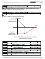
1st/2nd Acceleration/Deceleration
Frequency
0.0〜150.0% of Maximum Operation
Frequency (Pr1-00)
0.0〜100.0% of Maximum Operation
Frequency (Pr1-00)
S-Curve for Acceleration
Departure Time
S-Curve for Acceleration Arrival
Time
S-Curve for Deceleration
Departure Time
S-Curve for Deceleration Arrival
Time
5-5
0.0
0.50
110.0
0.0
User
TOPVERT G1/H1/P1 Series
Pr1-23
[Pr1-29]
★
★
★
★
★
★
★
◎
★
◎
★
◎
★
◎
★
◎
★
◎
★
◎
◎
★
◎
★
◎
★
◎
★
◎
★
◎
Pr1-24
Offset voltage at decel
230V
models:
460V
models:
575V
models:
-50.0~50.0 V
-100.0~100.0 V
-125.0~125.0 V
0.00
Skip Frequency 1 upper limit
0.00~600.00Hz (H1:0.00~6000.00Hz)
0.00
Skip Frequency 1 lower limit
0.00~600.00Hz (H1:0.00~6000.00Hz)
0.00
Skip Frequency 2 upper limit
0.00~600.00Hz (H1:0.00~6000.00Hz)
0.00
Skip Frequency 2 lower limit
0.00~600.00Hz (H1:0.00~6000.00Hz)
0.00
Skip Frequency 3 upper limit
0.00~600.00Hz (H1:0.00~6000.00Hz)
0.00
Skip Frequency 3 lower limit
0.00~600.00Hz (H1:0.00~6000.00Hz)
0.00
Pr1-30
Skip Frequency 4 upper limit
0.00〜600.00 Hz (H1:00.00 〜6000.00Hz)
0.00
Pr1-31
Skip Frequency 4 lower limit
0.00〜600.00 Hz (H1:00.00 〜6000.00Hz)
0.00
Pr1-32
Skip Frequency 5 upper limit
0.00〜600.00 Hz (H1:00.00 〜6000.00Hz)
0.00
Pr1-33
Skip Frequency 5 lower limit
0.00〜600.00 Hz (H1:00.00 〜6000.00Hz)
0.00
Pr1-34
Skip Frequency 6 upper limit
0.00〜600.00 Hz (H1:00.00 〜6000.00Hz)
0.00
Pr1-35
Skip Frequency 6 lower limit
0.00〜600.00 Hz (H1:00.00 〜6000.00Hz)
0.00
0.00〜600.00 Hz (H1:00.00 〜6000.00Hz)
60.00/50.00
[Pr1-23]
Pr1-25
[Pr1-24]
Pr1-26
[Pr1-25]
Pr1-27
[Pr1-26]
Pr1-28
[Pr1-27]
Pr1-29
[Pr1-28]
Pr1-36
Pr1-37
Pr1-38
Pr1-39
Pr1-40
Pr1-41
Pr1-42
1st Frequency Setting 2
(Base Frequency) (FBASE 2)
1st Voltage Setting 2
(Motor rated voltage) (VBASE 2)
2nd Frequency Setting 2
(Middle Frequency 2) (FMID 2)
2nd Voltage Setting 2
(Middle Voltage 2) (VMID 2)
3rd Frequency Setting 2
(Low-point Frequency 2) (FLOW 2)
230V
460V
575V
models:
models:
models:
0.0〜255.0V
0.0〜510.0V
0.0〜637.5V
0.00〜600.00 Hz (H1:00.00 〜6000.00Hz)
230V
460V
575V
models:
models:
models:
0.0〜255.0V
0.0〜510.0V
0.0〜637.5V
0.00〜600.00 Hz (H1:00.00 〜6000.00Hz)
3rd Voltage Setting 2
230V model:
460V model:
575Vmodels:
(Low-point Voltage 2) (VLOW 2)
0.0〜255.0V
0.0〜510.0V
0.0〜637.5V
0Hz Output Voltage Setting 2
230V model:
460V model:
575V models:
(V0Hz 2)
0.0〜255.0V
0.0〜510.0V
0.0〜637.5V
5-6
230V:230
460V:460
575V:575
0.50
230V:5.0
460V:10.0
575V:12.5
0.50
230V:5.0
460V:10.0
575V:12.5
0.0
TOPVERT G1/H1/P1 Series
Group 2: Digital Input/Output Parameters
Parame
Functions
ters
Settings
Factory
Setting
0: 2-wire operation control (1):
FWD/STOP, REV/STOP
★ Pr2-00
2-Wire/3-Wire Operation
Control
1: 2-wire operation control (2):
0
RUN/STOP, REV/FWD
2: 3-wire Operation (momentary push button)
★ Pr2-01
★ Pr2-02
★ Pr2-03
★ Pr2-04
★ Pr2-05
★ Pr2-06
Multi-Function Digital Input
Command 1 (MI1)
Multi-Function Digital Input
Command 2 (MI2)
Multi-Function Digital Input
Command 3 (MI3)
Multi-Function Digital Input
Command 4 (MI4)
Multi-Function Digital Input
Command 6 (MI6)
Multi-Function Input
Command 6 (MI6)
0: No definition
1
1: Multi-step speed command 1
2
2: Multi-step speed command 2
3
3: Multi-step speed command 3
4
4: Multi-step speed command 4
5
5: External Reset (NO)
14
6: Clear counter
7: The 1st, 2nd acceleration/ deceleration time
selection
8: Acceleration/deceleration speed inhibit
9: Frequency command from AVI
10: Frequency command from ACI
11: Frequency command from AUI
12: Emergency Ramp Stop
13: PID function disabled
14: EF input (External fault input terminal)
15: B.B. traces from the bottom upward
16: B.B. traces from the top downward
17: Operation command from External terminal.
18: Cancel the setting of the optimal
acceleration/ deceleration time
19: FWD JOG command
20: REV JOG command
21: JOG command
22: Cancel PLC Run
23: Pause PLC Run
24: Digital Up command
25: Digital Down command
26: Zero speed is replaced by DC braking
27: Pause
28: Disable Dwell function
5-7
User
TOPVERT G1/H1/P1 Series
29: Disable traverse function
30: Disable Speed Search during Start-up
31: EEPROM write function disable
32: Counter Trigger (MI2 terminal only)
42: Motor Selection
◎
43: Confirm signal of Motor selection
◎
0: Up command,drive accel according to
Bit 0
Accel time
1: Up command, drive accel according to
Pr2-08 setting
0: Down command,drive decel according
Bit 1
to Decel time
1: Down command, drive decel ccording
to Pr2-08 setting
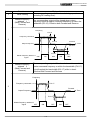
Pr2-07
The Acceleration
/Deceleration mode of the
UP/DOWN command
Bit 2
(Factory Reserved)
b00000
0: FWD/REV terminals action by Edge
Bit 3
Trigger
1: FWD/REV terminals action by Level
Trigger
0: PG feed-back over compensation
Bit 4
during Accel is allow
1: PG feed-back over compensation
during Accel is not allow
The specific Acceleration
Pr2-08
/Deceleration of the
0.01〜1.00Hz/msec (10〜1000Hz/sec)
0.01
0.001〜30.000 Sec
0.005
UP/DOWN command
Pr2-09
Digital Input Terminal
Debouncing Time
Digital Input terminals status
00000~000FF
select
0=Short circuit active 1=Open circuit active
Pr2-11
Terminal Count Value
0〜65500
0
Pr2-12
Preliminary Count Value
0〜65500
0
Pr2-13
Digital Pulse Output Gain
1~20
1
Pr2-14
Pre-set Arrival Frequency 1
0.00〜600.00 Hz (H1:00.00 〜6000.00Hz)
60.00/50.00
0.00〜600.00 Hz (H1:00.00 〜6000.00Hz)
2.00
0.00〜600.00 Hz (H1:00.00 〜6000.00Hz)
60.00/50.00
0.00〜600.00 Hz (H1:00.00 〜6000.00Hz)
2.00
Bit 0〜Bit 3 separate setting as table in below
b00000
Pr2-10
Pr2-15
Pr2-16
Pr2-17
Pr2-18
Pre-set Arrival Frequency 1
band width
Pre-set Arrival Frequency 2
Pre-set Arrival Frequency 2
band width
Multi-Function Output
Direction
5-8
h00000
TOPVERT G1/H1/P1 Series
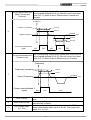
◎ Pr2-19
Delay time of Multi-Function
Output terminals
Pr2-20
Multi-Function Output 1
[Pr2-19]
(Relay 1)
Pr2-21
Multi-Function Output 2
(Relay 2)
Multi-Function Output 3
(MO1)
Multi-Function Output 4
(MO2)
[Pr2-20]
Pr2-22
[Pr2-21]
Pr2-23
[Pr2-22]
0.000~60.000 Sec
0.003
1: Drive running
11
2: Master frequency attained 1
(Both Forward and Reverse)
3: Master frequency attained 2
(Both Forward and Reverse)
4: Pre-set speed attained 1
(Both Forward and Reverse)
5: Pre-set speed attained 1 (Forward only)
6: Pre-set speed attained 2
(Both Forward and Reverse)
7 : Pre-set speed attained 2 (Forward only)
1
5
9
8: Drive in decel
9: Drive ready for use
10: Low voltage alarm (LU, LUr)
11: Fault Indication
12: Base block (B.B.) Indication
13: Zero Speed (including shutdown)
14: Zero speed (while in run)
15: Terminal Count Value Attained
16: Preliminary Count Value Attained
17: PLC Run running
18: PLC Run paused
19: A step of PLC Run completed
20: PLC Run completed
21: IGBT over-heat indication (oH1)
22: Dwell Accel/Decel interruption
23: Operation Mode indication
24: Over-torque 1 (ot1)
25: Digital frequency signal output (only MO2)
26: Software braking output (MO1, Pr2-22 only)
27: Auxiliary Motor no. 1
28: Auxiliary Motor no. 2
29: Auxiliary Motor no. 3
30: Over-torque 2 (ot2)
◎
31: Heatsink over-heat indication (oH2)
◎
32: Motor selection output (Pr5-49)
48~63: PLC Run step indication
5-9
◎
TOPVERT G1/H1/P1 Series
Group 3: Analog Input/Output Parameters
Parame
Functions
ters
Pr3-00
Pr3-01
Settings
Addition Function of the Analog
0: enable addition function
Inputs
1: disable addition function (AVI,ACI, AUI)
Analog Input Noise Filter
0.00~2.00 sec
Factory
Setting
0
0.10
0: No functions
Pr3-02
ACI
1: Frequency command
2: Acceleration/deceleration time gain
(increase or decrease time base)
(Pr3-0
6)
3: Over-current stall prevention level during
and
operation
AUI
4: Over-current stall prevention level during
Acceleration
(Pr3-1
5: Over-torque current level
1)
6: Torque compensation gain
AVI Analog Input
(External Analog command)
7: AVI auxiliary frequency
(multiplication by the ratio of AVI)
1
8: ACI auxiliary frequency
(multiplication by the ratio of ACI)
9: AUI auxiliary frequency
(multiplication by the ratio of AUI)
10: Auxiliary frequency of master frequency
11: PID feedback signal
12: PID offset signal
13: DC Braking Current Level (same as Pr6-00)
14: Torque adjust during run. (AVI Pr3-02 only)
15: External temperatures signal
Pr3-03
AVI Analog Input Bias
-10.00〜10.00V
0.00
Pr3-04
AVI Analog Input Gain
-500.0〜+500.0%
100.0
0: zero bias
1: value lower than bias = bias
Pr3-05
AVI Positive/Negative Bias
Mode
2: value higher than bias = bias
0
3: he absolute value of the bias voltage while
serving as the center
Pr3-06
ACI Analog Input
Same as Pr3-02
0.00
Pr3-07
ACI Analog Input Bias
0.00〜20.00mA
4.00
Pr3-08
ACI Analog Input Gain
-500.0〜+500.0%
100.0
0:zero bias
Pr3-09
ACI Positive/Negative Bias
Mode
1: value lower than bias = bias
2: value higher than bias = bias
3: the absolute value of the bias voltage while
5-10
1
User
TOPVERT G1/H1/P1 Series
serving as the center
0: disabled
1: Continue operation by the last frequency comman
2: Decelerate to stop
3: Coast to stop and display AcI
0
Pr3-10
Loss of the ACI signal
Pr3-11
AUI Analog Input
(Same as Pr3-02)
0.00
Pr3-12
AUI Analog Input Bias
-10.00〜10.00V
0.00
Pr3-13
AUI Analog Input Gain
-500.0〜+500.0%
100
0: zero bias
1: value lower than bias = bias
Pr3-14
AUI Positive/Negative Bias
Mode
2: value higher than bias = bias
0
3: the absolute value of the bias voltage while
serving as the center
Pr3-15
AVO Analog Output 1 Selection
0: Output frequency (Hz)
0
1: Command frequency (Hz)
2: Motor Speed
3: Output current (A rms)
4: Output voltage (VAC)
5: DC BUS voltage (VDC)
6: Power factor
Pr3-16
ACO Analog Output 2
Selection
7: Power
0
8: AVI (V)
9: ACI (mA)
10: AUI (V)
13: Voltage command
14: Counter Value
15: Analog Output Value
Pr3-17
AVO Analog Output Gain
-900.0〜900.0%
100.0
Pr3-18
ACO Analog Output Gain
-900.0〜900.0%
80.0
-10.00〜10.00V
0.00
0.00〜20.00mA
4.00
0.0〜100.0%
0.0
Pr3-19
Pr3-20
Pr3-21
AVO Analog Output Bias
Voltage
ACO Analog Output Bias
Current
Analog Output Value
Group 4: Multi-Step Speed and Process Logic Control Operation Parameters
Parame
ters
Pr4-00
Pr4-01
Pr4-02
Functions
The 1st Step Speed Frequency
of PLC Run or MSS Run
The 2nd Step Speed Frequency
of PLC Run or MSS Run
The 3rd Step Speed Frequency
of PLC Run or MSS Run
Settings
Factory
Setting
0.00〜600.00 Hz (H1:00.00 〜6000.00Hz)
0.00
0.00〜600.00 Hz (H1:00.00 〜6000.00Hz)
0.00
0.00〜600.00 Hz (H1:00.00 〜6000.00Hz)
0.00
5-11
User
TOPVERT G1/H1/P1 Series
Pr4-03
Pr4-04
Pr4-05
Pr4-06
Pr4-07
Pr4-08
Pr4-09
Pr4-10
Pr4-11
Pr4-12
Pr4-13
Pr4-14
Pr4-15
Pr4-16
Pr4-17
Pr4-18
Pr4-19
Pr4-20
Pr4-21
Pr4-22
The 4th Step Speed Frequency
of PLC Run or MSS Run
The 5th Step Speed Frequency
of PLC Run or MSS Run
The 6th Step Speed Frequency
of PLC Run or MSS Run
The 7th Step Speed Frequency
of PLC Run or MSS Run
The 8th Step Speed Frequency
of PLC Run or MSS Run
The 9th Step Speed Frequency
of PLC Run or MSS Run
The 10th Step Speed Frequency
of PLC Run or MSS Run
The 11th Step Speed Frequency
of PLC Run or MSS Run
The 12th Step Speed Frequency
of PLC Run or MSS Run
The 13th Step Speed Frequency
of PLC Run or MSS Run
The 14th Step Speed Frequency
of PLC Run or MSS Run
The 15th Step Speed Frequency
of PLC Run or MSS Run
Time Duration of the PLC Run
Master Speed
The 1st Step Duration of PLC
Run or MSS Run
The 2ndStep Duration of PLC
Run or MSS Run
The 3rd Step Duration of PLC
Run or MSS Run
The 4th Step Duration of PLC
Run or MSS Run
The 5th Step Duration of PLC
Run or MSS Run
The 6th Step Duration of PLC
Run or MSS Run
The 7th Step Duration of PLC
Run or MSS Run
0.00〜600.00 Hz (H1:00.00 〜6000.00Hz)
0.00
0.00〜600.00 Hz (H1:00.00 〜6000.00Hz)
0.00
0.00〜600.00 Hz (H1:00.00 〜6000.00Hz)
0.00
0.00〜600.00 Hz (H1:00.00 〜6000.00Hz)
0.00
0.00〜600.00 Hz (H1:00.00 〜6000.00Hz)
0.00
0.00〜600.00 Hz (H1:00.00 〜6000.00Hz)
0.00
0.00〜600.00 Hz (H1:00.00 〜6000.00Hz)
0.00
0.00〜600.00 Hz (H1:00.00 〜6000.00Hz)
0.00
0.00〜600.00 Hz (H1:00.00 〜6000.00Hz)
0.00
0.00〜600.00 Hz (H1:00.00 〜6000.00Hz)
0.00
0.00〜600.00 Hz (H1:00.00 〜6000.00Hz)
0.00
0.00〜600.00 Hz (H1:00.00 〜6000.00Hz)
0.00
0.0〜65500 Sec
0.0
0.0〜65500 Sec
0.0
0.0〜65500 Sec
0.0
0.0〜65500 Sec
0.0
0.0〜65500 Sec
0.0
0.0〜65500 Sec
0.0
0.0〜65500 Sec
0.0
0.0〜65500 Sec
0.0
5-12
TOPVERT G1/H1/P1 Series
Pr4-23
Pr4-24
Pr4-25
Pr4-26
Pr4-27
Pr4-28
Pr4-29
Pr4-30
Pr4-31
Pr4-32
The 8th Step Duration of PLC
Run or MSS Run
The 9th Step Duration of PLC
Run or MSS Run
The 10th Step Duration of PLC
Run or MSS Run
The 11th Step Duration of PLC
Run or MSS Run
The 12th Step Duration of PLC
Run or MSS Run
The 13th Step Duration of PLC
Run or MSS Run
The 14th Step Duration of PLC
Run or MSS Run
The 15th Step Duration of PLC
Run or MSS Run
The PLC Run or MSS Run Time
Multiplier
The PLC Run or MSS Run
Operation Direction
0.0〜65500 Sec
0.0
0.0〜65500 Sec
0.0
0.0〜65500 Sec
0.0
0.0〜65500 Sec
0.0
0.0〜65500 Sec
0.0
0.0〜65500 Sec
0.0
0.0〜65500 Sec
0.0
0.0〜65500 Sec
0.0
1
1〜10
00000~07FFF(0:forward;1:reverse)
0: direction determined by Pr4-32
1: direction determined by the master
speed
0: Without zero intervals (Continue mode)
Bit 1
1: With zero intervals (Stop mode)
0: Run zero speed when PLC Run Paused
Bit 2 1: Run original programmed step speed
when PLC Run Paused
0: Re-Execute PLC Run from step 0 after
recover from power interruption
Bit 3 1: Continue Execute PLC Run from the
point which power interruptied after
recover from power interruption
0: PLC Run disabled
1~60000 : 1~60000 cycle
60001: Continuously execute program cycles
h00000
Bit 0
Pr4-33
PLC Run Operation Mode
Pr4-34
PLC Run operation Cycle
Pr4-35
What to do after PLC Run
0~15:step speed (0=master speed)
completed
16:stop
Bit 0
Pr4-36
Multi-Step Speed Run (MSS
RUN) Operation Mode
Bit 1
Bit 2
Bit 3
0: Direction determined by Pr4-32
1: Direction determined by the master
speed
0: Duration of MSS Run determined by
Mix terminals.
1: Duration of MSS Run determined by
Pr4-15~Pr4-30 setting.
0: Without zero intervals (Continue mode)
1: With zero intervals (Stop mode)
0: PID offset disabled
1: MSS Run + PID offset
5-13
b00000
0
16
b00001
TOPVERT G1/H1/P1 Series
Group 5: Motor Parameters and Protection Parameters
Parame
Functions
ters
★ Pr5-00
Pr5-01
Pr5-02
Pr5-03
Pr5-04
Full-Load Current of Motor 1
Auto Torque Compensation
of Motor 1
Slip Compensation of Motor
1
Number of Motor Poles 1
Rotor Resistance R1 of
Motor 1
★ Pr5-05
Auto-tuning & control mode
selection
★ Pr5-06
Low Voltage Level l
★ Pr5-07
Pr5-08
Over-Voltage Stall
Prevention Level
Software Braking Level
Settings
Amp (10~120% of drive’s rated current)
Factory
Setting
xxxA
(100%)
0.0〜25.0%
0.0
0〜60 RPM
0
2〜20
4
0.0〜6553.5 mΩ
0
0: No function
1: To execute auto-tuning and switch to
Sensorless vector control mode
2: Reset to V/F control mode
230V
460V
◎ 575V
models:
models:
models:
160〜220VAC
320〜440VAC
400〜550VAC
◎ 575V
230V
460V
models:
models:
models:
320〜500VDC 640〜1000VDC 800〜1250VDC
◎ 575V
230V
460V
models:
models:
models:
320〜500VDC 640〜1000VDC 800〜1250VDC
0
230V:180
460V:360
575V:450
230V:380
460V:760
575V:950
230V:373
460V:746
575V:932
0: Warn and keep operation (below 50%)
Pr5-09
Phase-Loss Protection
1: Warn and ramp to stop
0
2: Warn and coast to stop
Over- Current Stall
Pr5-10
Prevention level during
accel on the constant torque
Amp (10~250% of drive’s rated current)
A(170%)
Amp (0~250% of drive’s rated current)
A(120%)
Amp (10~250% of drive’s rated current)
A(170%)
Amp (0~250% of drive’s rated current)
A(120%)
region
Over- Current Stall
Pr5-11
Prevention low-limit level
during accel on the constant
power region
Over-Current Stall
Prevention level during
Pr5-12
constantant speed on the
constant torque region
Operation
Over- Current Stall
Prevention low-limit level
Pr5-13
during constant speed run
on the constant power
region
5-14
User
TOPVERT G1/H1/P1 Series
Pr5-14
Pr5-15
Pr5-16
Pr5-17
Pr 5-18
Pr5-19
Pr5-20
Over-Current Deceleration
Time during Operation
0.050~600.00 Sec
Over-Torque Detection
Selection 1 (ot1)
0:Disabled
1:Over-torque detection during constant speed
operation, stop operation after detection.
2:Over-torque detection during constant speed
operation, continue to operate after detection.
3:Over-torque detection during operation, stop
operation after detection
4:Over-torque detection during operation,
continue operation after detection.
Over-Torque Detection
Level 1 (ot1)
Over-Torque Detection
Time 1 (ot1)
Motor 1- Electronic Thermal
Relay Selection (oL1)
Motor 1- Electronic Thermal
Relay Characteristic
IGBT Over-Heat
pre–warning setting (oH2)
Amp(20〜250% of drive’s rated current)
0.0〜60.0 Sec
3.00
0
A(150%)
0.1
0:Electronic thermal relay function disabled
1:Inverter duty motor
(with independent cooling fan)
2:Standard motor (with shaft mounted cooling fan)
0
30〜600 Sec
60
0.0~110.0
85.0
0: Disabled
1: Over-torque detection during constant speed
operation, stop operation after detection.
2: Over-torque detection during constant speed
Pr5-21
Pr5-22
Pr5-23
Pr5-24
[Pr5-21]
Pr5-25
[Pr5-22]
Pr5-26
[Pr5-23]
Pr5-27
[Pr5-24]
◎ Pr5-28
◎ Pr5-29
◎ Pr5-30
◎ Pr5-31
◎ Pr5-32
◎ Pr5-33
Over-Torque Detection
Selection 2 (ot2)
Over-Torque Detection
Level 2 (ot2)
Over-Torque Detection
Time 2 (ot2)
Most Recent Fault Record
2nd Most Recent Fault
Record
3rd Most Recent Fault
Record
4th Most Recent Fault
Record
5th Most Recent Fault
Record
6th Most Recent Fault
Record
7th Most Recent Fault
Record
8th Most Recent Fault
Record
9th Most Recent Fault
Record
10th Most Recent Fault
Record
operation, continue to operate after detection.
3: Over-torque detection during entire
(acceleration, steady state, deceleration)
operation, stop operation after detection
4: Over-torque detection during entire
(acceleration, steady state, deceleration)
operation, continue operation after detection.
Amp(20〜250% of drive’s rated current)
0.0〜60.0 Sec
0
A(150%)
0.1
0
0: no fault
1: oC (over-current)
2: oU (over-voltage)
3: GF (ground fault)
4: SC (IGBT failure)
5: oL (drive overload)
6: oL1 (electronic thermal relay 1)
7: ot1 (Over-Torque1)
8: oCn (over-current during constant speed)
9: oCA (over-current during accel.)
5-15
TOPVERT G1/H1/P1 Series
◎ Pr5-34
◎ Pr5-35
◎ Pr5-36
◎ Pr5-37
◎ Pr5-38
◎ Pr5-39
11th Most Recent Fault
Record
12th Most Recent Fault
Record
13th Most Recent Fault
Record
14th Most Recent Fault
Record
15th Most Recent Fault
Record
16th Most Recent Fault
Record
10: oCd (over-current during decel.)
11: EP1 (EPROM error 1)
12: EP2 (EPROM error 2)
13: EF (external fault)
14: Ct1 (current sensor 1)
15: Ct2 (current sensor 2)
16: HPF (protection circuit fault)
17: oH1 (IGBT overheat)
18: oH2 (Heatsink overheat)
19: SoFt (Pre-charge circuit error)
20: ACI. (ACI error)
21: ASC (RS-485 error)
22: PI.d (PID error)
23: Pu(Keypad communication overtime)
24: tunE (Auto tuning failure)
25: bF (braking chopper failure)
26: PG (PG error)
27: PHL (Phase loss)
28: CC (current signal error during stop)
29: CPu (CPU error)
30: FAn (Fan failure)
31: AnI fault (Analog input error)
32: ot2 (Over-Torque2)
◎
33: oL2 (electronic thermal relay 2)
◎
34: rnot (Motor selection error)
◎
36: LUr (Low Voltage during Run)
◎
37: oUd (over-voltage during decel)
38: `x CoPY (Parameter copy error)
◎
39: LU (Low Voltage)
40: bb (External Base Block )
★
Pr5-40
◎
◎ Pr5-41
◎ Pr5-42
◎ Pr5-43
◎ Pr5-44
Full-Load Current of Motor 2
Auto Torque Compensation
of Motor 2
Slip Compensation of Motor
2
Number of Motor Poles 2
Rotor Resistance R1 of
Motor 2
Amp (10~120% of drive’s rated current)
xxxA
(100%)
0.0〜25.0%
0.0
0〜60 RPM
0
2〜20
4
0.0〜6553.5 mΩ
0
5-16
TOPVERT G1/H1/P1 Series
0: Electronic thermal relay function disabled
◎
Pr5-45
Motor 2- Electronic Thermal
Relay Selection (oL2)
1: Inverter duty motor (with independent cooling
fan)
0
2: Standard motor (with shaft mounted cooling fan)
◎
Pr5-46
◎
Pr5-47
◎
Pr5-48
Motor 2- Electronic Thermal
Relay Characteristic
Heatsink
Over-Heat
pre–warning setting (oH2)
Delay Time for Motor
Selection
30〜600 Sec
60
0.0〜110.0 ℃
85.0
0.00~60.00 Sec
0.05
Bit 0
◎
Pr5-49
0: Cannot be switch during operation.
1: Can be switch during operation.
0: No need to waiting for confirm signal
Motor selection mode
Bit 1
when swiching
b00000
1: Need to waiting for confirm signal when
swiching
Group 6: Special Parameters
Parame
ters
Pr6-00
Pr6-01
Pr6-02
Pr6-03
Pr6-04
Pr6-05
Functions
DC Braking Current Level
DC Braking Time during
Start-up
DC Braking Time during
stopping
Start-point for DC Braking
during stopping
Increasing Rate of the DC
Braking Voltage
Momentary Power Loss
Operation Selection
Settings
Amp (0~125% of drive’s rated current)
Factory
Setting
A(0%)
0.00〜60.00 Sec
0.00
0.00〜60.00 Sec
0.00
0.00〜600.00 Hz (H1:00.00 〜6000.00Hz)
0.00
0.01~300.00%
0:Operation stops after momentary power loss.
1:Operation continues after momentary power loss,
speed search Speed Search starts with Last
Output Frequency Downward
2:Operation continues after momentary power loss,
50.00%
0
speed search starts with the Start-up frequency
Upward
Pr6-06
Pr6-07
Pr6-08
Pr6-09
Maximum Allowable Power
Loss Time
Base-Block Time for Speed
Search (BB)
Maximum Current Level for
Speed Search
Deceleration Time for Speed
Search
0.1〜5.0 Sec
2.0
0.1〜5.0 Sec
0.5
Amp(20〜200% of drive’s rated current)
0.50〜120.00 Sec
A(120%)
3.00
Pr6-10
Auto Restart after Fault
0〜10 times
0
Pr6-11
Speed Search during Start-up
0:speed search disabled
0
1:speed search through the frequency command
5-17
User
TOPVERT G1/H1/P1 Series
2:FWD-speed search only
(motor only runs in FWD direction)
3:REV-speed search only
(motor only runs in REV direction)
4:FWD/REV speed search enabled in both
directions (FWD first)
5:REV/FWD speed search enabled in both
directions (REV first)
Pr6-12
Pr6-13
Speed Search Frequency
(FWD direction)
Speed Search Frequency
(REV direction)
0.00〜600.00 Hz (H1:00.00 〜6000.00Hz)
60.00/50.00
0.00〜600.00 Hz (H1:00.00 〜6000.00Hz)
60.00/50.00
Pr6-14
Dwell Time at Accel.
0.00~60.00 Sec
0.00
Pr6-15
Dwell Frequency at Accel.
0.00〜600.00 Hz (H1:00.00 〜6000.00Hz)
6.00
Pr6-16
Dwell Time at Decel.
0.00~60.00 Sec
0.00
Pr6-17
Dwell Frequency at Decel.
0.00〜600.00 Hz (H1:00.00 〜6000.00Hz)
6.00
Pr6-18
Dwell Frequency current
Amp (0~150% of rated current)
Pr6-19
Traverse Skip Frequency
0.00~100.00Hz
0.00
Pr6-20
The Amplitude of traverse
0.00~200.00Hz
0.00
A(0%)
Group 7: High-function Parameters (PID and Communication)
Parame
Functions
ters
Settings
Factory
Setting
Pr7-00
Proportional Gain (P)
0.0〜500.0%
80.0
Pr7-01
Integral Time (I)
0.00〜100.00 Sec
0.00:no integral
1.00
Pr7-02
Derivative Control (D)
0.00〜5.00 Sec
0.00
Pr7-03
Upper limit for Integral Control
0.0〜100.0%
100.0
Pr7-04
PID Output Frequency Limit
0.0〜100.0%
100.0
Pr7-05
PID Offset
-100.0~+100.0%
0.0
Pr7-06
Primary Delay Filter Time
0.000~0.100 Sec
0.000
Pr7-07
PID Feedback Signal Detection Time
0.0〜6000.0 Sec
0.0
Treatment of the Erroneous PID
0: warn and keep operating
1: warn and RAMP to stop
Feedback Signals
2: warn and COAST to stop
Pr7-9
Treatment of Keypad Transmission
Fault
0: Warn and RAMP to stop
Pr7-10
Keypad Transmission Fault detection
0.0: Disable and keep operating
0.1~60.0 Sec
Pr7-11
Communication Address
1〜254
Pr7-12
Transmission Speed (Baud rate)
1.2〜125 Kbps
Pr7-13
Transmission Fault Treatment
0: warn and keep operating
Pr7-08
1: Warn and COAST to stop
1: warn and RAMP to stop
5-18
0
0
0.0
1
9.6
3
User
TOPVERT G1/H1/P1 Series
2: warn and COAST to stop
3: No warning and keep operating
Pr7-14
Time-out Detection
0.0: disabled
0.1~60.0 Sec
0:7,N,2 ASCII
0.0
1:7,E,1 ASCII
2:7,O,1 ASCII
3:7,E,2 ASCII
4:7,O,2 ASCII
5:8,N,1 ASCII
6:8, N,2 ASCII
7:8,E,1 ASCII
Pr7-15
Communication Protocol
8:8,O,1 ASCII
0
9:8,E,2 ASCII
10:8,O,2 ASCII
11:8,N,1 RTU
12:8,N,2 RTU
13:8,E,1 RTU
14:8,O,1 RTU
15:8,E,2 RTU
16:8,O,2 RTU
Group 8: Fan & Pump Control Parameters
Parame
Functions
ters
Settings
Factory
Setting
0: V/F Curve determined by Parameter Group 1
★
Pr8-00
V/F Curve Selection
1: 1.5 Power Curve
0
2: Square Power Curve
Pr8-01
Pr8-02
Pr8-03
Pr8-04
Start-Up Frequency of the
Auxiliary Motor
Stop Frequency of the Auxiliary
Motor
Time Delay before Stopping the
Auxiliary Motor
Time Delay before Stopping the
Auxiliary Motor
0.00〜600.00 Hz (H1:00.00 〜6000.00Hz)
0.00
0.00〜600.00 Hz (H1:00.00 〜6000.00Hz)
5.00
0.0〜6000.0 Sec
0.00
0.0〜6000.0 Sec
0.00
Pr8-05
Sleep Frequency
0.00〜600.00 Hz (H1:00.00 〜6000.00Hz)
0.00
Pr8-06
Wake-up Frequency
0.00〜600.00 Hz (H1:00.00 〜6000.00Hz)
0.00
Pr8-07
Sleep Time
0.0〜6000.0 Sec
0.0
5-19
User
TOPVERT G1/H1/P1 Series
Group 9: Speed Feedback Control Parameters
(A PG Feedback Card (optional) is necessary for setting those parameters)
Parame
Functions
ters
★ Pr9-00 PG Pulses
Settings
1~5000 PPR
Factory
Setting
1024
0 : Disable PG
1: Bidirection, Phase A leads in a forward run
command and phase B leads in a reverse
run command
2: Bidirection, Phase B leads in a forward run
★ Pr9-01 PG Type and Function setting
command and phase A leads in a reverse
0
run command
4: As PID feedback (REV)
5: As PID feedback (FWD)
8: Frequency command (REV) ( Pr0-18=4 )
9: Frequency command (FWD) ( Pr0-18=4 )
★ Pr9-02
Pr9-03
Pr9-04
Pr9-05
Pr9-06
PG Speed Feedback Display
Filter
PG feedback speed control
Proportional Gain (P)
PG feedback speed control
Integral Time (I)
PG feedback speed control
Differential (D) Time
PG Speed Control Output
Frequency Limit
0.000~1.000sec
0.03
0.0〜500.0%
20.0
0.00〜10.00 Sec
0.00 : no integral
0.50
0.00〜5.00 Sec
0.00
0.00~150.00Hz
20.00
0: warn and keep operating
Pr9-07
Treatment of PG Feedback Fault
1: warn and RAMP to stop
0
2: warn and COAST to stop
Pr9-08
PG Feedback Fault Detection
Time
0.00~10.00 Sec
Pr9-09
PG Feedback compensation limit
0~900 RPM
5-20
0.10
90
User
TOPVERT G1/H1/P1 Series
CHAPTER 6
DESCRIPTION OF PARAMETER SETTINGS
The parameters are divided into 10 groups by property for easy setting. In most applications,the user
can finish all parameter settings before start-up without the need for re-adjustment during operation.
The 10 groups are as follows:
Group 0: System Parameters
Group 5: Motor Parameters and Protection Parameters
Group 1: Basic Parameters
Group 6: Special Parameters
Group 2: Digital Input/Output Parameters
Group 7: High-function Parameters
(PID and Communication)
Group 3: Analog Input/Output Parameters
Group 8: Fan & Pump control parameters
Group 4: Multi-Step Speed Parameters
Group 9: Speed Feedback Control Parameters
(To use those parameters an optional speed
feedback PG card is necessary)
Symbol to be knew
★=This parameter cannot be ◎: Available in Firmware Version [
set during operation.
2.xx and after only.
] Parameter no. in
Firmware Version 1.xx
Group 0: System Parameters
Pr0-00
Pr0-01
Model display
Factory default
Read only
Settings Display according to the model number
★
Factory default
Rated Output Current Display
Read only
★
Settings Display according to the model number
Pr0-00 display the information of drive model. All relative information are related to this parameter
such like capacity,rated current,rated voltage and the max. carrier frequency…etc.
Those parameters are read-only.
Pr0-00 model diplay is related to the Pr0-01 rated current display.
Users can use the following table to check whether the display information of the drive is
corresponds to the name plate. Identify code is for serial communication only.
Model display examples:
FWD
REV
EXT
PU
2=200~240V, 3.7=3.7kW
4=380~480V, 0.7=0.75kW
6-1
TOPVERT G1/H1/P1 Series
G1 series:
200-240V class
kW [Hp]
0.4 0.75
[0.5] [1]
1.5
[2]
2.2
[3]
3.7
[5]
5.5 7.5
[7.5] [10]
11
[15]
15 18.5 22
[20] [25] [30]
30
[40]
37
[50]
45 55
75
[60] [75] [100]
Identify code
3
6
9
12
15
18
21
24
27
30
33
36
39
42
Rated output current
3
5
7.5
11
17
25
33
49
65
75
90
120
145
182 232 300
18kHz (10 kHz)
Max. Carrier Frequency
( )Factory default
45
10kHz (6 kHz)
48
6 (3)
380-480V class
kW [Hp]
0.75
[1]
1.5
[2]
2.2
[3]
3.7
[5]
5.5
[7.5]
7.5
[10]
11
[15]
15
[20]
18.5
[25]
22
[30]
30
[40]
37
[50]
45
[60]
55
[75]
Model Code
7
10
13
16
19
22
25
28
31
34
37
40
43
46
Rated output current
3
4.2
6
8.5
13
18
24
32
40
48
60
80
97
118
Max. Carrier Frequency
18kHz (10 kHz)
380-480V class
kW [Hp]
75
90
110 132 160 185 220 280 315
[100] [125] [150] [175] [215] [250] [300] [375] [420]
10kHz (6 kHz)
Model Code
49
52
55
58
61
64
67
70
73
Rated output current
152
180
240
270
304
370
450
520
610
Max. Carrier Frequency
6kHz (3 kHz)
575-600V class
kW [Hp]
0.75
[1]
1.5
[2]
2.2
[3]
3.7
[5]
5.5
[7.5]
7.5
[10]
11
[15]
15
[20]
18.5
[25]
22
[30]
30
[40]
37
[50]
45
[60]
55
[75]
Model Code
8
11
14
17
20
23
26
29
32
35
38
41
44
47
Rated output current
1.4
2.7
3.9
6.1
9
11
17
22
27
32
41
52
62
77
Max. Carrier Frequency
575-600V class
kW [Hp]
5kHz (2 kHz)
75
90
110 132 160 180 220 280 315 400 450 500 560
[100] [125] [150] [175] [215] [250] [300] [375] [420] [535] [600] [670] [750]
Model Code
50
53
56
59
62
65
68
71
74
77
80
83
86
Rated output current
99
125
140
175
215
250
300
375
420
535
604
690
780
Max. Carrier Frequency
6kHz (3 kHz)
H1 series:
200-240V class
kW [Hp]
0.4 0.75 1.5
[0.5] [1] [2]
Identify code
3
6
9
Rated output current
3
5
7.5
Max. Carrier Frequency
2.2
[3]
3.7 5.5 7.5 11 15 18.5 22
[5] [7.5] [10] [15] [20] [25] [30]
30
[40]
37
[50]
45
[60]
55
[75]
75
[100]
12
15
39
18
21
24
27
30
33
36
42
45
48
11 17 25 33
36kHz (20 kHz)
49
65
75
90
120 145 182
20kHz (12 kHz)
232
300
10 (4)
380-480V class
kW [Hp]
0.75
[1]
1.5
[2]
2.2
[3]
3.7
[5]
5.5
[7.5]
7.5
[10]
11
[15]
15
[20]
18.5
[25]
22
[30]
30
[40]
37
[50]
45
[60]
75
55
[75] [100]
Model Code
7
10
13
16
19
22
25
28
31
34
37
40
43
46
49
Rated output current
3
4.2
6
8.5
13
18
24
32
40
48
60
80
97
118
152
Max. Carrier Frequency
36kHz (20 kHz)
20kHz (12 kHz)
12 (6)
575-600V class
kW [Hp]
0.75
[1]
1.5
[2]
2.2
[3]
3.7
[5]
5.5
[7.5]
7.5
[10]
11
[15]
15
[20]
18.5
[25]
22
[30]
30
[40]
37
[50]
45
[60]
55
75
[75] [100]
Model Code
8
11
14
17
20
23
26
29
32
35
38
41
44
47
50
Rated output current
1.4
2.7
3.9
6.1
9
11
17
22
27
32
41
52
62
77
99
Max. Carrier Frequency
12kHz (6 kHz)
6-2
TOPVERT G1/H1/P1 Series
P1 series:
200-240V class
kW [Hp]
0.75 1.5
[1]
[2]
Identify code
6
Rated output current 3.6
2.2
[3]
3.7 5.5 7.5 11
15 18.5 22
[5] [7.5] [10] [15] [20] [25] [30]
30
[40]
37
[50]
45
[60]
55
[75]
9
12
15
18
21
24
27
30
33
36
39
42
45
48
51
6
9
13
20
30
40
59
78
90
108
144
174
218
278
360
18kHz (10 kHz)
Max. Carrier Frequency
10kHz (6 kHz)
75
90
[100] [125]
6kHz (3 kHz)
380-480V class
kW [Hp]
1.5
[2]
2.2
[3]
3.7
[5]
5.5
[7.5]
7.5
[10]
11
[15]
15
[20]
18.5
[25]
22
[30]
30
[40]
37
[50]
45
[60]
55
[75]
Model Code
10
13
16
19
22
25
28
31
34
37
40
43
46
Rated output current
3.6
5
7.2
10
16
22
29
38
48
58
72
96
116
Max. Carrier Frequency
380-480V class
kW [Hp]
18kHz (10 kHz)
10kHz (6 kHz)
75
90
110 132 160 185 220 280 315 400
[100] [125] [150] [175] [215] [250] [300] [375] [420] [535]
Model Code
49
52
55
58
61
64
67
70
73
76
Rated output current
142
182
216
288
324
365
444
540
624
732
Max. Carrier Frequency
6kHz (3 kHz)
575-600V class
kW [Hp]
0.75
[1]
1.5
[2]
2.2
[3]
3.7
[5]
5.5
[7.5]
7.5
[10]
11
[15]
15
[20]
18.5
[25]
22
[30]
30
[40]
37
[50]
45
[60]
55
[75]
Model Code
8
11
14
17
20
23
26
29
32
35
38
41
44
47
1.7
3.2
4.7
7.3
11
13
20
26
32
38
49
62
74
Rated output current
Max. Carrier Frequency
575-600V class
kW [Hp]
6kHz (3 kHz)
75
90
110 132 160 180 220 280 315 400 450 500 560
[100] [125] [150] [175] [215] [250] [300] [375] [420] [535] [600] [670] [750]
Model Code
50
53
56
59
62
65
68
71
74
77
80
83
86
Rated output current
92
119
150
168
210
258
300
360
450
504
642
725
828
Max. Carrier Frequency
Pr0-02
6kHz (3 kHz)
Parameter Reset (Motor V/F selecting)
Settings
★
Factory default
8
10
Parameter reset for 60Hz, 230V / 460V / 575V motor application
9
Parameter reset for 50Hz, 220V / 380V / 575V motor application
8
Parameter reset for 60Hz, 220V / 380V / 575V motor application
7
Parameter reset for 50Hz, 230V / 460V / 575V motor application
◎ 6 Parameter reset for 60Hz, 240V / 415V / 575V motor application
◎ 5 Parameter reset for 50Hz, 240V / 415V / 575V motor application
If users would like to reset the parameters to original Factory default, simple set the parameters
to “5”, “6”, “7”, “8”, “9” or “10” according to it’s connected motor.In case of just want to modify the
V/F rating to meet the connected motor, user may reach it by modify the Pr1-01 & Pr1-02 only.
Becareful: All parameters (except Password in Pr0-04) include user modified parameters will be
reset to Factory default after this parameter was excuted. We accept to default anyone of 5~10
value by customer’s order.
Depress the PROG key and hold 3 second to complete Parameter reset (Firmware version ≧2.04)
6-3
TOPVERT G1/H1/P1 Series
Pr0-03
Password Input (The Key)
Factory default
0
Factory default
0
Settings 0〜9999
Pr0-04
Password set (The Lock)
Settings 0〜9999
Pr0-03: This parameter allows user to input their password to unlock parameter locking.
An incorrect password entered and then a “Err” will flash on the display, alerting user the
password is incorrect.
Pr0-04: This parameter allows user to preset their password and enable the parameters locking.
The same password must be input twice within two minutes. Once the password input please
memo it somewhere, if password forgoton the drive had be send to factory for Disable the lock.
To verify the status of Lock by checking the content of Pr0-04:
The content of Pr0-04
Status of the Lock
What can do?
Input an non 0 password twice within two
0
Disableed
minutes from Pr0-04 to enable the lock
Input the correct password from Pr0-03 to
1
Enabled
unlock the lock
Anyone of below 3 ways can re-lock:
1- Input an new non 0 password twice
1 (flashing)
Enabled but Unlocked
within two minutes from Pr0-04
2- Turn power off and then power on again.
3- Input a wrong password from Pr0-03
To permanently disable the Lock: Enter the correct password from Pr0-03, then enter 0 into
Pr0-04 twice within two minutes.
Parameter Locking Level
Pr0-05
Factory default
b00000
0 All parameters are readable,
Bit 0
Settings
Bit 1
Bit 2
1
0 Enable Frequency Command changes.
1 Disable Frequency Command changes.
0 Enable run command from keypad
1 Disable run command from keypad
Bit 3
Bit 1
b means Bit
Bit 0
Bit 4
Pr0-06
Those parameters after Pr0-05 are not readable,
”Err” message will displayed when try to read.
FWD
REV
EXT
PU
Bit 2
Power-up Display Selection
Settings
0
Factory default
Display the frequency command value(F)(Hz)
1
Display the actual output frequency (H)(Hz)
2
Display the output current(A)(Ampere)
3
Multifunction display (U) (display of Pr0-07)
6-4
0
TOPVERT G1/H1/P1 Series
This parameter allows the start-up display to be customized. The display may still be changed,
but during each power on, the display will default to the setting in this parameter.
Pr0-07
Content of Multi-Function Display
Factory default
0
0 Motor speed (RPM)
1 DC-BUS voltage (Vdc)
2 Output voltage (Vac)
3 Output Voltage command
4 PID feedback signal value (Hz)
5 Multi-step speed running step no.
6 Sleep time (Pr8-07)
7
8 PIDCommand frequency (Hz)
9 (Factory Reserved)
10 Output Power factor angle
11 Counter value
(º)
(Vac)
Remaining number of times for the
“restart after fault” feature (Pr6-10)
12 Over-torque accumulated time 1 (Pr5-17) 13 (Factory Reserved)
14 Dwell Time at Accel. (Pr6-14)
15 Dwell Time at Decel. (Pr6-16)
16 DC Braking Time during Start-up (Pr6-01) 17 DC Braking Time during STOP(Pr6-02)
18 Remain time of the executing MSS Run
19 (Factory Reserved)
20 (Factory Reserved)
21 Accumulated power-up Day
22 Accumulated power-up time (hh:mm)
23 (Factory Reserved)
24 (Factory Reserved)
25 (Factory Reserved)
26 The signal of AVI analog input (Vdc)
27 The signal of ACI analog input (mAdc)
Settings 28 The signal of AUI analog input (Vdc)
(day)
29 (Factory Reserved)
30 (Factory Reserved)
31 (Factory Reserved)
32~33
34 Over-torque level 1 (Pr5-16)
(Factory Reserved)
35 Torque compensation gain 1 (Pr5-01)
36 (Factory Reserved)
37 (Factory Reserved)
38 Stall Prevention level (Pr5-12)
39 (Factory Reserved)
40~52 (Factory Reserved)
53 Output power (kW)
54 Output power (kVA)
55 (Factory Reserved)
56 The temperature of IGBT--OH1 ( °C)
57 The temperature of heat sink--OH2 (°C) 58 (Factory Reserved)
59 (Factory Reserved)
60 Overload accumulated time (OL)
61 (Factory Reserved)
62 Compensated voltage
63 (Factory Reserved)
64 DC Bus voltage upon a fault (Vdc)
65 Output voltage upon a fault (Vac)
66 Output frequency upon a fault (Hz)
67 OH1 value upon a fault
( °C)
◎ 68 Output current value upon a fault (Aac)
69 OH2 value upon a fault ( °C)
◎ 70~86 (Factory Reserved)
87 DC Bus ripple voltage (Vdc)
◎ 88 PG frequency
(Hz)
◎
This parameter defines the display content of the User Defined setting. The User Defined setting
may be displayed upon power up (Pr0-06) or by pressing the DISP key on the keypad and scrolling
until the “U” is illuminated.
When “0” is setted, The motor speed in rpm is estimated value, in case of without PG card installed.
The motor speed in rpm is the actual speed, in case of a PG card installed.
6-5
TOPVERT G1/H1/P1 Series
Pr0-08
User-Defined Coefficient Setting K
Settings
Pr0-09
Factory default
0
0〜39 (no use)
40〜60000 (the corresponding value for Pr1-00-- the max. frequency).
Number of the decimal places
Factory default
0
Settings 0~3
The coefficient K determines the multiplying factor for the user-defined unit.
The display value is calculated as follows:
U (User-defined unit) = Frequency Command * K (Pr0-08)
H (actual output) = Actual output frequency * K (Pr0-08)
Example 1:
A conveyor belt runs at 16.9m/s at motor speed 60Hz.
K = 16.9/60 = 0.28 (0.281666 rounded to 2 decimals), therefore Pr0-08=0.28
With Frequency command 35Hz, display shows 35*0.23=9.8m/s.
(To increase accuracy, use K=2.82 or K=28.16 and disregard decimal point.)
Example 2:
If use uses RPM to display the motor speed and the corresponding value to the 4-pole motor
60Hz is 1800. This parameter can be set to 1800 to indicate that the corresponding value for
60Hz is 1800RPM. In case of higher resolution need to set Pr0-08=18000 and Pr0-09=1
get 1800.0 RPM readout, 0.1 RPM resolution.
After this parameter is set, all functions relative to the frequency (except for the V/F Curve
Frequency parameters) will automatically be changed to an RPM scale. RPM, instead of Hz,will
now be the unit for the keypad, and thus, if it is displayed as 60.00 before the setup, it will now
display 1800 after the setup. Other parameters such as the multi-step speed and JOG will be
automatically changed also.
If the unit is RPS, it can be set to 300 and Pr0-09=1, then get 30.0 RPS readout, 0.1 RPS
resolution, to indicate the corresponding value for 60Hz is 30.0 RPS (a decimal point).
Pr0-10
Firmware Version
Factory default
x.xx
Settings Read-only
Pr0-11
EPROM store settings
Factory default
Bit 0 =1:FWD/REV direction command not memorized
Bit 1 =1:PU frequency command not memorized
Settings Bit 2 =1:RS-485 frequency command not memorized
Bit 3 =1:Up/down frequency command not memorized
Bit 4 =1:Changed parameter not memorized
EEPROM will excute write only when “LU” message displayed after power off.
Bit 1
Bit 3
Bit 0
b means Bit
Bit 4
FWD
REV
EXT
6-6
PU
Bit 2
b00000
TOPVERT G1/H1/P1 Series
Pr0-12
Optimal Acceleration / Deceleration Setting
Settings
Factory default
0
0
Linear acceleration/deceleration (Auto accel./decal. disabled)
1
Auto acceleration, linear deceleration
2
Linear acceleration, auto deceleration
3
Auto acceleration/deceleration
4
Linear acceleration/deceleration, but conduct the stall prevention
throughout the auto acceleration/deceleration function.
It can decrease the drive’s vibration during load starts and stops by setting this parameter.
During Auto acceleration the torque is automatically measured and the drive will accelerate to
the set frequency with the fastest acceleration time and the smoothest start current.
During Auto deceleration, regenerative energy is measured and the motor is smoothly stopped
with the fastest deceleration time.
Pr6-08 of Maximum Current Level for Speed Search is regarded as the target of the output
current upon auto acceleration.
Auto acceleration/deceleration makes the complicated processes of tuning unnecessary.
It makes operation efficient and saves energy by acceleration without stall and deceleration
without brake resistor.
In applications with brake resistor or brake unit, Auto deceleration shall not be used.
Pr0-13
Time unit for Acceleration Deceleration and S curve
Settings
0
Unit: 0.01 Sec
1
Unit: 0.1 Sec
2
Unit: 1 Sec
★
Factory default
0
This parameter determines the time unit for the Acceleration/Deceleration setting.
This allows the user to choose either high resolution or long acceleration/deceleration time.
Refer to parameters (Pr1-11~Pr1-14), the 1st to the 2nd Acceleration/Deceleration Time,
(Pr1-15, Pr1-16) the JOG Acceleration/Deceleration Time and (Pr1-19~Pr1-22) the S Curve
Acceleration/Deceleration Time.
Pr0-14
Carrier Frequency Upper Bound
Settings
Pr0-15
10
Factory default
10
0=0.7kHz
1〜18kHz
Carrier Frequency Lower Bound
Settings
Factory default
0=0.7kHz
1〜18kHz
This parameter determinates the PWM carrier frequency of the drive.
The adjustable PWM carrier frequency range are different by model, refer to Pr0-01.
6-7
TOPVERT G1/H1/P1 Series
P W M C a rrie r F re q u e n c y
P r0 -1 4
P r0 -1 5
O p e ra tio n F re q u e n c y
P r1 -0 0
C a rr ie r F re q u e n c y D is tr ib u tio n C h a rt
Carrier
Frequency
Acoustic
Noise
Electromagnetic
Noise
Leakage
Current
Heat
Dissipation
0.7kHz
Signification
Minimal
Minimal
Minimal
Minimal
Signification
Signification
Signification
10kHz
18kHz
This parameter sets the carrier frequency of PWM output. The Factory default and setting
range depend on the model type.
The PWM carrier frequency has a direct effect on the electromagnetic noise of the motor and
heat dissipation of the drive. Therefore, if the surrounding noise is higher than the electromagnetic
noises of the motor, it is suggested to lower the carrier frequency, to decrease the temperature
of the drive. Although a quiet operation may be achieved with a higher carrier frequency, it is
necessary to take into consideration the relative wiring length between the motor and drive and the
effect this high frequency may have on the motor windings.
If the carrier frequency’s lower bound (Pr0-15) > the carrier frequency’s upper bound (Pr0-14),
then the carrier frequency will be operated at the upper bound level.
When the temperature of the heat sink is greater than its limit, the drive will automatic lower the
carrier frequency to avoid over heating the drive.
In most applications,the Low noise mode operation with a higher carrier frequency is satisfactory,
In case of the absolute quiet operation is necessary,please set Pr-0-17 Bit 4=1.
But it is necessary to take into consideration that the heat dissipation of the drive will be higher.
Pr0-16
Automatic Voltage Regulation (AVR)
Settings
Factory default
0
AVR function enabled
1
AVR function disabled
2
AVR function disabled during deceleration
0
The rated voltage of the motor is usually 200V/230VAC 50Hz/60Hz and the input voltage of the
drive may vary between 180V to 264 VAC 50Hz/60Hz. Therefore, when the drive is used without
AVR function, the output voltage will be the same as the input voltage. When the motor runs at
voltages exceeding the rated voltage with 12% - 20%, its lifetime will be shorter and it can be
6-8
TOPVERT G1/H1/P1 Series
damaged due to higher temperature, failing insulation and unstable torque output.
AVR function automatically regulates the drive output voltage to the Motor rated Voltage (Pr1-02).
For instance, if Pr1-02 is set at 200 VAC and the input voltage is at 200V to 264VAC, then the
Motor rated Voltage will automatically be reduced to a maximum of 200 VAC.
When motor stops with deceleration, it will shorten deceleration time. When setting this parameter
to 2 with auto acceleration/deceleration, it will offer a quicker deceleration.
Pr0-17
Automatic Energy-Saving Operation (AESO) and others
Bit0
Bit 1
Settings
Bit 2
Bit 3
Bit 4
0
Disable AESO
Factory default
b00000
1
Enable AESO
0
Maximum output voltage could be higher than the source voltage
1
Maximum output voltage equals to the source voltage
0 General purpose constant torque application.
1 Fan and pump variable torque application .
0 Regen torque without slip compensation
1 Regen torque with slip compensation
0 Low noise mode operation
1 Quiet mode operation
Bit 3
Bit 1
b means Bit
Bit 0
Bit 2
Bit 4
FWD REV
EXT PU
Bit 0
When the Auto Energy-Saving function is enabled, the drive will operate with full voltage during
acceleration and deceleration. At constant speed the drive will calculate the optimal output voltage
value for the load. It is possible for the output voltage to be 25% below Maximum Output Voltage
during auto energy saving operation. This function should not be used with variable loads or
continuous rated output loads. During these types of conditions, the operation will cycle on and off,
giving poor energy saving results.
O u tp u t V o lta g e
100%
75%
T h e M a x . o u tp u t
v o lta g e re d u c tio n
is 2 5 %
O u tp u t F re q u e n c y
A u to E n e rg y -S a v in g O p e ra tio n
6-9
TOPVERT G1/H1/P1 Series
Bit 1
When “0” is selected, Maximum output voltage could be higher than the source voltage
(over-modulation available), it is good such like when power source is AC 220V,but the
connected motor is AC 230V. The maximum step up range is 13%.
Bit 2
When “0” is selected,the drive is set to general purpose constant torque application
When “1” is selected, the drive is set to fan and pump variable torque application
Bit 3
This parameter determine the slip compensations working at regen condition.
Bit 4
Factory default Bit 4=0 is Low noise mode operation,it should can meet most of applications.
In case of absolute quiet operation is necessary, may set Bit 4=1 , but it is necessary to take into
consideration that the heat dissipation of the drive will be higher.
Pr0-18
Source of the Master Frequency Command
Settings
Factory default
0
0
The digital keypad (PU)
1
The RS485 communication port
2
The external analog signal
3
The external up/down terminals (multi-function input terminals)
4
The Pulse input (A PG Feedback Card (optional) is necessary.) ◎
This parameter determines the drive’s master frequency command source.
When this parameter was setted to 3 and up/down terminals enabled.
They can Increase/decrease the Master Frequency each time an input is received or continuously
when the input stays active. When both inputs are active at the same time, the Master Frequency
increase/decrease is halted. Please refer to Pr2-07, Pr2-08 for more detail.
This function is also called “motor potentiometer”.
When this parameter was setted to 4, then the master frequency = Input pulse frequency/Pr9-00
Refer to Pr9-00 and Pr9-01 for detail.
Pr0-19
Source of the Operation Command
Settings
Factory default
0
RS485 serial communication or Digital keypad (PU)
1
External terminals or Digital keypad (PU)
2
Digital keypad (PU)
3
External terminals
0
This parameter determines the drive’s operation command source.
When set to 0 or 1, the operation command source may be switched via the PU key on the digital
keypad (PU). When the LED PU is light, the operation command is from the digital keypad.
When the operation commandis is from external terminal, please refer to Pr2-00, Pr2-07 and
Pr0-20 for details.
6-10
TOPVERT G1/H1/P1 Series
Pr0-20
Stop Methods and Run safety lockout
Bit0
Bit1
Settings
Bit2
Bit3
Bit4
Factory default
b00000
0
Ramp to stop
1
Coast to stop
0
Not restart after reset
1
Restart after reset
0
Line Start Lockout is enabled
1
Line Start Lockout is disabled
0
The transition between FWD/REV going through 0 point
1
The transition between FWD/REV not going through 0 point
0
linear accel and decel at high speed zone
1
S-curve accel and decel at high speed zone
Bit 3
Bit 1
b means Bit
Bit 0
Bit 4
FWD
REV
EXT
PU
Bit 2
Bit 0: Stop Method
1-The parameter determines how the motor is stopped when the drive receives a valid stop
Command or an External Fault detected.
F re q u e n c y
F re q u e n c y
O u tp u t F re q u e n c y
O u tp u t F re q u e n c y
M o t o r R o t a t io n
Speed
M o t o r R o t a t io n
Speed
S to p s
a c c o r d in g t o
d e c e le r a t io n
t im e
O p e r a t io n
C om m and
RUN
F re e
r u n n in g
to s to p
T im e
O p e r a t io n
C om m and
STOP
RUN
T im e
STOP
B it 0 = 1 C o a s t t o s t o p
B it 0 = 0 R a m p t o s t o p
S to p M e th o d
Bit 0=0 Ramp to stop:
The drive will ramp down from running frequency to 0Hz or to startup frequency (Pr1-08) or to
output Frequency Lower Limit (Pr1-10) according to the deceleration time and then stops.
Bit 0=1 Coast to stop:
The drive will stop the output instantly upon a STOP command and the motor will coast to stop
according to its inertia (time unknown).
The motor stop method is usually determined by the characteristics of the motor load and how
frequently it is stopped.
● It is recommended to use “ramp to stop” for safety of personnel or to prevent material from being
wasted in applications where the motor has to stop after the drive is stopped. The deceleration
time has to be set accordingly.
● If the motor free running is allowed or the load inertia is large, it is recommended to select
“coast to stop”. For example: Fan, blowers, punching machines, centrifuges and pumps.
6-11
TOPVERT G1/H1/P1 Series
Bit 1 : Safety lockout after reset
Bit 1=0 After the error of the drive is eliminated, The drive will not restart after reset
Bit 1=1 After the error of the drive is eliminated, The drive will restart after reset
Bit 2 : Line Start Lockout
This is a safety feature when the operation command source is from an external terminal and
operation command is ON (FWD/REV-DCM=close), the drive will operate according to the setting
of Bit 2 after power is applied. <For terminals FWD and REV only>
Bit 2=0 : Line Start Lockout is enabled
The drive will not start when powered up with a run command applied,until operation
command is received after previous operation command is cancelled.
Bit 2=1 : Line Start Lockout is disabled (also known as Auto-Start)
The drive will start when powered-up with run commands applied.
The Line Start Lockout feature does not guarantee the motor will never start under this condition.
It is possible the motor may be set in motion by a malfunctioning switch.
Bit 3 : The transition mode between Forward and Reverse
Bit 3=0 Forward and Reverse going through 0 point
Bit 3=1 Forward and Reverse not going through 0 point
Frequency
Frequency
FWD RUN command
Pr1-08
Startup
frequency
FWD RUN command
Going through 0 point
Pr1-08
Startup
Time
frequency
FWD RUN
Not Going through 0 point
FWD RUN
REV RUN
Time
REV RUN
REV RUN command
REV RUN command
Bit 3 = 1 Not Going through 0 point
Bit 3 = 0 Going through 0 point
Transition mode between Forward & Reverse
This parameter selects the transition mode between Forward and Reverse. By going through the
0 point, there will be a short time where the motor has not flux and very little power.
It is recommended for all non-horizontal movement to choose “not going through the 0 point”
Bit 4 :
Frequency
Pr1-00
Maximum
Operatiom
frequency
Bit 4 = 1
Curve Accel./Decel. at
high speed zone
Pr1-01 1st Frequency 1
Pr1-36 1st Frequency 2
Bit 4 = 0
Linear Accel./Decel. at
high speed zone
Time
6-12
TOPVERT G1/H1/P1 Series
Pr0-21
Reverse Operation
Settings
Factory default
0
Enable Forward/Reverse operation
1
Disable Reverse operation
2
Disabled Forward operation
0
This parameter enables the drive ability to run in the Reverse Direction. It may be used to
prevent a motor from running in a direction that would consequently injure humans or damage
the equipment. See Chapter 3-6 for definition of direction of rotation.
Pr0-22
Timer After stopped
Settings
Factory default
0.00
0.00~60.00sec
This parameter is for set the waiting time for restart after stop.
Pr0-23
Fan control
Settings
Factory default
Bit 0=0:when power is applied, the fan will turn on
b00000
Bit 0=1:When the run command is given, the fan will turn on
This parameter determines the operation mode of cooling fan.
When Bit 0=1,It will reduce the fan noise when drive is stop, and also extension fan’s life.
Bit 3
Bit 1
b means Bit
Bit 0
Bit 4
Pr0-24
FWD
REV
EXT
Bit 2
PU
Frequency setting resolution of Fly-shuttle dial on PU
0=0.01 Hz
1=0.10Hz
Settings
2=1.00Hz
3=10.00 Hz
Factory default
1
This setting provide user easy to adjust output frequency via Fly-shuttle dial on PU.
Pr0-25
Parameter Team selection
Settings
★
Factory default
0
◎
0: Team A
1: Team B
2: Select Team A or Team B by MI3
This drive provide 2 parameter Teams, user may pre-setted 2 different parameter Team.
The drive can only excute one of the 2 parameter Team in the same time.
When excute Parameter Reset (Pr0-02), it will reset the selecting Parameter Team only.
When Pr0-25=2, the Pr2-03 will force to be ‘0’ and disable its original function,then user may
select Team A or Team B from MI3 terminal. (When MI3 is enabled Team B is selected).
Pr0-00~ Pr0-04 and Pr0-25 are same for for both Team A and Team B.
Team selection can be excute only when the drive is during stop.
6-13
TOPVERT G1/H1/P1 Series
Group 1: Basic Parameters
Pr1-00
Maximum Operation Frequency
Settings
★
50.0〜600.00Hz (H1:50.00 〜6000.00Hz) Factory default 60.00/50.00
This parameter determines the drive Maximum Operation Frequency.
All master frequency commands set by the keypad or analog inputs are limited by this parameter.
All the frequency command sources (analog inputs 0 to +10V, 4 to 20mA and -10V to +10V) are
scaled to correspond to the output frequency range.
Pr1-01
1st Frequency Setting 1
(Base Frequency) (FBASE 1)
★
Settings 0.00〜600.00 Hz (H1:00.00 〜6000.00Hz) Factory default 60.00/50.00
This value should be set according to the rated frequency of the motor as indicated on the motor
nameplate and also called the base frequency.
This parameter determines the v/f curve ratio. For example, if the drive is rated for 460 VAC
output and the 1st Frequency Setting 1 is set to 60Hz, the drive will maintain a constant ratio
of 7.66 V/Hz (460V/60Hz=7.66V/Hz).
1st Voltage Setting 1
(Motor rated voltage) (VBASE 1)
Pr1-02
Setting resolution
0.1
230V models
Settings
0.0〜255.0V
Factory default
230.0 *
460V models
Settings
0.0〜510.0V
Factory default
460.0 *
◎ 575V models
Settings
0.0〜637.5V
Factory default
575.0 *
This parameter determines the 1st Voltage Setting 1 of the drive. The setting value must be smaller
than or equal to the rated voltage of the motor as indicated on the motor nameplate.
There are many motor types in the market and the power system for each country is also different.
The economic and convenience method to solve this problem is to install the AC drive.
There is no problem to use with the different voltage and frequency and also can amplify the original
characteristic and life of the motor.
* This parameter Pr1-02 and Pr1-01 factory default were be auto-adjust according to Pr0-02 setting
2nd Frequency Setting 1
(Middle Frequency 1) (FMID 1)
Pr1-03
Settings
Pr1-04
★
Factory default
0.50
Setting resolution
0.1
0.00〜600.00 Hz (H1:00.00 〜6000.00Hz)
2nd Voltage Setting 1
(Middle Voltage 1) (VMID 1)
230V models
Settings
0.0〜255.0V
Factory default
5.0
460V models
Settings
0.0〜510.0V
Factory default
10.0
Settings
0.0〜637.5V
Factory default
12.5
◎ 575V models
These two parameters set the Mid-Point Frequency and Voltage of any V/F curve.
6-14
TOPVERT G1/H1/P1 Series
3rd Frequency Setting 1
(Low-point Frequency 1) (FLOW 1)
Pr1-05
★
0.50
Setting resolution
0.1
0.00〜600.00 Hz (H1:00.00 〜6000.00Hz)
Settings
3rd Voltage Setting 1
(Low-point Voltage 1) (VLOW 1)
Pr1-06
Factory default
230V models
Settings
0.0〜255.0V
Factory default
5.0
460V models
Settings
0.0〜510.0V
Factory default
10.0
Settings
0.0〜637.5V
Factory default
12.5
◎ 575V models
These two parameters set the low-point Frequency and Voltage of any V/F curve.
Pr1-07
0Hz Output Voltage Setting 1 (V0Hz 1)
Setting resolution
0.1
230V models
Settings
0.0〜255.0V
Factory default
0.0
460V models
Settings
0.0〜510.0V
Factory default
0.0
Settings
0.0〜637.5V
Factory default
0.0
◎ 575V models
V/f curve setting is usually set by the motor’s allowable loading characteristics. Pay special
attention to the motor’s heat dissipation, dynamic balance, and bearing lubricity, if the loading
characteristics exceed the loading limit of the motor.
For the V/F 1 curve setting, it should be Pr1-01≥ Pr1-03≥ Pr1-05≥ Pr1-08. There is no limit for
the voltage setting, but a high voltage at the low frequency may cause motor damage, overheat,
stall prevention or over-current protection. Therefore, please use the low voltage at the low
frequency to prevent motor damage.
Parameters Pr1-01~Pr1-07 is for 1st V/F curve setting (V/F 1),and Pr5-00~Pr5-04 are its relative
motor parameters
Parameters Pr1-36~Pr1-42 is for 2nd V/F curve setting (V/F 2),and Pr5-40~Pr5-44 are its relative
motor parameters
Output
Voltage
Frequency output Range limitation
Pr1-10 Lower Limit Frequency
Pr1-09 Upper Limit Frequency
Pr1-02 1st Voltage 1
Regular V/F Curve
Pr1-04 2nd Voltage 1
User defined
arbitrarily V/F Curve
Pr1-06 3rd Voltage 1
Pr1-07 0Hz Voltage 1
Pr1-08
Pr1-05
Startup
3rd
Frequency 1 Frequency 1
Pr1-03
2nd
Frequency 1
Pr1-01
1st
Frequency 1
V/F Curve 1
6-15
Pr1-00
Maximum
Frequency
Output
Frequency
TOPVERT G1/H1/P1 Series
Pr1-08
Startup Frequency
Settings
Factory default
0.00〜600.00 Hz (H1:00.00 〜6000.00Hz)
0.50
The Start-up Frequency is the initial frequency output upon a RUN command. If the startup
frequency setting is higher than the Maximum Operation Frequency (Pr1-00), the drive will default
to Pr1-00 as the start point.
When the Pr6-11 (The speed search function) is enabled Pr1-08 (Start-up frequency) was disabled.
Pr1-09
Output Frequency Upper Limit
Settings
Pr1-10
Factory default
0.0〜150.0% of Maximum Operation Frequency (Pr1-00)
Output Frequency Lower Limit
Settings
110.0
Factory default
0.0
0.0〜100.0% of Maximum Operation Frequency (Pr1-00)
Calculation: Upper Limit Frequency (Hz)= (Pr1-00×Pr1-09)÷100,
Lower Limit Frequency (Hz)= (Pr1-00×Pr1-10)÷100
The Upper/Lower Limits are to prevent operation errors and machine damage.
These parameters set the upper and Lower limit of the output frequency. If the command
frequency is lower than the Start-up frequency, the motor will be operating at Zero speed;
If the command frequency is lower than the Lower limit frequency, the motor will be operating
at Lower limit frequency; if the command frequency is higher than the Upper limit frequency,
the motor will then operate at the Upper limit frequency.
This function is disabled if the Lower limit > the Upper limit.
Pr1-11
Pr1-12
Pr1-13
Pr1-14
Pr1-15
Pr1-16
Acceleration Time 1
Deceleration Time 1
Acceleration Time 2
Deceleration Time 2
JOG Acceleration Time
JOG Deceleration Time
Settings
Factory default (≦30 / ≥37 kW) 10.00/60.00
Factory default (≦30 / ≥37 kW) 10.00/60.00
Factory default (≦30 / ≥37 kW) 10.00/60.00
Factory default (≦30 / ≥37 kW) 10.00/60.00
Factory default (≦30 / ≥37 kW) 10.00/60.00
Factory default (≦30 / ≥37 kW) 10.00/60.00
0.00〜60000 Sec
The Acceleration time is the time required for the drive to ramp from 0 Hz to its Maximum
Operation Frequency (Pr1-00).
The Deceleration time is the time required for the drive to decelerate from Maximum Operation
Frequency (Pr1-00) down to 0 Hz.
The rate is linear unless S-Curve is“Enabled”, see Pr1-19〜Pr1-22
The Acceleration/Deceleration Time 1, 2, are selected according to the Multi-Function Input
Terminals Settings or by Output frequency, See Pr2-01 to Pr2-06 and Pr1-18 for more details
An Acceleration or Deceleration time that is too fast, may trigger the drive protection function
(over-current stall prevention during Accel Pr5-10 or over-voltage stall prevention Pr5-07). If this
occurs, the actual Accel/Decel time will be longer than this setting.
The acceleration/deceleration times will be disabled if Pr0-12 is set for automatic operation.
6-16
TOPVERT G1/H1/P1 Series
An acceleration or deceleration that is too fast, may cause excess loads on the drive and may
permanently damage the drive. If you want to decelerate the drive in short time period, we
recommend adding an external Dynamic Braking Unit and braking resistor.
Output
Frequency
Pr1-00 maximum Frequency
Frequency Setting
Pr1-21
Pr1-20
Pr1-22
Pr1-19
Stop
Run
Operation Command
Time
Deceleration
Pr1-12,Pr1-14
Acceleration
Pr1-11,Pr1-13
Definition of the Acceleration/Deceleration Time
Pr1-17
JOG Frequency
Settings
Factory default
0.00〜600.00 Hz (H1:00.00 〜6000.00Hz)
6.00
This parameter determines the Jog frequency. The Jog function may be selected by the JOG key
on the PU or the external terminals. When the drive under a RUN command, the JOG operation is
disabled. Likewise, the drive will not accept a RUN command while the JOG command is enabled
but the Fwd/Rev and Stop command from the digital keypad(PU).
Pr1-18
1st/2nd Acceleration/Deceleration Frequency
Settings
0.00〜600.00 Hz (H1:00.00 〜6000.00Hz)
Factory default
0.000
This function can be used to switch between acceleration/ deceleration time 1 and
acceleration/deceleration time 2 without an external switch. But the external multi-function terminals
has the highest priority when using with external terminals.
Output Frequency
Pr1-12
1st Deceleration Time
Pr1-11
1st Acceleration Time
Pr1-18
1st/2nd
Acceleration/
Deceleration
Frequency
Pr1-14
2nd Deceleration Time
Pr1-13
2nd Acceleration Time
Time
MIx
ON
OFF
1st/2nd Accerleration/Deceleration Switching
6-17
ON
TOPVERT G1/H1/P1 Series
Pr1-19
Pr1-20
Pr1-21
Pr1-22
S-Curve for Acceleration Departure Time
S-Curve for Acceleration Arrival Time
S-Curve for Deceleration Departure Time
S-Curve for Deceleration Arrival Time
Factory default
0.00
Factory default
0.00
Factory default
0.00
Factory default
0.00
0.00〜12000 Sec
Settings
This parameter determines the S curve strength. A large S curve time will give the smoothest
transition between speed changes. Please note the S curve settings increase the actual
acceleration/deceleration times as follows:
Actual acceleration time = selected accel. Time (Pr1-11)+(Pr1-19+Pr1-20)/2
Actual deceleration time = selected decel. Time (Pr1-12) +(Pr1-21+Pr1-22)/2
The S curve is disabled when Optimal Acceleration / Deceleration is enable or Acceleration
/Deceleration times are set to 0.
Pr1-23
Offset voltage at decel
[Pr1-29]
230V models
Settings:-50.0~50.0 V
Factory default
0.0
460V models
Settings:-100.0~100.0 V
Factory default
0.0
◎ 575V models
Settings:-125.0~125.0 V
Factory default
0.0
Accel route is A - B. Decel route is B - C. This parameter can be used when different torques
are needed between accel and decal
O u tp u t V o lta g e
P r1 -0 2
P r1 -3 7
B
P r1 -0 4
P r1 -3 9
C
A
P r1 -2 3
P r1 -0 7
P r1 -4 2
P r1 -0 3
P r1 -3 8
O ffs e t v o lta g e
Pr1-24
Pr1-25
Pr1-26
Pr1-27
Pr1-28
Pr1-29
[Pr1-23]
[Pr1-24]
[Pr1-25]
[Pr1-26]
[Pr1-27]
[Pr1-28]
O u tp u t
F re q u e n c y
P r1 -0 1
P r1 -3 6
a t d e c e l
Skip Frequency 1 upper limit
Skip Frequency 1 lower limit
Skip Frequency 2 upper limit
Skip Frequency 2 lower limit
Skip Frequency 3 upper limit
Skip Frequency 3 lower limit
6-18
★
Factory default
0.00
★
Factory default
0.00
★
Factory default
0.00
★
Factory default
0.00
★
Factory default
0.00
★
Factory default
0.00
TOPVERT G1/H1/P1 Series
Pr1-30
Pr1-31
Pr1-32
Pr1-33
Pr1-34
Pr1-35
Skip Frequency 4 upper limit
Skip Frequency 4 lower limit
Skip Frequency 5 upper limit
Skip Frequency 5 lower limit
Skip Frequency 6 upper limit
Skip Frequency 6 lower limit
◎
◎
◎
◎
◎
◎
Settings
P
P
P
P
P
P
P
P
P
P
P
P
r1
r1
r1
r1
r1
r1
r1
r1
r1
r1
r1
r1
-2
-2
-2
-2
-2
-2
-3
-3
-3
-3
-3
-3
★
Factory default
0.00
★
Factory default
0.00
★
Factory default
0.00
★
Factory default
0.00
★
Factory default
0.00
★
Factory default
0.00〜600.00 Hz (H1:00.00 〜6000.00Hz)
0.00
4
5
6
7
8
9
0
1
2
3
4
5
F re q u e n c y 1
F re q u e n c y 2
F re q u e n c y 3
F re q u e n c y 4
F re q u e n c y 5
F re q u e n c y 6
0
These parameters are used to set the skip frequency of the drive.
The Skip Frequencies are useful when a motor has vibration at a specific frequency bandwidth,
by skipping this frequency, the vibration will be avoided.
The Skip frequency will be disabled if this rule is not followed, Please use the following hierarchy
when setting these parameters:
Pr1-24≧Pr1-25≧Pr1-26≧Pr1-27≧Pr1-28≧Pr1-29≧Pr1-30≧Pr1-31≧Pr1-32≧Pr1-33≧Pr1-34≧Pr1-35
Pr1-36
★
1st Frequency Setting 2
(Base Frequency) (FBASE 2)
◎
Settings 0.00〜600.00 Hz (H1:00.00 〜6000.00Hz) Factory default 60.00/50.00
This parameter is the same as Pr1-01
1st Voltage Setting 2
(Motor rated voltage) (VBASE 2)
Pr1-37
◎
Setting resolution
0.1
230V models
Settings
0.0〜255.0V
Factory default
230.0
460V models
Settings
0.0〜510.0V
Factory default
460.0
575V models
Settings
0.0〜637.5V
Factory default
575.0
Factory default
0.50
This parameter is the same as Pr1-02
Pr1-38
★
2nd Frequency Setting 2
(Middle Frequency 2) (FMID 2)
Settings
◎
0.00〜600.00 Hz (H1:00.00 〜6000.00Hz)
6-19
TOPVERT G1/H1/P1 Series
2nd Voltage Setting 2
(Middle Voltage 2) (VMID 2)
Pr1-39
◎ Setting resolution
0.1
230V models
Settings
0.0〜255.0V
Factory default
5.0
460V models
Settings
0.0〜510.0V
Factory default
10.0
575V models
Settings
0.0〜637.5V
Factory default
12.5
Factory default
0.50
Setting resolution
0.1
This parameter is the same as Pr1-03, Pr1-04
3rd Frequency Setting 2
(Low-point Frequency 2) (FLOW 2)
Pr1-40
★
Settings
0.00〜600.00 Hz (H1:00.00 〜6000.00Hz)
3rd Voltage Setting 2
(Low-point Voltage 2) (VLOW 2)
Pr1-41
◎
◎
230V models
Settings
0.0〜255.0V
Factory default
5.0
460V models
Settings
0.0〜510.0V
Factory default
10.0
575V models
Settings
0.0〜637.5V
Factory default
12.5
Setting resolution
0.1
This parameter is the same as Pr1-05, Pr1-06
Pr1-42
0Hz Output Voltage Setting 2
(V0Hz 2)
◎
230V models
Settings
0.0〜255.0V
Factory default
0.0
460V models
Settings
0.0〜510.0V
Factory default
0.0
575V models
Settings
0.0〜637.5V
Factory default
0.0
This parameter is the same as Pr1-07
For the V/F 2 curve setting, it should be Pr1-36≥ Pr1-38≥ Pr1-40≥ Pr1-08.
Parameters Pr1-01~Pr1-07 is for 1st V/F curve setting, Pr5-00~Pr5-04 are motor 1 parameters
Parameters Pr1-36~Pr1-42 is for 2nd V/F curve setting, Pr5-40~Pr5-44 are motor 2 parameters
By using Pr5-48, Pr5-49 and set other parameter as below :
1-Set the MIx terminal (Pr2-01~Pr2-06) to 42—As a Motor selection command
2-Set the MIx terminal (Pr2-01~Pr2-06) to 43—As a Confirm signal of Motor selection
3-Set the MOx terminal (Pr2-20~Pr2-2) to 32—As a Motor selection output
Then user may execute Motor selection and switch VF1 to VF 2 and its relative motor parameters
Refer to Pr5-48, Pr5-49.
6-20
TOPVERT G1/H1/P1 Series
Output
Voltage
Frequency output Range limitation
Pr1-10 Lower Limit Frequency
Pr1-09 Upper Limit Frequency
Pr1-37 1st Voltage 2
Regular V/F Curve
Pr1-39 2nd Voltage 2
User defined
arbitrarily V/F Curve
Pr1-41 3rd Voltage 2
Pr1-42 0Hz Voltage 2
Pr1-40
Pr1-08
3rd
Startup
Frequency 2 Frequency 2
Pr1-38
2nd
Frequency 2
Pr1-36
1st
Frequency 2
Pr1-00
Maximum
Frequency
Output
Frequency
V/F Curve 2
Group 2: Digital Input/Output Parameters
Pr2-00
2-Wire/3-Wire Operation Control
Settings
★
Factory default
0
2-wire operation control (1): FWD/STOP, REV/STOP
1
2-wire operation control (2): RUN/STOP, REV/FWD
2
3-wire Operation (momentary push button)
0
When Pr0-19 was setted to the operation commandis is from external terminal, this parameter
is to set the operation control mode,the drive offers three types of external operation control.
For “Line Start Lockout” setting, please refer to Pr0-20,
For “Edge Trigger/Level Trigger” setting, please refer to Pr2-07
When 3-wire operation control was selected, the stop signal (between MI1 and DCM) must
be a normal close connection.
Pr2-00
0
1
2-wire operation
control (1)
FWD/STOP
REV/STOP
2-wire operation
control (2)
RUN/STOP
REV/ FWD
2
3-wire operation
control
(momentary push
button)
Control Circuits of the External Terminal
FWD/STOP
FWD: ( "OPEN" : STOP ; "CLOSE" : FWD )
REV/STOP
REV: ( "OPEN" : STOP ; "CLOSE" : REV )
DCM
TOPVERT
RUN/STOP
FWD: ( "OPEN" : STOP ; "CLOSE" : RUN )
FWD/REV
REV: ( "OPEN" : FWD ; "CLOSE" : REV )
DCM
STOP
RUN
FWD " CLOSE " : RUN
MI1 " OPEN " : STOP
FWD/REV " OPEN " : FWD
" CLOSE " : REV
DCM
FWD/REV
6-21
TOPVERT
TOPVERT
TOPVERT G1/H1/P1 Series
Pr2-01
Multi-Function Digital Input Command 1 (MI1)
★ Factory default
1
Pr2-02
Pr2-03
Multi-Function Digital Input Command 2 (MI2)
Multi-Function Digital Input Command 3 (MI3)
★ Factory default
2
★ Factory default
3
Pr2-04
Pr2-05
Multi-Function Digital Input Command 4 (MI4)
Multi-Function Digital Input Command 5 (MI5)
★ Factory default
4
★ Factory default
5
Pr2-06
Multi-Function Digital Input Command 6 (MI6)
★ Factory default 14
This parameter selects the functions for each multi-function digital Input terminal.
When Pr2-00 is set to 3-wire operation control. Terminal MI1 is needed for the third wire
position. Therefore MI1 is not allowed for any other operation.
When Pr0-25=2, the Pr2-03 will force to be ‘0’ and disable its original function,then user may
select Team A or Team B from MI3 terminal. (When MI3 is enabled Team B is selected).
List of the Multi-Functions
Setting
Functions
Explanations
Any unused terminals should be programmed to 0 to
0
No definition
insure they have no effect on operation.
When Pr0-25=2, the Pr2-03 will force to be ‘0’.
1
Multi-step speed command 1
15 step speeds could be conducted through the digital
2
Multi-step speed command 2
statuses of the 4 terminals, and 17 in total if the master
3
Multi-step speed command 3
speed and JOG are included. (Refer to Pr4-00~04-14)
4
Multi-step speed command 4
After the error of the drive is eliminated, use this terminal
External Reset (NO)
5
to reset the drive
When this function is enabled, it will clear current counter
6
Clear counter
value and display “0”. Only when this function is
disabled, it will keep counting upward.
The acceleration/deceleration time of the drive could be
The 1st, 2nd acceleration/ selected from this function or the digital statuses of the
7
deceleration time selection terminals; there are 2 acceleration/ deceleration speeds
in total for selection.
When this function is enabled, acceleration and
Acceleration/deceleration deceleration is stopped and the drive maintains a
8
speed inhibit
constant speed. The drive start to accel./decel. from the
inhibit point after this command is removed
Frequency command from When this function is enabled, the source of the
9
AVI
Frequency will force to be AVI.
Frequency command from When this function is enabled, the source of the
10
ACI
Frequency will force to be ACI.
Frequency command from When this function is enabled, the source of the
11
AUI
Frequency will force to be AUI.
When this function is enabled, drive will ramp to stop
This parameter function is the same as the “STOP”
12
Emergency Ramp Stop
command. It won’t display any error message. After this
terminal disabled, you need to press “RUN” to run drive
or to place a run command.
When this setting is enabled, PID feedback control
13
PID function disabled
function will be disabled. drive will operate via Master
Frequency Command source( Pr0-18).
6-22
TOPVERT G1/H1/P1 Series
14
15
16
17
18
19
20
21
22
23
24
25
26
When the drive receives the signals of malfunction will
EF input
emergency coast to stop and generates an external fault
(External fault input terminal) (EF). Please press “RESET” after fault has been
cleared. (it will have EF fault code record)
When this function is enabled, output of the drive will be
cut off immediately, and the motor will then be of the B.B.
B.B. traces
status. And once the ON/OFF function is restored, the
from the bottom upward
drive will then trace from the bottom upward/from the top
downward to catch up with its mutual rotation speed with
the same frequency before B.B., then speed up to the
pre-set frequency. Even if the motor is of a complete
B.B. traces
stop after B.B., as long as the ON/OFF status is restored
from the top downward
, the speed-tracing function could still be operated.
When this function is enabled, the Operation Command
Operation command
Source will force to be External terminal. Pr0-19 will
from External terminal.
automatically be disabled once this function is enabled.
Before using this function, Pr0-12 should be set to 1 or 2
Cancel the setting of the
or 3 or 4.When this function is enabled, the optimal
optimal acceleration/
acceleration/ deceleration setting will be disabled, Then
deceleration time
the drive will acel/decal in linear mode.
FWD JOG operation, Neglect the existing direction
FWD JOG command
command
REV JOG operation, Neglect the existing direction
REV JOG command
command
JOG operation. Enables the JOG command.
Works identical to the JOG key on the digital keypad.
JOG command
Jog operation can only be done while the motor is
stopped. (Refer to parameter Pr1-15~Pr1-17)
To cancel PLC Run program.
When this function is enabled,the running PLC Run will
Cancel PLC Run
be stopped.When PLC Run command enabled again,
drive will excute PLC Run from the start point.
It is no need to “RESET” after cancel PLC Run.
To pause PLC Run program and Pr4-35.
When this function is enabled, the running PLC Run or
Pr4-35 will be paused. When this Pause command
Pause PLC Run
removed, drive will continue to execute PLC Run
program from the paused point with PLC Run
commands applied.
This function is valid for all PLC Run steps and Pr4-35.
Increase/decrease the Master Frequency each time an
input is received or continuously when the input stays
Digital Up command
active. When both inputs are active at the same time, the
Master Frequency increase/decrease is halted. Please
refer to Refer to Pr0-18, Pr2-07, Pr2-08.
Digital Down command
This function is also called “motor potentiometer”.
Zero speed is replaced by
DC braking
It is a DC braking command at 0Hz speed and it is valid
during running. It is used to improve the vibration by
using DC mode at zero speed when drive is not matched
with motor or parameter setting of motor is not very well.
Refer to Pr6-00
6-23
TOPVERT G1/H1/P1 Series
27
28
29
30
31
32
◎42
When this function is enabled, drive will ramp to stop
It won’t display any error message. After this terminal
disabled, it is no need to place a Reset command,
The drive will restart with run commands applied.
This function may use to Pause PLC Run with a little
Pause
different from “23 “ Pause PLC Run.The only difference
is: When this function is enabled during drive executing
Pr4-35, after this Pause command removed, drive will
continue to execute PLC Run program from the start
point with PLC Run commands applied.
When this setting is enabled,Dwell function is disabled
Disable Dwell function
Refer to Pr6-14~ Pr6-18
When this setting is enabled, traverse function is
Disable traverse function
disabled Refer to Pr6-19 , Pr6-20
Disable Speed Search during When this setting is enabled, Speed Search during
Start-up
Start-up function is disabled. Refer to Pr6-11
EEPROM write function
When this setting is enabled, EEPROM write function
disable
is disabled.
This is setting MI2 to be the Trigger input to increment
Counter Trigger
the drive’s internal counter.When an input is received,
(MI2 terminal only)
the counter is incremented by 1.
When this function is enabled, the drive will start to
switch to operate under V/F 2 curve and motor 2
Motor Selection
parameters.(The drive is operate under V/F1 curve and
motor 1 parameters when this function is disabled)
When this function is enabled, the drive will be ready to
operate under V/F 2 curve and motor 2 arameters.
◎43
Confirm signal of Motor
selection
Pr2-07
The Acceleration /Deceleration mode
of the UP/DOWN command
Factory default
b00000
0 Up command,drive accel according to Accel time
Bit 0
1 Up command, drive accel according to Pr2-08 setting
0 Down command,drive decel according to Decel time
Bit 1
Settings
1 Down command, drive decel ccording to Pr2-08 setting
0
Bit 2
(Factory Reserved)
1
0 FWD/REV terminals action by Edge Trigger
◎ Bit 3
1 FWD/REV terminals action by Level Trigger
0 PG feed-back over compensation during Accel is allow
◎ Bit 4
1 PG feed-back over compensation during Accel is not allow
Bit 3
Bit 1
b means Bit
Bit 0
Bit 4
FWD
REV
EXT
6-24
PU
Bit 2
TOPVERT G1/H1/P1 Series
Bit 0 and Bit 1 and Pr2-08 determine the Accel/Decel rate of Up/Down command.
Bit 3=0 (Edge Trigger) : Once the drive was tripped or re-power after interruption , need to
place a run command again to run the drive .
Bit 3=1 (Level Trigger) : Once the drive was tripped or re-power after interruption , the drive
will run in case of the run command existing.
Pr2-08
The specific Acceleration /Deceleration of the
UP/DOWN command
Settings 0.01〜1.00Hz/msec
Factory default
0.01
(10〜1000Hz/sec)
These parameters determine the specific accel/decal rate of Up/Down command.
Pr2-09
Digital Input Terminal Debouncing Time
Factory default
0.005
Settings 0.001〜30.000 Sec
This parameter is to delay or confirm the message of the digital input terminals; the delayed time
is the confirmation time, which will be helpful in preventing some uncertain interferences that
would consequently result in erroneous motions (except for the counter input) in the input of the
digital terminals (FWD, REV, and MI1~6), and under this condition, confirmation for this parameter
could be improved effectively, but the responding time will be somewhat delayed.
The delay time is to debounce noisy signals that could cause the digital terminals to malfunction.
Pr2-10
Digital Input terminals status select
Settings
Factory default
h00000
00000~000FF
0=Short circuit active
1=Open circuit active
This parameter is used to set the status of the digital terminals (FWD, REV, and MI1~6).
(N.O./N.C.) and it won’t be affected by the Sink/Source status.
The MI1 setting will be invalid when the operation command source is external terminal (3wire).
User can change terminal status via RS-485 communicating.
Refer to 3-1 wiring diagram for more detail about Sink/Source switch
The Setting method: It needs to convert binary number (8-bit) to Hexadecimal for input.
Fill in 0
2nd digit
1st digit
h = Hexadecimal
6-25
TOPVERT G1/H1/P1 Series
2nd digit
23 22 21 20
1st digit
23 22 21 20
0 = Low active ( Terminal short circuit )
1 = High active ( Terminal open circuit )
Operation Direction
Operation Direction
Operation Direction
Operation Direction
of MI1
of MI2
of MI3
of MI4
Operation Direction of MI5
Operation Direction of MI6
Operation Direction of FWD
Operation Direction of REV
Conversion table between Decimal and Hexadecimal
Decimal
0
1
2
3
4
5
6
7
8
9
10
11
12
13
14
15
Hexadecimal
0
1
2
3
4
5
6
7
8
9
A
b
C
d
E
F
Example:
F ill in 0
2 n d d ig it
h = H e x a d e c im a l
1 s t d ig it
P r2 -1 0 = A F
23
22
21
20
23
22
21
1
0
1
0
1
1 1
20
1
0 = L o w a c tiv e ( T e r m in a l s h o r t c ir c u it )
1 = H ig h a c tiv e ( T e r m in a l o p e n c ir c u it )
Set
Set
Set
Set
M I1
M I2
M I3
M I4
H ig h
H ig h
H ig h
H ig h
A c tiv e
A c tiv e
A c tiv e
A c tiv e
(O p e n
(O p e n
(O p e n
(O p e n
c ir c u it)
c ir c u it)
c ir c u it)
c ir c u it)
S e t M I5 L o w A c tiv e ( S h o r t c ir c u it )
S e t M I6 H ig h A c tiv e ( O p e n c ir c u it)
S e t F W D L o w A c tiv e ( S h o rt c ir c u it )
S e t R E V H ig h A c tiv e ( O p e n c irc u it)
T h e tw o o f 2 b it b in a r y n u m b e r s h o u ld b e c o n v e r te d to D e c im a l
n u m b e r ( D ) a n d th e n c o n v e r te d to 2 d ig it H e x a d e c im a l n u m b e r ( H ) :
b e lo w is s h o w n h o w to c a lc u la te :
1 's t d ig it:1 x 2 3 + 1 x 2 2 + 1 x 2 1 + 1 x 2 0 = 8 + 4 + 2 + 1 = 1 5 ( D ) = F ( H )
2 n d d ig it:1 x 2 3 + 0 x 2 2 + 1 x 2 1 + 0 x 2 0 = 8 + 0 + 2 + 0 = 1 0 ( D ) = A ( H )
F ill th e tw o o f 2 d ig it H e x a d e c im a l n u m b e r ( H ) ‘ A ’ ‘ F ’ in to P r 2 - 1 0
to d e te r m in e s th e d ig ita l In p u t te r m in a ls s ta tu s
6-26
TOPVERT G1/H1/P1 Series
Pr2-11
Terminal Count Value
Factory default
0
Settings 0〜65500
T
The counter trigger can be set by the multi-function terminal MI2 (set Pr2-02 to 32). Upon
completion of counting, the specified output terminal will be activated (Pr2-20~Pr2-23 is set to 15).
Pr2-12
Preliminary Count Value
Factory default
0
Settings 0〜65500
When the counter value reaches this value, the corresponding multi-function output terminal
will be activated, provided one of Pr2-20~Pr2-23 set to 16. This parameter can be used for the
end of the counting to make the drive runs from the low speed to stop.
Counter value
Pr0-07=11
1ms
Counter Trigger
(Pr2-02=32)
Preliminary
Count Value
Attained
Terminal
Count Value
Attained
Pr2-13
1ms
Multi-Function Output
(Pr2-20~Pr2-23=16)
Pr2-12=3
Multi-Function Output (Pr2-20~Pr2-23=15)
Minimum Trigger signal width =1ms(500Hz)
Pr2-11=5
The timing diagram
Digital Pulse Output Gain
Factory default
1
Settings 1〜20
This parameter determines the signals of the Multi-Function Output 4 (when Pr2-23=25)
(MO2-DCM) and of the digital pulse frequency output.
The number of output pulses per second = actual output frequency × (Pr2-13).
The maximum output pulse frequency is 2KHz。(pulse duty cycle = 50%).
Pr2-14
Pr2-15
Pr2-16
Pr2-17
Pre-set Arrival Frequency 1
60.00/50.00
Pre-set Arrival Frequency 1 band width
2.00
Pre-set Arrival Frequency 2
60.00/50.00
Pre-set Arrival Frequency 2 band width
2.00
Factory default
Settings 0.00〜600.00 Hz (H1:00.00 〜6000.00Hz)
Factory default
Settings 0.00〜600.00 Hz (H1:00.00 〜6000.00Hz)
Factory default
Settings 0.00〜600.00 Hz (H1:00.00 〜6000.00Hz)
Factory default
Settings 0.00〜600.00 Hz (H1:00.00 〜6000.00Hz)
Once output frequency (speed) reaches the arbitrary designated frequency(speed), and that
if the corresponding multi-function output terminal is set as 4~7 (Pr2-20~Pr2-23), then the
multi-function output terminal contact will be ON.
6-27
TOPVERT G1/H1/P1 Series
Pr2-18
Multi-Function Output Direction
Factory default
Settings Bit 0〜Bit 3 separate setting as table in below
Bit 3
Bit 1
b means Bit
Bit 0
Bit 4
FWD
Bit 3
REV
Bit 2
EXT
PU
Bit 1
b00000
Bit 2
Bit 0
Settings
MO2 (Pr2-23)
MO1 (Pr2-22) Relay 2 (Pr2-21) Relay 1 (Pr2-20)
0
1
Normal On
Normal Close
Normal On
Normal Close
Normal On
Normal Close
Normal On
Normal Close
This function uses the Bit setting method, If the bit is 1, the multi-function output terminal will
be act with opposite direction.
Example 1: If Pr2-20 is 1 (drive running), and Bit 0 is set to 0 , then Relay 1 will be ON
when the drive is running and OFF when the drive is stop.
Example 2: If Pr2-20 is 1 (drive running), and Bit 0 is set to 1 , then Relay 1 will be OFF
when the drive is running and ON when the drive is stop.
Pr2-19 Delay time of Multi-Function Output terminals Factory default
◎
0.003
Settings 0.000~60.000 Sec
This parameter determines the delay time between signals established and the Multi-Function
Output terminals act.
Pr2-20 [Pr2-19]
Pr2-21 [Pr2-20]
Pr2-22 [Pr2-21]
Pr2-23 [Pr2-22]
Multi-Function Output 1 (Relay 1)
Multi-Function Output 2 (Relay 2)
Multi-Function Output 3 (MO1)
Multi-Function Output 4
6-28
(MO2)
Factory default
11
Factory default
1
Factory default
5
Factory default
9
TOPVERT G1/H1/P1 Series
Settings
Functions
1
Drive running
Master frequency
attained 1
(Both Forward and
Reverse)
Explanations
The corresponding output will be closed during operation
(including DC braking time).
The corresponding output will be closed when output
frequency equal to master command frequency or within the
bandwidth (Pr2-15). Effective both Forward and Reverse
Frequency
Pr2-15
Frequency command
2
Pr2-15
Forward
Time
Output Frequency
Reverse
Master frequency attained 1
OFF
signal
Master frequency
attained 2
(Both Forward and
Reverse)
Pr2-15
ON
OFF
Pr2-15
ON
OFF
The corresponding output will be closed when drive accel to
master command frequency or within the bandwidth (Pr2-17).
But will neglect the band width (Pr2-17) while in decel.
Effective both Forward and Reverse
Frequency
Frequency command
Pr2-17
3
Forward
Output Frequency
Reverse
Pr2-17
Master frequency attained 2
signal
OFF
ON
OFF
6-29
ON
OFF
Time
TOPVERT G1/H1/P1 Series
Pre-set speed attained 1 The corresponding output will be closed when output
(Both Forward and
frequency equal to pre-set speed attained 1 (Pr2-14) or within
Reverse)
the band width (Pr2-15). Effective both Forward and Reverse
Frequency
Pr2-15
Pr2-15
Frequency command
Pr2-14
4
Forward
Output Frequency
Reverse
Time
Pr2-14
Pr2-15
Pr2-15
Pre-set speed attained 1
signal
OFF ON OFF ON
OFF ON
OFF ON
OFF
The corresponding output will be closed when output
Pre-set speed attained 1
frequency equal to pre-set speed attained 1 (Pr2-14) or within
(Forward only)
the band width (Pr2-15). Effective only in Forward .
Frequency
Pr2-15
Pr2-15
Frequency command
5
Pr2-14
Forward
Output Frequency
Reverse
Pre-set speed attained 1
signal
OFF ON OFF ON
6-30
OFF
Time
TOPVERT G1/H1/P1 Series
The corresponding output will be closed when drive accel to
Pre-set speed attained 2
pre-set speed attained 2(Pr2-16). But will count in the band
(Both Forward and
width (Pr2-17) while in decel. Effective both Forward and
Reverse)
Reverse
Frequency
Frequency command
Pr2-16
Pr2-17
6
Forward
Time
Reverse
Pr2-17
Output Frequency
Pr2-16
Pre-set speed attained 2
signal
OFF
ON
OFF
ON
OFF
The corresponding output will be closed when drive accel to
Pre-set speed attained 2
pre-set speed attained 2(Pr2-16). But will count in the band
(Forward only)
width (Pr2-17) while in decel. Effective only in Forward.
Frequency
Frequency command
Pr2-16
Pr2-17
7
Forward
Output Frequency
Pre-set speed attained 2
signal
8
Drive in decel
9
Drive ready for use
10
Low voltage alarm
(LU, LUr)
Time
Reverse
OFF
ON
OFF
The corresponding output will be closed when the drive in
decel.
The corresponding output will be closed the when the drive is
ready and has no faults.
The corresponding output will be closed when the DC Bus
voltage drops below setted value in Pr5-06. The keypad will
display “LU” or “LUr”.
6-31
TOPVERT G1/H1/P1 Series
11
12
13
14
15
16
17
18
19
20
21
22
23
24
25
26
The corresponding output will be closed when drive has
experienced a fault.
Base block (B.B.)
The corresponding output will be closed when when the drive is
Indication
shut off by external baseblock.
The corresponding output will be closed when the drive has no
Zero Speed
(including shutdown) output voltage.
The corresponding output will be closed when the drive has no
Zero speed
output voltage.(Not including shutdown,must while run
(while in run)
command active)
Terminal Count Value The corresponding output will be closed when Terminal Count
Attained
Value Attained (Pr2-11)
Preliminary Count
The corresponding output will be closed when Preliminary
Value Attained
Count Value Attained (Pr2-12)
The corresponding output will be closed when PLC Run is
PLC Run running
running
The corresponding output will be closed when PLC Run
PLC Run paused
operation is paused.
A step of PLC Run The corresponding otput will be closed for 0.5 sec when each
completed
multi-step speed is completed
The corresponding output will be closed for 0.5 sec when the
PLC Run completed
PLC Run cycle has completed
IGBT over-heat
The corresponding output will be closed when theIGBT
indication (oH1)
temperature exceeds the over-heat value setted in Pr5-20
Dwell Accel/Decel
The corresponding output will be closed when the Dwell
interruption
Accel/Decel interrupted. Refer to Pr6-14, Pr6-16
The corresponding output will be closed when the drive
Operation Mode
indication
“Operation Command” is controlled by the external terminals..
The corresponding output will be closed when over-torque 1
Over-torque 1 (ot1)
detected.Refer to Pr5-16 and Pr5-17.
Digital frequency signal Valid for Multi-Function Output 4 (Pr2-23),output gain can be
output (only MO2) adjust from (Pr2-13)。
Software braking output The corresponding output will be closed when the drive DC bus
(MO1, Pr2-22 only) voltage exceeds the braking level setted value in Pr5-08..
Fault Indication
27
Auxiliary Motor no. 1
28
Auxiliary Motor no. 2
29
Auxiliary Motor no. 3
For the fan & pump control applications, runs with multiple
motors in circulation control mode. refer to Pr8-01 ~ Pr8-04
The corresponding output will be closed when over-torque 1
detected.Refer to Pr5-22 and Pr5-23.
Heatsink over-heat The corresponding output will be closed when the heatsink
◎31
indication (oH2)
temperature exceeds the over-heat value setted in Pr5-47
Motor selection output The corresponding output will be closed when motor selection
◎32
(Pr5-49)
is enable (MIx=42) and time is longer then Pr5-48 setted value.
48~63 PLC Run step indication Corresponds to the 0~15 step speeds
◎30
Over-torque 2 (ot2)
6-32
TOPVERT G1/H1/P1 Series
Group 3: Analog Input/Output Parameters
Pr3-00
Addition Function of the Analog Inputs
Settings
0
enable addition function
1
disable addition function (AVI,ACI, AUI)
Factory default
0
If the addition function between AVI, ACI and AUI are disabled, and that the selections on the
analog input setting function are same among the three, the priority order of the analog input will
be: AVI > ACI > AUI.
If the addition between a positive value and a negative value is meaning subtract
Pr3-01
Analog Input Noise Filter
Factory default
0.10
Settings 0.00~2.00 sec
Interferences commonly exist with analog signals, such as those entering AVI, ACI and AUI.
These interferences constantly affect the stability of analog control and using the Input Noise
Filter will create a more stable system.
If Pr3-01 is long, the control will be stable, yet the response to the input will be slow.
If Pr3-01 is short, the control may be unstable, yet the response to the input will fast.
Pr3-02
AVI Analog Input (External Analog command)
Factory default
1
Pr3-06
Pr3-11
ACI Analog Input (External Analog command)
AUI Analog Input (External Analog command)
Factory default
0
Factory default
0
0 No functions
1 Frequency command
2 Acceleration/deceleration time gain (increase or decrease time base)
3 Over-current stall prevention level during operation
4 Over-current stall prevention level during Acceleration
Valid for
ACI
(Pr3-06)
and
AUI
(Pr3-11)
5 Over-torque current level
6 Torque compensation gain
Settings
7 AVI auxiliary frequency (multiplication by the ratio of AVI)
8 ACI auxiliary frequency (multiplication by the ratio of ACI)
9 AUI auxiliary frequency (multiplication by the ratio of AUI)
10 Auxiliary frequency of master frequency
11 PID feedback signal
12 PID offset signal
13 DC Braking Current Level (same as Pr6-00)
14 Torque adjust during run. (AVI Pr3-02 only)
15 External temperatures signal
When 14 setted, a external analog voltage (0.00〜10.00V) signal can be use as a torque
adjust command during run. The function is identical to the Middle Voltage 1 (Pr1-04) adjust.
6-33
TOPVERT G1/H1/P1 Series
This performance make “Topvert + induction motor” can work as a torque motor control system
which are very popular using in winding applications.
User may switch frequency command between PU(Pr0-18=0), AVI, ACI and AUI via MI3, MI4,
and MI5.
TOPVERT
G 1/H 1/P 1
PU
F requency com m and 1
Forced Frequency com m and from A V I
Forced Frequency com m and from A C I
Forced Frequency com m and from A U I
M I3 (P r2-03= 9)
M I4 (P r2-04 =10 )
M I5 (P r2-05 =11 )
DCM
+ 12V
A V I (P r3-02=0 )
A C I (P r3-06= 0)
A U I (P r3-11= 0)
ACM
F requency com m and 2
F requency com m and 3
F requency com m and 4
Pr3-03
AVI Analog Input Bias
Factory default
0.00
Settings -10.00〜10.00V
This parameter determines the AVI voltage value that corresponds to 0 point of External
Analog command.
Pr3-04
AVI Analog Input Gain
Factory default
100.0
Factory default
0
Settings -500.0〜+500.0%
Pr3-05
AVI Positive/Negative Bias Mode
Settings
0
zero bias
1
value lower than bias = bias
2
value higher than bias = bias
3
the absolute value of the bias voltage while serving as the center
Pr1-00 setting
P r1-00 setting
O utput Freq.(Hz)
O utput F req.(H z)
FW D
Analog input
gain setting
>100%
Analog input
gain setting
<100%
FW D
A n alo g in p u t g ain
se ttin g = 10 0%
0H z
0Hz
-10V
-8V
-6V
-4V
-2V
2V
7.2m A
Negative
bias area
4V
6V
8V
10.4m A 13.6m A 16.8m A
10V
20m A
Analog
input
signal
-1 0V
-8V
-6 V
-4 V
-2 V
2V
7 .2m A
6V
8V
P o sitiv e
b ias area
N e g a tive b ias a rea
Positive bias area
4V
10.4m A 13.6 m A 1 6.8m A
In p u t B ia s =0 V (4m A )
Input bias=0V or 4m A
Analog input gain=100
REV
REV
P ositive /negative bias m ode :
low er than “ bias = bias”
(P r3-05= 1 or P r3-09=1 or P r3-14= 1)
Positive/negative bias m ode:
Bias as the center
(Pr3-05=0 or Pr3-09=0 or Pr3-14=0)
6-34
10V
20m A
A nalog
input
signal
TOPVERT G1/H1/P1 Series
Pr1-00 setting
Pr1-00 setting
Output Freq.(Hz)
Output Freq.(Hz)
FWD
FWD
Analog input
gain=100
0Hz
0Hz
-10V
-8V
-6V
-4V
-2V
2V
4V
6V
8V
7.2mA 10.4mA 13.6mA 16.8mA
10V
20mA
Positive
bias area
Negative bias area
Analog
input
signal
-10V
-8V
-6V
-4V
-2V
2V
4V
7.2mA
Negative bias area
6V
8V
10V
10.4mA 13.6mA 16.8mA
20mA
Analog
input
signal
Positive bias area
Input bias=0V or 4mA
Input bias=0V or 4mA
Analog input gain=100
REV
REV
Positive/negative bias mode:
Absolute value of the bias
(Pr3-05=3 or Pr3-09=3 or Pr3-14=3)
Positive/negative bias mode:
higher than “bias = bias”
(Pr3-05=2 or Pr3-09=2 or Pr3-14=2)
Pr3-06
ACI Analog Input (Same as Pr3-02)
Factory default
0.00
Pr3-07
ACI Analog Input Bias
Factory default
4.00
Settings 0.00〜20.00mA
This parameter determines the ACI current value that corresponds to 0 point of External
Analog command.
Pr3-08
ACI Analog Input Gain
Factory default
100.0
Factory default
1
Settings -500.0〜+500.0%
Pr3-09
ACI Positive/Negative Bias Mode
Settings
Pr3-10
0
zero bias
1
value lower than bias = bias
2
value higher than bias = bias
3
the absolute value of the bias voltage while serving as the center
Loss of the ACI signal
Settings
Factory default
0
disabled
1
Continue operation by the last frequency command
2
Decelerate to stop
3
Coast to stop and display AcI.
0
This parameter determines the behavior when the 4~20mA (ACI) signal is lost.
When set to 1 or 2, it will display warning message “AcI.” on the keypad in case of loss of ACI
signal and execute the setting. When ACI signal is recovered, the warning message usually
disappears automatically. If the warning message is still displayed, please press “DISP” key
to make it disappear.
6-35
TOPVERT G1/H1/P1 Series
Pr3-11
AUI Analog Input (Same as Pr3-02)
Factory default
0.00
Pr3-12
AUI Analog Input Bias
Factory default
0.00
Settings -10.00〜10.00V
This parameter determines the AUI voltage value that corresponds to 0 point of External
Analog command.
Pr3-13
AUI Analog Input Gain
Factory default
100.0
Factory default
0
Settings -500.0〜+500.0%
Pr3-14
AUI Positive/Negative Bias Mode
Settings
0
zero bias
1
value lower than bias = bias
2
value higher than bias = bias
3
the absolute value of the bias voltage while serving as the center
How to calculate Analog Input Gain?
Analog Input Gain for AVI and AUI (Pr3-04,Pr3-13):
Input Gain=
Expected output Freq. at the max. external analog voltage (Hz)
[Max. external analog volt - Input bias (Pr3-03 or Pr3-12)] (V)
X
10V
X 100%
Pr1-00 (Hz)
X
(20-4) mA
X 100%
Pr1-00 (Hz)
Analog Input Gain for ACI (Pr3-08):
Input Gain=
Expected output Freq. at the max. external analog current (Hz)
[Max. external analog current - Input bias (Pr3-08)] (mA)
Hz
Pr1-00 setting
60
30
30
0 Hz 60
0V
10V
Volt―Freq Diagram
0
0V
4mA
Hz
5V
12mA
10V
20mA
Example 1
Pr1-00 setting
60
36
30
6
0V
Bias Adjustment
6
0
Hz
60
10V
Volt―Freq Diagram
0V
4mA
Pr0-18 = 2
Pr1-00 = 60
Pr3-02 = 1
Pr3-03 = 0
Pr3-04 = 100
Pr3-05 = 0
5V
12mA
10V
20mA
6-36
Example 2
Pr0-18 = 2
Pr1-00 = 60
Pr3-02 = 1
Pr3-03 = -1
Pr3-04 = 100
Pr3-05 = 0
60Hz for this range
TOPVERT G1/H1/P1 Series
Hz
Pr1-00 setting
60
Pr0-18 = 2
Pr1-00 = 60
Pr3-02 = 1
Pr3-03 = 2
Pr3-04 = 125
Pr3-05 = 0
24
48
FWD
30
REV 15
Pr3-03=2V
Pr3-04=100%
0
REV
12
15
0
Pr3-03=2V
Pr3-04=125%
Pr3-03=0V
Pr3-04=100%
2V
5V
Hz 60
0V
10V
Volt―Freq Diagram
10V
0V
Hz
Input Gain Calculation:
Pr3 - 04 =
60Hz
(10 − 2)V
×
10V
× 100 % = 125 %
60Hz
Example 3
Pr1-00 setting
60
Pr0-18 = 2
Pr1-00 = 60
Pr3-02 = 1
Pr3-03 = 0
Pr3-04 = 200
Pr3-05 = 0
30
Bias Adjust.
30
0
0V
4mA
0 Hz 60
0V
5V
Volt―Freq Diagram
AVI Input Gain Calculation:
60Hz
10V
Pr3 - 04 =
×
× 100% = 200%
(5 − 0)V 60Hz
5V
12mA
Example 4
Hz
Pr1-00 setting
60
Pr0-18 = 2
Pr1-00 = 60
Pr3-02 = 1
Pr3-03 = 0
Pr3-04 = 50
Pr3-05 = 0
15
30
0
0V
4mA
0 Hz 30
Input Gain Calculation:
0V
10V
30Hz
10V
×
× 100% = 50%
Volt―Freq Diagram Pr3 - 04 =
(10 − 0)V 60Hz
5V
12mA
Hz
10V
20mA
Example 5
Pr1-00 setting
60
30
Negative Slope
30
0
0V
4mA
60
Hz 0
0V
10V
Volt―Freq Diagram
5V
12mA
10V
20mA
Example 6
6-37
Pr0-18 = 2
Pr1-00 = 60
Pr3-02 = 1
Pr3-03 = 10
Pr3-04 = -100
Pr3-05 = 0
TOPVERT G1/H1/P1 Series
Hz
Pr1-00 setting
60
FWD
30
REV
Pr0-18 = 2
FWD Pr1-00 = 60
Pr3-02 = 1
Pr3-03 = 5
Pr3-04 = 200
Pr3-05 = 0
0
0
0V
10V
5V
60
Hz 60
0V
10V
Volt―Freq Diagram
Input Gain Calculation:
60Hz
10V
Pr3 - 04 =
×
× 100% = 200%
(10 − 5)V 60Hz
30
REV
60
Example 7
Pr1-00 setting
Hz
60
0Hz for this range
0
FWD
FWD
30
0
0V
4mA
5V
12mA
10V
20mA
0
Hz 30
0V
10V
Volt―Freq Diagram
Pr0-18 = 2
Pr1-00 = 60
Pr3-02 = 1
Pr3-03 = 5
Pr3-04 = 100
Pr3-05 = 1
Example 8
Hz
Pr1-00 setting
60
FWD
0Hz for this range
30
REV
Pr0-18 = 2
Pr1-00 = 60
Pr3-02 = 1
Pr3-03 = 5
Pr3-04 = 200
Pr3-05 = 2
0
0
0V
5V
10V
60
Hz 0
0V
10V
Volt―Freq Diagram
30
Input Gain Calculation:
60Hz
10V
×
× 100% = 200%
Pr3 - 04 =
(10 − 5)V 60Hz
REV
60
Example 9
6-38
TOPVERT G1/H1/P1 Series
Hz
Pr1-00 setting
60
FWD
FWD
0
FWD
30
60
Hz 60
0V
10V
Volt―Freq Diagram
0
0V
4mA
Pr0-18 = 2
FWD Pr1-00 = 60
Pr3-02 = 1
Pr3-03 = 5
Pr3-04 = 200
Pr3-05 = 3
5V
12mA
10V
20mA
Input Gain Calculation:
60Hz
10V
Pr3 - 04 =
×
× 100 % = 200 %
(10 − 5 )V 60Hz
Example 10
Hz
Pr1-00 setting
60
Pr0-18
Pr1-00
Pr3-11
Pr3-12
Pr3-13
Pr3-14
FWD
30
=
=
=
=
=
=
2
60
1
0
100
2
REV
0
-10V
-5V
0V
4mA
5V
12mA
0
FWD
10V
20mA
60
Hz 60
-10V
10V
Volt―Freq Diagram
30
REV
60
Example 11
Pr3-15
AVO Analog Output 1 Selection
Factory default
0
Factory default
0
Settings 0-15
Pr3-16
ACO Analog Output 2 Selection
Settings 0-15
Setting
0
Function
Output frequency (Hz)
Description
Max. Operation frequency Pr1-00 is regarded as 100%.
2
Command frequency (Hz) Max. Operation frequency Pr1-00 is regarded as 100%.
Motor Speed
Max. Operation frequency Pr1-00 is regarded as 100%.
3
Output current (A rms)
4
Output voltage (VAC)
Rated current of the drive =100%
200V(400V)=100%
5
DC BUS voltage (VDC)
400V(800V)=100%
6
Power factor
-1.000~1.000=100%
1
6-39
TOPVERT G1/H1/P1 Series
7
Power
Rated power of the drive =100%
8
AVI (V)
0~10V=0~100%
9
ACI (mA)
0~20mA=0~100%
10
AUI (V)
13
Voltage command
-10~10V=0~100%
200V(400V)=100%
14
Counter Value
Pr2-11=100%
15
Analog Output Value
(Pr3-21)
Pr3-17
AVO Analog Output Gain
Factory default
100.0
Factory default
80.0
Settings -900.0〜900.0%
Pr3-18
ACO Analog Output Gain
Settings -900.0〜900.0%
Pr3-17 adjusts the voltage level of the analog output 1 signal (AVO).
Pr3-18 adjusts the current level of the analog output 2 signal (ACO).
Pr3-19
AVO Analog Output Bias Voltage
Factory default
0.00
Factory default
4.00
Settings -10.00〜10.00V
Pr3-20
ACO Analog Output Bias Current
Settings 0.00〜20.00mA
These parameters determine the output voltage/current value corresponding to 0% output of
Pr3-15 and Pr3-16
Pr3-21
Analog Output Value
Factory default
0.0
Settings 0.0~100.0%
When Pr3-15=15 or Pr3-16=15, this is the output value.
Group 4: Multi-Step Speed and Process Logic Control Operation Parameters
With 4 multi-function input terminals (refer to Pr2-01 to Pr2-06) can operation the drive up to
15 steps Multi-Step Speeds Run(MSS Run). These speeds may also be used in conjunction with
Pr4-15 ~ Pr4-35 to run the process Logic control operation (PLC Run).Their relative parmeters as
below:
step
Frequency
command
Operation
Command
Operation
Direction
Accel/Decel
time
Multi-Step
Speed Run
15
Pr4-00〜Pr4-14
MI1〜MI6
Pr4-32, Pr4-36
Pr1-11〜Pr1-16
PLC Run
15
Pr4-00〜Pr4-14
Pr4-15〜Pr4-30
Pr4-32 ,Pr4-33
Pr1-11〜Pr1-16
6-40
TOPVERT G1/H1/P1 Series
Pr4-00 The 1st Step Speed Frequency of PLC Run or MSS Run Factory default 0.00
Pr4-01 The 2nd Step Speed Frequency of PLC Run or MSS Run Factory default 0.00
Pr4-02 The 3rd Step Speed Frequency of PLC Run or MSS Run Factory default 0.00
Pr4-03 The 4th Step Speed Frequency of PLC Run or MSS Run Factory default 0.00
Pr4-04 The 5th Step Speed Frequency of PLC Run or MSS Run Factory default 0.00
Pr4-05 The 6th Step Speed Frequency of PLC Run or MSS Run Factory default 0.00
Pr4-06 The 7th Step Speed Frequency of PLC Run or MSS Run Factory default 0.00
Pr4-07 The 8th Step Speed Frequency of PLC Run or MSS Run Factory default 0.00
Pr4-08 The 9th Step Speed Frequency of PLC Run or MSS Run Factory default 0.00
Pr4-09 The 10th Step Speed Frequency of PLC Run or MSS Run Factory default 0.00
Pr4-10 The 11th Step Speed Frequency of PLC Run or MSS Run Factory default 0.00
Pr4-11 The 12th Step Speed Frequency of PLC Run or MSS Run Factory default 0.00
Pr4-12 The 13th Step Speed Frequency of PLC Run or MSS Run Factory default 0.00
Pr4-13 The 14th Step Speed Frequency of PLC Run or MSS Run Factory default 0.00
Pr4-14 The 15th Step Speed Frequency of PLC Run or MSS Run Factory default 0.00
Settings
04
0.00〜600.00 Hz (H1:00.00 〜6000.00Hz)
The multi-function input terminals (refer to Pr2-01 to Pr2-06) are used to select one of the drive
Multi-Step Speeds above. These speeds may also be used in conjunction with Pr4-15 - Pr4-30
to run the process control operation(PLC Run).
Pr4-15
Pr4-16
Pr4-17
Pr4-18
Pr4-19
Pr4-20
Pr4-21
Pr4-22
Pr4-23
Pr4-24
Pr4-25
Pr4-26
Pr4-27
Pr4-28
Pr4-29
Pr4-30
04-28 04
Time Duration of the PLC Run Master Speed
The 1st Step Duration of PLC Run or MSS Run
The 2ndStep Duration of PLC Run or MSS Run
The 3rd Step Duration of PLC Run or MSS Run
The 4th Step Duration of PLC Run or MSS Run
The 5th Step Duration of PLC Run or MSS Run
The 6th Step Duration of PLC Run or MSS Run
The 7th Step Duration of PLC Run or MSS Run
The 8th Step Duration of PLC Run or MSS Run
The 9th Step Duration of PLC Run or MSS Run
The 10th Step Duration of PLC Run or MSS Run
The 11th Step Duration of PLC Run or MSS Run
The 12th Step Duration of PLC Run or MSS Run
The 13th Step Duration of PLC Run or MSS Run
The 14th Step Duration of PLC Run or MSS Run
The 15th Step Duration of PLC Run or MSS Run
Settings 0〜65500 sec
6-41
Factory default
0.00
Factory default
0.00
Factory default
0.00
Factory default
0.00
Factory default
0.00
Factory default
0.00
Factory default
0.00
Factory default
0.00
Factory default
0.00
Factory default
0.00
Factory default
0.00
Factory default
0.00
Factory default
0.00
Factory default
0.00
Factory default
0.00
Factory default
0.00
TOPVERT G1/H1/P1 Series
Pr4-15 to Pr4-30 correspond to operation time of the master speed and each step speed defined
by Pr4-00 to Pr4-14. The maximum setting of 6550.0 seconds will be displayed as “d6550.0”.
If display shows “d6550.0”, it means 6550.0 seconds.
If a parameter is set to “0.0” (0 sec), the corresponding step will be skipped. This is commonly
used to reduce the number of program steps.
Pr4-31
04-28 04
The PLC Run or MSS Run Time Multiplier
Factory default
1
Settings 1〜10
This parameter sets the time unit for Pr4-15~Pr4-30.
The actual operation time of each step= The setting time of Pr4-15~Pr4-30 * Pr4-31
Pr4-32 The PLC Run or MSS Run Operation Direction Factory default
04-28 04
h00000
Settings 00000~07FFF(0:forward;1:reverse)
This parameter controls the direction of Pr4-00~Pr4-14, for the PLC Run and MSS Run.
Use four of 4 bit binary number determines the PLC Run direction. The binary number is then
converted to 4 digit Hexadecimal number and entered into Pr4-32.
Fill in 0
4th digit
3rd digit
h = Hexadecimal
4 t h d ig it
22
21
20
23
3 r d d ig it
22
21
20
23
2 n d d ig it
22
21
20
1st digit
23
Fill in 0
23
2nd digit
1 s t d ig it
22
21
20
W e ig h ts :
0 = F o rw a rd
D
D
D
D
ir e c tio n
ir e c t io n
ir e c t io n
ir e c t io n
of
of
of
of
1 s t s p e e d fo r P r4 -0 0
2 n d s p e e d fo r P r4 -0 1
3 rd s p e e d fo r P r4 -0 2
4 th s p e e d fo r P r4 -0 3
D
D
D
D
ir e c t io n
ir e c t io n
ir e c t io n
ir e c t io n
of
of
of
of
5 th
6 th
7 th
8 th
speed
speed
speed
speed
; 1 = R e v e rs e
fo r
fo r
fo r
fo r
P
P
P
P
r4 -0 4
r4 -0 5
r4 -0 6
r4 -0 7
D ir e c t io n o f 9 t h s p e e d f o r P r 4 - 0 8
D ir e c t io n o f 1 0 t h s p e e d f o r P r 4 - 0 9
D ir e c tio n o f 1 1 th s p e e d fo r P r 4 - 1 0
D ir e c tio n o f 1 2 th s p e e d fo r P r 4 - 1 1
D ir e c t io n o f 1 3 t h s p e e d f o r P r 4 - 1 2
D ir e c t io n o f 1 4 t h s p e e d f o r P r 4 - 1 3
D ir e c t io n o f 1 5 t h s p e e d f o r P r 4 - 1 4
6-42
TOPVERT G1/H1/P1 Series
Example:
4th digit
Fill in 0
3rd digit
2nd digit
h = Hexadecimal
1st digit
Pr4-32 = 58E6
23 22 21 20
23 22 21 20
23 22 21 20
23 22 21 20
0 1 0 1
1 0 0 0
1 1 1 0
0 1 1 0
Weights: 0 = Forward ; 1 = Reverse
Fill in 0
Direction of Pr4-00 1st speed= FWD
Direction of Pr4-01 2nd speed= REV
Direction of Pr4-02 3rd speed= REV
Direction of Pr4-03 4th speed= FWD
Direction of Pr4-04 5th speed= FWD
Direction of Pr4-05 6th speed= REV
Direction of Pr4-06 7th speed= REV
Direction of Pr4-07 8th speed= REV
Direction of Pr4-08 9th speed= FWD
Direction of Pr4-09 10th speed= FWD
Direction of Pr4-10 11th speed= FWD
Direction of Pr4-11 12th speed= REV
Direction of Pr4-12 13th speed= REV
Direction of Pr4-13 14th speed= FWD
Direction of Pr4-14 15th speed= REV
The four of 4 bit binary number should be converted to 4 digit Decimal number(D) and then converted to 4
digit Hexadecimal number(H):
below is shown how to calculate:
1st digit: 0x23+1x22+1x21+0x20 = 0+4+2+0=6(D) = 6(H)
2nd digit: 1x23+1x22+1x21+0x20 = 8+4+2+0=14(D) = E(H)
3rd digit: 1x23+0x22+0x21+0x20 = 8+0+0+0=8(D) = 8(H)
4th digit: 0x23+1x22+0x21+1x20 = 0+4+0+1=5(D) = 5(H)
Fill the four of 4 digit Hexadecimal number(H) ‘5’‘8’‘E’‘6’into Pr4-32 to determines the
direction of 15 steps speed.
Conversion table between Decimal and Hexadecimal
Decimal
0
1
2
3
4
5
6
7
8
9
10
11
12
13
14
15
Hexadecimal
0
1
2
3
4
5
6
7
8
9
A
b
C
d
E
F
Pr4-33
PLC Run Operation Mode
Bit 0
Factory default
b00000
0 direction determined by Pr4-32
1 direction determined by the master speed
0 Without zero intervals (Continue mode)
Bit 1
1 With zero intervals (Stop mode)
0 Run zero speed when PLC Run Paused
Bit 2
1 Run original programmed step speed when PLC Run Paused
Re-Execute PLC Run from step 0 after recover from power
0 interruption
Continue Execute PLC Run from the point which power interruptied
1 after recover from power interruption
Settings
Bit 3
6-43
TOPVERT G1/H1/P1 Series
Bit 3
Bit 1
b means Bit
Bit 0
Bit 4
FWD
REV
EXT
Bit 2
PU
This parameter selects the mode of PLC Run operation for the drive. The drive will change speeds
and directions according to the desired user programming.
This parameter can be applied in the PLC Run operation of general small machines, food rocessing
machines and washing equipment.
Example : Execute one cycle of the PLC Run program, Continue mode.The parameter settings are:
Parameter
Setting
Pr4-00~Pr4-14 The 1st to 15th step Frequency of PLC Run
(sets the frequency of each speed)
Pr4-16~Pr4-30 The 1st to 15th step Duration of PLC Run (sets the Operation time of each step)
Pr4-32
The 1st to 15th step Operation Direction of PLC Run
Pr4-33
PLC Run Operation Mode (set to:b00000,Continue mode,direction by Pr4-32)
Pr4-34
PLC Run operation Cycle (Set to operat 1 cycle)
Pr4-35=16
What to do after PLC Run completed (Set to Stop)
Pr0-19= 3
Pr2-21=17
Run Command setting (select from external signal (FWD or REV terminal)
Multi-function output terminal setting(PLC Run running)
Pr2-22=19
Multi-function output terminal setting(A step of PLC Run completed)
Pr2-23=20
Multi-function output terminal setting(PLC Run completed)
FWD Frequency
6
E
8
5
(1st digit)
(2nd digit)
(3rd digit)
(4th digit)
Pr4-09
10th step
Pr4-04
5th step
Pr4-00
1st step
Pr4-08
9th step
Pr4-03
4th step
4
1
2
5
3
9
6
Pr4-01
2nd step
7
10
Pr4-20
Pr4-19
Pr4-22
Pr4-21
13
Time
15
Pr4-14
15th step
Pr4-11
12th step
Pr4-12
13th step
Pr4-24
Pr4-23
1
14
12
Pr4-07
8th step
Pr4-00
1st step
Pr4-13
14th step
11
Pr4-06
7th step
Pr4-18
Pr4-17
Pr4-10
11th step
8
Pr4-05
6th step
Pr4-02
3rd step
Pr4-16
Pr4-32:
Operation
Direction
Pr4-26
Pr4-25
Pr4-28
Pr4-27
Pr4-16
Pr4-30
Pr4-29
REV Frequency
Pr4-32 (Operation Direction) 0=FWD
Pr2-21 (PLC Run running)
ON
ON
Pr0-19 (Run Command)
1=REV
0
1
0
1
0
1
0
Pr4-34:set to 1 cycle
Pr2-22 (A step completed)
Pr2-23 (PLC Run completed)
Pr4-33 Bit 1 =0 Process Logic Control operation (PLC Run) Without zero intervals (Continue mode)
6-44
TOPVERT G1/H1/P1 Series
Output Frequency
Pr4-01
2nd step
Pr4-00
1st step
Pr4-02
3rd step
1
Pr4-03
4th step
3
2
Time
Pr4-16
Pr4-17
Pr4-18
Pr4-19
Pr0-19 (Run Command)
Pr4-33 Bit 1 =1 Process Logic Control operation (PLC Run) With zero intervals (Continue mode)
Bit 2
Bit 2=0 : Run zero speed when PLC Run Paused.
When PLC Run Pause command enable, the drive will run zero speed, after PLC Run Pause
command disabled the drive will Re-Execute PLC Run from the poind which PLC Run
paused.
Bit 2=1 : Run original programmed step speed when PLC Run Paused.
When PLC Run Pause command enable, the drive will run original programmed step speed,
after PLC Run Pause command disabled the drive will Re-Execute PLC Run from the poind
which PLC Run paused.
User may set Multi-Function Digital Input Command (MIx) (Pr2-01~Pr2-06=23) as PLC Run Pause.
Frequency
programmed
step speed
Frequency
Run
programmed
step speed
Run zero
speed
Time
Run
command
Step duration
=10sec
MIx=23
Time
Run
command
ON
4 sec
6 sec
Step duration
=10sec
Pause
ON
4 sec
MIx=23
6 sec
Pause
Pr4-33 Bit2=1: Run original programmed step speed
when PLC Run Paused
Pr4-33 Bit2=0: Run zero speed when PLC Run Paused
Bit 3
Bit 3=0 : Re-Execute PLC Run from step 0 after recover from power interruption
Bit 3=1 : Continue Execute PLC Run from the point which power interruptied after recover
from power interruption.
Pr4-34
PLC Run operation Cycle
0: PLC Run disabled
Settings 1~60000 : 1~60000 cycle
60001: Continuously execute program cycles
6-45
Factory default
0
TOPVERT G1/H1/P1 Series
Pr4-35
What to do after PLC Run completed
0~15:step speed (0=master speed)
Settings
Factory default
16
16:stop
Pr4-36 Multi-Step Speed Run (MSS RUN) Operation Mode Factory default b00001
0 Direction determined by Pr4-32
Bit 0
1 Direction determined by the master speed
0 Duration of MSS Run determined by Mix terminals.
Bit 1
Settings
1 Duration of MSS Run determined by Pr4-15~Pr4-30 setting.
0 Without zero intervals (Continue mode)
Bit 2
1 With zero intervals (Stop mode)
0 PID offset disabled
Bit 3
1 MSS Run + PID offset
Bit 3
Bit 1
b means Bit
Bit 0
Bit 4
FWD
REV
EXT
Bit 2
PU
Output Frequency
Pr4-07 8th step
Pr4-06 7th step
Pr4-08 9th step
Pr4-05 6th step
Pr4-09 10th step
Pr4-04 5th step
Pr4-10 11th step
Pr4-03 4th step
Pr4-11 12th step
Pr4-02 3rd step
Pr4-12 13th step
Pr4-01 2nd step
Pr4-13 14th step
Pr4-14 15th step
Pr4-00 1st step
Master
speed
0
1
2
3
4
5
6
7
FWD/REV Run Command OFF
MI1 (Multi-step
speed command 1) OFF
MI2 (Multi-step
speed command 2) OFF
MI3 (Multi-step
speed command 3) OFF
8
9
10
11
12
13
14
15
ON
ON
ON
ON
ON
ON
ON
ON
ON
ON
ON
ON
ON
MI4 (Multi-step
speed command 4) OFF
ON
ON
ON
Pr4-36 Bit 2=0 Multi-Step Speed Run (MSS RUN) --- Without zero intervals (Continue mode)
6-46
Time
TOPVERT G1/H1/P1 Series
Output Frequency
Pr4-14 15th step
Pr4-07 8th step
Pr4-06 7th step
Pr4-05 6th step
Pr4-04 5th step
Pr4-03 4th step
Pr4-02 3rd step
Pr4-01 2nd step
Pr4-00 1st step
Master speed
1
2
3
4
5
OFF
FWD/REV Run Command
MI1 (Multi-step speed command 1)
MI2 (Multi-step speed command 2)
MI3 (Multi-step speed command 3)
MI4 (Multi-step speed command 4)
OFF
7
6
8
…………
15
Time
ON
OFF
ON
ON
ON
ON
ON
ON
OFF
ON
…………
ON
…………
ON
…………
ON
OFF
ON
Pr4-36 Bit 2 =1 Multi-Step Speed Run (MSS RUN) --- With zero intervals (Stop mode)
Group 5: Motor Parameters and Protection Parameters
Pr5-00
Full-Load Current of Motor 1
Factory default
★
xxxA(100%)
Settings Amp (10~120% of drive’s rated current)
This parameter will limit the drive output current in order to prevent the motor from overheating.
The value entered must be in Amperes, and should be set according to the rated current of the
motor as indicated on the motor nameplate. The factory default is rated output current of the drive.
The Motor 1-electronic thermal protection function (Pr5-18,Pr5-19) is relative to this parameter.
Proper enter the Full-Load current according to the motor’s nameplate before excute the
Auto-Tuning (Pr5-05) may get optimam sensorless vector control result
Pr5-01
Auto Torque Compensation of Motor 1
Settings 0.0〜25.0%
Factory default
0.0
This parameter increases the amount of voltage the drive will output to the motor during
operation to increase motor torque according to the actual load automatically.
Be careful when setting this parameter.
Always start at the lowest setting and increase the value until sufficient torque is achieved.
A large Torque Compensation may generate more voltage than needed and the motor will
overheat and possibly be damaged.
Pr5-02
04-28 04
Slip Compensation of Motor 1
Factory default
0
Settings 0〜60 RPM
While driving an asynchronous motor, an increasing load will cause an increase in slip. This
parameter may be used to compensate the nominal slip within a range of 0〜60 RPM. When the
output current of the drive is higher than the motor’s no-load current, the drive will adjust the output
6-47
TOPVERT G1/H1/P1 Series
frequency to the motor to compensate for slip.To obtain optimam slip compensation, excute the
auto tune then get real rotor resistance of motor in Pr5-04.
Synchronous speed from 2 pole to 10 pole: (unit=RPM)
2 Pole
4 Pole
6 Pole
8 Pole
10 Pole
50 Hz
3000
1500
1000
750
600
60 Hz
3600
1800
1200
900
720
Pr5-03
04-28 04
Number of Motor Poles 1
Factory default
4
Settings 2〜20
This parameter sets the number of poles of connected motor (must be an even number).
Pr5-04
Rotor Resistance R1 of Motor 1
Factory default
0
Settings 0.0〜6553.5 mΩ
Pr5-05
Auto-tuning & control mode selection
0 No function
Settings
★
Factory default
0
1 To execute auto-tuning and switch to Sensorless vector control mode
2 Reset to V/F control mode
This parameter determines the control mode of the drive:
This parameter automatically measures the motor’s characteristics and enters the values into
Pr05-01, Pr05-04, Pr1-07, respectively.
How to make motor Auto-Tuning and switch the drive to Sensorless Vector control mode?
step
What to do?
1
Make sure all parameter settings are at the Factory defaults and all power wiring is correct.
The drive is on Stop condition and motor is stooped
2
To auto set V/F at Pr0-02 according to connected motor or enter the motor rated frequency in
Pr1-01 and motor rated voltage in Pr1-02. and
3
Enter motor Full-Load current in Pr5-00 according to the motor’s nameplate.
4
Set Pr5-05 = 1, then press the “RUN” key on the keypad to execute the motor auto-tuning
operation until “tunE” display.(The execution time is about 0.5 to 2 minutes )
The drive is now switched to Sensorless Vector control mode.
5
After the auto tuning procedure is complete, verify the parameters (Pr5-01,Pr5-04,Pr1-07)
have been updated. If not, set Pr5-05 = 1 and press the “RUN” key again.
6
Proper setting Slip Compensation of Motor in Pr5-02, may get optimam control result
Set Pr5-05 = 2 select reset to V/F control mode----The drive is now switch to V/F mode
User can design V/F ratio by requirement and control multiple motors simultaneously.
User can use PG card with Encoder to do close-loop speed control.
Note 1. The sensorless vector control mode is not intended for use with multiple motors connected
to one drive simultaneously .
Note 2. If two motors will be connected to one drive and both must be auto tuned, it is necessary to
set a multi-function input terminal to switch between Motors 1 and 2.
This will enable the drive to enter the calculated values into the correct parameter positions.
6-48
TOPVERT G1/H1/P1 Series
Pr5-06
Low Voltage Level
★
230V models
Settings
160〜220VAC
Factory default
180.0
460V models
Settings
320〜440VAC
Factory default
360.0
◎ 575V models
Settings
400〜550VAC
Factory default
450.0
This parameter determines the level for “LU” fault, when DC-BUS voltage is lower than this
setting the drive will be shut-down and LU or LUr will be record as an trip record.
VAC in
Pr5-06
15V
LV
Pr5-07
Over-Voltage Stall Prevention Level
★
230V models
Settings
320〜500VDC
Factory default
380
460V models
Settings
640〜1000VDC
Factory default
760
◎ 575V models
Settings
800〜1250VDC
Factory default
950
During deceleration, the DC bus voltage may exceed its Maximum Allowable Value due to motor
regeneration. When this function is enabled, the drive will not decelerate further and keep the
output frequency constant until the voltage drops below the preset value again.
P r 5 - 0 7 O v e r- V o lta g e
S ta ll P r e v e n tio n
D C - B u s v o lta g e
tim e
o u tp u t
fre q u e n c y
O v e r -v o lta g e s ta ll
p re v e n tio n is
a c tiv a te d --- H a lt
D e c e le ra tio n c h a ra c te ris tic w h e n
O v e r- V o lta g e S ta ll P re v e n tio n
e n a b le d
tim e
P r e s e tte d
d e c e le r a tio n tim e
A c tu a l tim e to d e c e le r a te to s to p w h e n o v e r- v o lta g e s ta ll
p re v e n tio n is e n a b le d
6-49
TOPVERT G1/H1/P1 Series
Pr5-08
Software Braking Level
Setting resolution
0.1
230V models
Settings
320〜500VDC
Factory default
373
460V models
Settings
640〜1000VDC
Factory default
746
◎ 575V models
Settings
800〜1250VDC
Factory default
932
The action level of the braking resistor could be set by this parameter. The value must be
higher than the steady state DC-BUS voltage; otherwise the braking transistor will have a
100% duty. At 100% duty the transistor and resistor will most likely fail.
There are 4 parameters are relate to voltage level protection, they are Low Voltage Level (Pr5-06),
Over-Voltage Stall Prevention Level (Pr5-07), Software Braking Level (Pr5-08), and Over Voltage
protection Level. Only the Over Voltage protection Level is setted by factory, the others all can be
setting by user, refer to below table.
Standard DC-Bus
Low Voltage
Software Braking
Over-Voltage
AC source
Level
Level
Level
Stall Prevention
(VAC)
100%
55%
115%
Level 117%
(VDC)
(Pr5-06) (VDC)
(Pr5-08) (VDC)
(Pr5-07) (VDC)
283
156
325
331
200
230V
311
171
358
364
220
Models
325
180
373
381
230
339
187
390
397
240
537
296
618
629
380
566
311
650
662
400
460V
587
323
675
687
415
Models
622
342
715
728
440
650
358
748
761
460
679
373
781
794
480
575V
813
450
935
951
575
Models
848
467
976
993
600
Pr5-09
Phase-Loss Protection
Settings
Factory default
0
Warn and keep operation (below 50%)
1
Warn and ramp to stop
2
Warn and coast to stop
0
It is used to set the input side phase-loss treatment. The phase-loss will effect driver’s performance
and life. But it can be operated if its output current is less than 50% of rated current.
Pr5-10 Over- Current Stall Prevention level during accel on the constant torque region
Settings Amp (10~250% of drive’s rated current)
Factory default
A(170%)
During acceleration, a heavy loaded motor may require very high current. If the output current
increase abruptly and exceed the value specified by Pr5-10 due to rapid acceleration or excessive
load on the motor. When this function is enabled, the drive will stop accelerating and keep the
output frequency constant until the current drops below the setted value,as shown in the graph
below.
6-50
TOPVERT G1/H1/P1 Series
Output current
Pr5-10
Over- Current Stall
Prevention level
during accel
Setting frequency
Output
Frequency
Over-Current Stall
prevention during
Acceleration,
frequency held
time
previous acceleration time
actual acceleration time when over-current stall prevention is enabled
Over- Current Stall Prevention low-limit level during accel
on the constant power region
Pr5-11
Settings Amp (0~250% of drive’s rated current)
Pr5-12
Factory default
A(120%)
Over-Current Stall Prevention level during constantant speed
on the constant torque region
Settings Amp (10~250% of drive’s rated current)
Factory default
A(170%)
This parameter sets the current limit for the Over-Current Stall Prevention during constantant
speed. If the load on the motor causes the current to rise above the value set in this parameter, the
drive will lower its output frequency (therefore lowering current) to avoid the motor from stalling.
After the current has fallen below the value set in Pr5-12, the drive will begin to bring the motor
back to command speed as shown in the graph below.
Pr5-12 OverCurrent Stall
Prevention level
during operation
Output Current
Output Frequency
Over-current stall prevention
during constant speed;
output freq kept decreasing
Time
Function of Over-Current Stall Prevention during Constant Speed
6-51
TOPVERT G1/H1/P1 Series
Pr5-13
Over- Current Stall Prevention low-limit level during constant speed run
on the constant power region
Settings Amp (0~250% of drive’s rated current)
Factory default
A(120%)
Output current
Pr5-10,5-12
Over-Current Stall
Prevention during
Acceleration
Pr5-11,5-13
Over-Current Stall
Prevention during
Operation (Lower limit)
Over-current stall frequency
Pr1-01 Maximum Voltage frequency
(Base Frequency)
Pr5-14
Output frequency
Over-Current Deceleration Time during Operation Factory default 3.00
Settings 0.050~600.00 Sec
Pr5-15
Over-Torque Detection Selection 1 (ot1)
Settings
Pr5-16
Factory default
0
0
Disabled
1
Over-torque detection during constant speed operation, stop
operation after detection.
2
Over-torque detection during constant speed operation, continue to
operate after detection.
3
Over-torque detection during operation, stop operation after detection
4
Over-torque detection during operation, continue operation after
detection.
Over-Torque Detection Level 1 (ot1)
Factory default A(150%)
Settings Amp(20〜250% of drive’s rated current)
Pr5-17
Over-Torque Detection Time 1 (ot1)
Factory default
0.1
Settings 0.0〜60.0 Sec
These parameters define the current level and detection time for the Over Torque Detection 1
The Over Torque Detection level is a percentage of the rated drive current. The Factory default,
Pr5-16, is 150% of the drive rated current.
The Over Torque Detection time is the length of time the drive may be in an over torque condition.
Example: When the output current exceeds the over torque detection level (Pr5-16) and exceeds
the over torque detection time (Pr5-17), the drive will display ot1 on the keypad and will follow the
setting in Pr5-15.
6-52
TOPVERT G1/H1/P1 Series
Pr5-18 Motor 1- Electronic Thermal Relay Selection (oL1)
Settings
Factory default
0
Electronic thermal relay function disabled
1
Inverter duty motor (with independent cooling fan)
2
Standard motor (with shaft mounted cooling fan)
0
This parameter selects the type electronic thermal relay function based on the motor characteristics.
When this function was disabled (0 was seted), Pr5-19 is not working.
Inverter duty motor :
Windings designed for drive output and low speeds with high currents. and equipped with
independent cooling fan then different output frequency will have the same operation time with 60Hz
output, refer to below graph.
Standard motor :
Windings not designed for drive. Motor has a shaft mounted fan which offers poor cooling at low
speeds, then different output frequency will have different operation time, refer to below graph.
Pr5-19 Motor 1- Electronic Thermal Relay Characteristic Factory default
60
Settings 30〜600 Sec
The parameter is set by the output frequency, current and operation time of the drive for activating
the I2t electronic thermal protection function. The graph below shows I2t curves for 150% output
power for 1 minute. oL1 will be record as an trip record when the Motor 1-electronic thermal
protection function activated.
The electronic thermal relay function is designed to protect the motor from overheating, due to
low output frequency and high currents.
Operation Time (min.)
2.5 5 50
Fo=60 Hz or more
2.0 4 40
Fo=50 Hz
1.5 3 30
Fo=10 Hz
1.0 2 20
Fo=5 Hz
When Pr5-18=1 ,It
will follow this curve
no matter what
frequency output is
0.5 1 10
30
60
300
1
Pr5-19=xx sec. 20
40
60
80
100
200
160
120
140
Load factor (%)
Pr5-00's value=100%
180
Motor 1- Electronic Thermal Relay function (oL1)
6-53
TOPVERT G1/H1/P1 Series
Pr5-20
IGBT Over-Heat pre–warning setting (oH2)
Settings 0.0~110.0
Unit
Factory default
85.0
℃
The setting for parameters Pr2-20~Pr2-23 = 21.
Pr5-21
Over-Torque Detection Selection 2
Settings
(ot2)
Factory default
0
0
Disabled
1
Over-torque detection during constant speed Operation, stop
operation after detection.
2
Over-torque detection during constant speed operation, continue to
operate after detection.
3
Over-torque detection during entire (acceleration, steady state,
deceleration) operation, stop operation after detection
4
Over-torque detection during entire (acceleration, steady state,
deceleration) operation, continue operation after detection.
This parameter is the same with Pr5-15.
Pr5-22
Over-Torque Detection Level 2
(ot2)
◎ Factory default A(150%)
Settings Amp(20〜250% of drive’s rated current)
Pr5-23
Over-Torque Detection Time 2
(ot2)
◎ Factory default
0.1
Settings 0.0〜60.0 Sec
Pr5-15 and Pr5-21 determine the operation mode of the drive after the over-torque is detected
via the following method: if the output current exceeds the over-torque detection level 1 (Pr5-16)
and also exceeds the Pr5-17 Over-Torque Detection Time 1, the fault code “ot1/ot2” is displayed.
If a Multi-Functional Output Terminal is to over-torque detection, the output is on. Please refer to
Pr2-20〜Pr2-23 for details.
Pr5-24
Pr5-25
Pr5-26
Pr5-27
Pr5-28
Pr5-29
Pr5-30
Pr5-31
Pr5-32
Pr5-33
Pr5-34
Pr5-35
Most Recent Fault Record
[Pr5-22] 2nd Most Recent Fault Record
[Pr5-23] 3rd Most Recent Fault Record
[Pr5-24] 4th Most Recent Fault Record
5th Most Recent Fault Record
6th Most Recent Fault Record
7th Most Recent Fault Record
8th Most Recent Fault Record
9th Most Recent Fault Record
10th Most Recent Fault Record
11th Most Recent Fault Record
12th Most Recent Fault Record
[Pr5-21]
6-54
Factory default
0
Factory default
0
Factory default
0
Factory default
0
Factory default
0
◎
Factory default
0
◎
Factory default
0
◎
Factory default
0
◎
Factory default
0
◎
Factory default
0
◎
Factory default
0
◎
Factory default
0
◎
TOPVERT G1/H1/P1 Series
13th Most Recent Fault Record
14th Most Recent Fault Record
15th Most Recent Fault Record
16th Most Recent Fault Record
Pr5-36
Pr5-37
Pr5-38
Pr5-39
Settings
Pr5-40
◎
0
2
4
6
8
10
12
14
16
18
20
22
24
26
28
30
32
34
37
39
no fault
oU (over-voltage)
SC (IGBT failure)
oL1 (electronic thermal relay 1)
oCn (over-current during constant speed)
oCd (over-current during decel.)
EP2 (EPROM error 2)
Ct1 (current sensor 1)
HPF (protection circuit fault)
oH2 (Heatsink overheat)
ACI. (ACI error)
PI.d (PID error)
tunE (Auto tuning failure)
PG (PG error)
CC (current signal error during stop
FAn (Fan failure)
ot2 (Over-Torque2)
◎
rnot (Motor selection error)
◎
oUd (over-voltage during decel)
LU (Low Voltage)
Full-Load Current of Motor 2
1
3
5
7
9
11
13
15
17
19
21
23
25
27
29
31
33
36
38
40
Factory default
0
◎
Factory default
0
◎
Factory default
0
◎
Factory default
0
◎
oC (over-current)
GF (ground fault)
oL (drive overload)
ot1 (Over-Torque1)
oCA (over-current during accel.)
EP1 (EPROM error 1)
EF (external fault)
Ct2 (current sensor 2)
oH1 (IGBT overheat)
SoFt (Pre-charge circuit error)
ASC (RS-485 error)
Pu(Keypad communication overtime)
bF (braking chopper failure)
PHL (Phase loss)
CPu (CPU error)
AnI fault (Analog input error)
oL2 (electronic thermal relay 2)
◎
LUr (Low Voltage during Run)
◎
`x CoPY (Parameter copy error) ◎
bb (External Base Block )
Factory default
★
xxxA(100%)
Settings Amp (10~120% of drive’s rated current)
This parameter will limit the drive output current in order to prevent the motor from overheating.
The value entered must be in Amperes, and should be set according to the rated current of the
motor as indicated on the motor nameplate. The factory default is rated output current of the drive.
The Motor 2-electronic thermal protection function (Pr5-45,Pr5-46) is relate to this parameter.
Proper enter the Full-Load current according to the motor’s nameplate before excute the
Auto-Tuning (Pr5-05) may get optimam sensorless vector control result
Pr5-41
◎
Auto Torque Compensation of Motor 2
Settings 0.0〜25.0%
Factory default
0.0
This parameter increases the amount of voltage the drive will output to the motor during
operation to increase motor torque according to the actual load automatically.
Be careful when setting this parameter.
Always start at the lowest setting and increase the value until sufficient torque is achieved.
A large Torque Compensation may generate more voltage than needed and the motor will
overheat and possibly be damaged.
6-55
TOPVERT G1/H1/P1 Series
Pr5-42
◎
Slip Compensation of Motor 2
Factory default
0
Settings 0〜60 RPM
While driving an asynchronous motor, an increasing load will cause an increase in slip. This
parameter may be used to compensate the nominal slip within a range of 0〜60 RPM. When the
output current of the drive is higher than the motor’s no-load current, the drive will adjust the output
frequency to the motor to compensate for slip.
Note 1. If the motor’s no-load current > the rated current of the motor, the slip compensation
will not work correctly.
Note 2. To obtain optimam slip compensation, excute the auto tune then get real rotor resistance
Of motor in Pr5-44.
Synchronous speed from 2 pole to 10 pole: (unit=RPM)
Pr5-43
◎
2 Pole
4 Pole
6 Pole
8 Pole
10 Pole
50 Hz
3000
1500
1000
750
600
60 Hz
3600
1800
1200
900
720
Number of Motor Poles 2
Factory default
4
Settings 2〜20
This parameter sets the number of poles of connected motor (must be an even number).
Pr5-44
◎
Pr5-45
◎
Rotor Resistance R1 of Motor 2
Factory default
0
Settings 0.0〜6553.5 mΩ
Motor 2- Electronic Thermal Relay Selection (oL2)
Settings
Factory default
0
Electronic thermal relay function disabled
1
Inverter duty motor (with independent cooling fan)
2
Standard motor (with shaft mounted cooling fan)
0
This parameter selects the type electronic thermal relay function based on the motor characteristics.
When this function was disabled (0 was seted), Pr5-46 is not working.
Inverter duty motor : Windings designed for drive output and low speeds with high currents. and
equipped with independent cooling fan then different output frequency will
have the same operation time with 60Hz output, refer to below graph.
Standard motor : Windings not designed for drive. Motor has a shaft mounted fan which offers
poor cooling at low speeds, then different output frequency will have different
operation time, refer to below graph.
Pr5-46
◎
Motor 2- Electronic Thermal Relay Characteristic
Factory default 60
Settings 30〜600 Sec
The parameter is set by the output frequency, current and operation time of the drive for activating
the I2t electronic thermal protection function. The graph below shows I2t curves for 150% output
power for 1 minute. oL2 will be record as an trip record when the Motor 2-electronic thermal
protection function activated.
6-56
TOPVERT G1/H1/P1 Series
The electronic thermal relay function is designed to protect the motor from overheating, due to
low output frequency and high currents.
Operation Time (min.)
2.5 5 50
Fo=60 Hz or more
2.0 4 40
Fo=50 Hz
1.5 3 30
Fo=10 Hz
1.0 2 20
Fo=5 Hz
When Pr5-45=1 ,It
will follow this curve
no matter what
frequency output is
0.5 1 10
30
60
300
40
1
Pr5-46=xx sec. 20
60
80
100
200
160
120
140
Load factor (%)
Pr5-40's value=100%
180
Motor 2- Electronic Thermal Relay function (oL2)
Pr5-47
◎
Heatsink Over-Heat pre–warning setting (oH2)
Settings
Factory default
85.0
unit
℃
0.0〜110.0 ℃
The setting for parameters Pr2-20~Pr2-23 = 31.
Pr5-48
◎
Delay Time for Motor Selection
Settings
Factory default
0.05
0.00~60.00 Sec
It is used to set the switch delay time of Motor Selection
Pr5-49
Motor selection mode
Bit 0
◎
Settings
Bit 1
00-
0
1
0
1
Factory default b00000
Cannot be switch during operation.
Can be switch during operation.
No need to waiting for confirm signal when swiching
Need to waiting for confirm signal when swiching
Bit 3
Bit 1
b means Bit
Bit 0
Bit 4
FWD
REV
EXT
PU
Bit 2
User may execute Motor selection and switch VF1 to VF 2 and its relative motor parameters by
use Pr5-48, Pr5-49 and set other parameter as below :
1-Set the MIx terminal (Pr2-01~Pr2-06) to 42—As a Motor selection command
2-Set the MIx terminal (Pr2-01~Pr2-06) to 43—As a Confirm signal of Motor selection
3-Set the MOx terminal (Pr2-20~Pr2-2) to 32—As a Motor selection output
6-57
TOPVERT G1/H1/P1 Series
This motor selection function has 2 main application:
A: Y-∆ connection change in a motor and B: switch between 2 motors
A: Y-∆ connection change in a motor:
The drive will follow setting on Pr5-48 and Pr5-49 to switch the motor winding Y or ∆ and select V/F
1 or V/F 2 as well as its relative motor parameters
Y- connection switch: can be used for wide range motor
Y connection for low speed: higher torque can be used for rigid tapping
∆ connection for high speed: higher torque can be used for high-speed drilling
TOPVERT
Motor Selection
command
Pr2-05=42
Signal
confirmation for
Motor Selection
Pr2-06=43
U
V
MI5
MI6
W
W
Switch toΔ
connection and
follow V/F 2
R1A
V
U
Motor
Motor selection output
Pr2-20=32
R1B
Z
Y
X
Switch to Y
connection and
follow V/F 1
MO1
Preset Pr2-14=10Hz
Pr2-22=4 Pre-set speed attained 1
It may use this as the Y-? switch command,Switch to ?
connection when output frequency equal and above 10Hz.
As shown above:
When MI5 (Pr2-05=42-- As a Motor selection command) enable, when switched to ∆ connection,
drive will operate by V/F 2.
If set Pr5-49 Bit 0=1 (Can be switch during operation.),drive will execute speed search.
6-58
TOPVERT G1/H1/P1 Series
B: switch between 2 motors:
The drive will follow setting on Pr5-48 and Pr5-49 to select motor 1 or motor 2 to be use. And
select V/F 1 or V/F 2 as well as its relative motor parameters simetaneously.
TOPVERT
U
Motor Selection
command
Pr2-05=42
Signal
confirmation for
Motor Selection
Pr2-06=43
V
MI5
MI6
Motor 1
W
R1B
Switch to
motor 1
and follow
V/F 1
Motor 2
Motor selection output
Pr2-20=32
R1A
Switch to motor 2 and follow V/F 2
As shown above: When MI5 (Pr2-05=42-- As a Motor selection command) enable, when switched
to motor 2, drive will operate by V/F 2.
If set Pr5-49 Bit 0 should set to 0 (Cannot be switch during operation).
Group 6: Special Parameters
Pr6-00
DC Braking Current Level
Factory default
A(0%)
Settings Amp (0~125% of drive’s rated current)
This parameter sets the level of DC Braking Current output to the motor during start-up and
stopping. When setting DC Braking Current, the Rated Current (Pr0-01) is regarded as 100%.
It is recommended to start with a low DC Braking Current Level and then increase until proper
holding torque has been achieved. A current level too high may damage the motor.
Pr6-01
DC Braking Time during Start-up
Factory default
0.00
Settings 0.00〜60.00 Sec
This parameter determines the duration of the DC Braking current after a RUN command.
When the time has elapsed, the drive will start accelerating from theStart-up frequency (Pr1-08).
6-59
TOPVERT G1/H1/P1 Series
Pr6-02
DC Braking Time during stopping
Factory default
0.00
Settings 0.00〜60.00 Sec
This parameter determines the duration of the DC Braking current during stopping. If stopping
with DC Braking is desired, Pr0-20 Stop Method must be set to Ramp to Stop.
This is often used to hold a motor shaft in position for a short time.
Pr6-03
Start-point for DC Braking during stopping
Factory default
0.00
Settings 0.00〜600.00 Hz (H1:00.00 〜6000.00Hz)
This parameter determines the frequency when DC Braking will begin during deceleration.
Output Frequency
DC Braking
Time during
Start-up
Pr6-01
Pr1-08
Start-up
Frequency
Pr6-03
Start-point for
DC Braking
during stopping
Pr6-02
Time
Stop
Run
RUN/STOP
DC Braking
Time during
stopping
The Procedural Diagram of the DC Braking
DC Braking during Start-up is used for loads that may move before the AC drive starts, such
as fans and pumps. Under such circumstances, DC Braking can be used to hold the load in
position before setting it in motion.
DC Braking during stopping is used to shorten the stopping time and also to hold a stopped
load in position. For high inertia loads, a brake resistor for dynamic braking may also be needed
for fast decelerations. For the best stopping performance, it is recommended to use the
Deceleration Time to slow the motor and then apply the DC brake at speeds below 25 Hz.
Pr6-04
Increasing Rate of the DC Braking Voltage
Factory default
50.00%
Settings 0.01~300.00%
This parameter determines the rate of increase for the DC voltage output during the DC
braking function.
Pr6-05
Momentary Power Loss Operation Selection
Settings
Factory default
0
0
Operation stops after momentary power loss.
1
Operation continues after momentary power loss, speed search
Speed Search starts with Last Output Frequency Downward
2
Operation continues after momentary power loss, speed search
starts with the Start-up frequency Upward
This parameter determines the operation mode when the drive restarts after a momentary power
loss.
6-60
TOPVERT G1/H1/P1 Series
In PG control mode, the drive will execute the speed search function automatically by the PG
speed when this setting isn’t set to 0.
Pr6-06
Maximum Allowable Power Loss Time
Factory default
2.0
Settings 0.1〜5.0 Sec
If the duration of a power loss is less than this parameter setting, the drive will resume operation.
If it exceeds this parameter setting, the drive output is then turned off (coast stop).
The selected operation after power loss in Pr6-05 is only executed when the maximum allowable
power loss time is ≤5 seconds and the drive displays “LU”. But if the drive is powered off due to
overload, even if the maximum allowable power loss time is ≤5 seconds, the operation mode as
set in Pr6-05 is not executed. In that case it starts up normally.
Pr6-07
Base-Block Time for Speed Search (BB)
Factory default
0.5
Settings 0.1〜5.0 Sec
When momentary power loss is detected, the drive will block its output and then wait for a
specified period of time (determined by Pr6-07, called Base-Block Time) before resuming
operation. This parameter should be set at a value to ensure that any residual regeneration
voltage from the motor on the output has disappeared before the drive is activated again.
This parameter also determines the waiting time before resuming operation after External
Base-block and Auto Restart after Fault (Pr6-10).
Pr6-08
Maximum Current Level for Speed Search
Factory default
A(120%)
Settings Amp(20〜200% of drive’s rated current)
Following a momentary power loss, the drive will start its speed search operation only if the output
current is greater than the value set in this parameter. When the output current is less than the value
set in this parameter, the drive output frequency is at “speed synchronization point”. The drive will
start to accelerate or decelerate back to the operating frequency at which it as running prior to the
power loss.
When speed search is executed, the drive will follow the V/F curve determined by parameter group
1.
This parameter is used for both the “Auto Acceleration/Deceleration Time” and “Speed Search”
functions.
AC Source
Output Frequency
Output Voltage
Max. Allowable Power Loss Time
Pr6-06
Speed
Synchronization
Speed Search
Detection
Base-block
Pr6-09
Time
Pr6-07
Max. Allowable Power Loss Time
Pr6-06
Base-block
Time
Pr6-07
Pr6-05=1 begins search from Last Output Frequency Downward
Pr6-05=2 begin search from Start-up frequency Upward
Procedure Diagram of “ Restart after Momentary Power Loss”
6-61
TOPVERT G1/H1/P1 Series
Pr6-09
Deceleration Time for Speed Search
Factory default
3.00
Settings 0.50〜120.00 Sec
This parameter determines the rate at which the drive will decelerate the output frequency to find
the motor speed, during the momentary speed search method “begins from command frequency”.
When speed search is executed, the Auto Deceleration and the S curve deceleration will not be
conducted.
Pr6-10
Auto Restart after Fault
Factory default
0
Settings 0〜10 times
Only after an over-current OC or over-voltage OV fault occurs, the AC motor drive can be
reset/restarted automatically up to 10 times. If fault occurred times exceed Pr6-10 setting, The
drive will reject to restart and Need to reset by users to keep on running.
Setting this parameter to 0 will disable the reset/restart operation after any fault has occurred.
If this parameter is set to 8 and 3 faults occur, the remaining number of faults for auto restart
is 5. If there are no more faults within 10 minutes, the drive will reset this parameter to 8.
When enabled, the drive will restart with speed search, which starts at the frequency before the
fault. To set the waiting time before restart after a fault, please set Pr6-07 Base-Block Time for
Speed Search.
Pr6-11
Speed Search during Start-up
Factory default
0
0 speed search disabled
1 speed search through the frequency command
Settings
2 FWD-speed search only (motor only runs in FWD direction)
3 REV-speed search only (motor only runs in REV direction)
4 FWD/REV speed search enabled in both directions (FWD first)
5 REV/FWD speed search enabled in both directions (REV first)
This parameter is used for starting and stopping a motor with high inertia such like large Punch
Press machine, blower..etc. A motor with high inertia normally stop, using the “Coast to Stop”
method, it take 2~5 minutes to stop completely. By setting this parameter, the user does not need
to wait for the motor to come to a complete stop before restarting the drive. Please refer to Pr6-08
and Pr6-09
If a PG card and encoder is used on the drive and motor, then the speed search will start from
the speed that is detected by the encoder and accelerate quickly to the commanded frequency.
In PG control mode, the drive will execute the speed search function automatically by the PG
speed when this setting isn’t set to 0.
6-62
TOPVERT G1/H1/P1 Series
Pr6-12 Speed Search Frequency (FWD direction) Factory default
60.00/50.00
Settings 0.00〜600.00 Hz (H1:00.00 〜6000.00Hz)
This parameter is used as the frequency start point for the Speed Search function, when
Pr6-11 is set to 2 or 4 and not in PG control mode.
Pr6-13
Speed Search Frequency (REV direction)
Factory default
60.00/50.00
Settings 0.00〜600.00 Hz (H1:00.00 〜6000.00Hz)
This parameter is used as the frequency start point for the Speed Search function when
Pr6-11 is set to 3 or 5 and not in PG control mode.
Frequency
Pr6-12
Speed search
frequency(FWD)
Time
Pr6-13
Speed search
frequency (REV)
Pr6-11=4 FWD/REV speed search enabled in
both directions (FWD first)
Pr6-14
Dwell Time at Accel.
Factory default
0.00
Factory default
6.00
Factory default
0.00
Factory default
6.00
Settings 0.00~60.00 Sec
Pr6-15
Dwell Frequency at Accel.
Settings 0.00〜600.00 Hz (H1:00.00 〜6000.00Hz)
Pr6-16
Dwell Time at Decel.
Settings 0.00~60.00 Sec
Pr6-17
Dwell Frequency at Decel.
Settings 0.00〜600.00 Hz (H1:00.00 〜6000.00Hz)
Pr6-18
Dwell Frequency current
Settings Amp (0~150% of rated current)
6-63
Factory default
A(0%)
TOPVERT G1/H1/P1 Series
These parameters determine the time and frequency point for the drive stop to accel or decel
to allow the motor to catch up to the drive output frequency. This is commonly used with heavy
loaded applications where the motors rotor is lag behind the stator. In the heavy load situation,
Dwell can make stable output frequency temporarily to prevent OU or OC occurs. If set the
Multi-Function output terminal to control the mechanical brake may get superior performance
in vertical moving equipment such like Lift, Hoist and Elevator…etc.
Pr6-18 set the motor current when Dwell excution, it is valid only in V/F control mode.
Output Frequency
Pr6-14
Dwell Time
at Accel.
Pr6-16
Dwell Time
at Decel.
Pr6-17
Dwell Frequency at Decel.
Pr6-15
Dwell Frequency at Accel.
Time
Brake Release
Dwell Acceleraion/Deceleration & mechanical brake
Pr6-19
Traverse Skip Frequency
Factory default
0.00
Factory default
0.00
Settings 0.00~100.00Hz
Pr6-20
The Amplitude of traverse
Settings 0.00~200.00Hz
The frequency change will be as shown in the following diagram. These two parameters are
specific for textile machine.
Frequency of ∆ top point:
Fup= master frequency + (Pr6-19)+(Pr6-20)
Frequency of ∆ down point: Fdown= master frequency - (Pr6-19)–(Pr6-20)
Frequency
Pr6-19
4
Pr6-20
-1
Pr1
/
2
-1
Pr1
Pr6-20
Pr1
Master
Frequency
-11
/Pr
1
-13
Fup
Pr6-19
Fdown
6-64
Time
TOPVERT G1/H1/P1 Series
Group 7: High-function Parameters (PID and Communication)
Pr7-00
Proportional Gain (P)
Factory default
80.0
Settings 0.0〜500.0%
This parameter determines the gain of the feedback loop. If the gain is large, the response will be
strong and immediate (If the gain is too large, vibration may occur). If the gain is small, the
response will be weak and slow.
This parameter specifies proportional control and associated gain (P). If the other two gains
(I and D) are set to zero, proportional control is the only one effective. With 10% deviation
(error) and P=1, the output will be P x10% x Master Frequency.
Pr7-01
Integral Time (I)
Settings
Factory default
1.00
0.00〜100.00 Sec
0.00:no integral
This parameter determines the speed of response for the PID feedback loop. If the integral time is
long, the response will be slow. If the integral time is short, the response will be quick. Be careful
not to set (I) too small, since a rapid response may cause oscillation in the PID loop.
This parameter specifies integral control (continual sum of the deviation) and associated gain(I).
When the integral gain is set to 1 and the deviation is fixed, the output is equal to the input
(deviation) once the integral time setting is attaine. If the integral time is set as 0.00, Pr7-01
will be disabled.
Pr7-02
Derivative Control (D)
Factory default
0.00
Settings 0.00〜5.00 Sec
This parameter determines the damping effect for the PID feedback loop. If the differential
time is long, any oscillation will quickly subside. If the differential time is short, the oscillation
will subside slowly.
With this parameter set to 1, the PID output is equal to differential time x (present deviation −
previous deviation). It increases the response speed but it may cause overcompensation.
Pr7-03
Upper limit for Integral Control
Factory default
100.0
Settings 0.0〜100.0%
This parameter defines an upper bound or limit for the integral gain (I) and therefore limits the
Master Frequency. During a fast Integration response, it is possible for the frequency to spike
beyond a reasonable point. This parameter will limit this frequency spike.
The formula is: Integral upper bound = Maximum Operation Frequency (Pr1-00) x (Pr7-03).
This parameter can limit the Maximum Output Frequency.
6-65
TOPVERT G1/H1/P1 Series
Pr7-04
PID Output Frequency Limit
Factory default
100.0
Settings 0.0〜100.0%
This parameter determines the limit of the PID Command frequency. The maximum output
frequency while in the PID operation will be (Pr1-00 x Pr7-04). This parameter will limit the
Maximum Output Frequency.
Pr7-05
PID Offset
Factory default
0.0
Factory default
0.000
Settings -100.0~+100.0%
Pr7-06
Primary Delay Filter Time
Settings 0.000~0.100 Sec
Source of the Frequency
Command
Pr0-18
Analog Input
Pr3-02,Pr3-06,Pr3-11
≠11 PID off
Output
08-
=11 PID on
Display of PID Targeted
Value
Pr0-07=8:PID Command
Display of PID fedback
Pr0-07=4:Display of PID
feedback PID
Input Selection of PID
feedback
AVI/ACI/AUI
PID Deviation
Range
Pr7-05
+
-
P
Proportion
gain
Pr7-00
I
Pr7-01
Integral
Time
D
Differential
Time
Pr7-02
Pr7-03
Integrals
Upper Bound
freq.
+
+
+
Primary Delay
Pr7-06
Pr7-04
PID Freq.
Output command
limit
Treatment of the
feedback Signal Fault
If Hz>Pr7-04
Time over
Pr7-07=>Pr7-08
PI Control: controlled by the P action only, and thus, the deviation cannot be eliminated entirely.
To eliminate residual deviations, the P + I control will generally be utilized. And when the PI control
is utilized, it could eliminate the deviation incurred by the targeted value changes and the constant
external interferences. However, if the I action is excessively powerful, it will delay the responding
toward the swift variation. The P action could be used solely on the loading system that possesses
the integral components.
PD Control: when deviation occurred, the system will immediately generate some operation load
that is higher than the load generated single handedly by the D action to restrain the increment of
the deviation. If the deviation is small, the effectiveness of the P action will be decreasing as well.
The control objects include occasions with integral component loads, which are controlled by the P
action only, and sometimes, if the integral component is functioning, the whole system will be
vibrating. On such occasions, in order to make the P action’s vibration subsiding and the system
stabilizing, the PD control could be utilized. In other words, this control is good for use with
loadings with no braking functions over the processes.
PID Control: Utilize the I action to eliminate the deviation and the D action to restrain the vibration,
thereafter, combine with the P action to construct the PID control. Use of the PID method could
obtain a control process with no deviations, high accuracies and a stable system.
6-66
TOPVERT G1/H1/P1 Series
Pr7-07
PID Feedback Signal Detection Time
Factory default
0.0
Settings 0.0〜6000.0 Sec
This parameter defines the time during which the PID feedback must be abnormal before a
warning is given. It also can be modified according to the system feedback signal time.
The drive will follow the operating procedure programmed in Pr7-08, if the feedback signal is
lost for more than the time set in Pr7-07.
If this parameter is set to 0.0, the system would not detect any abnormality signal.
Pr7-08
Treatment of the Erroneous PID Feedback Signals
Settings
0
warn and keep operating
1
warn and RAMP to stop
2
warn and COAST to stop
Factory default
0
This parameter selects the operation of the drive upon a loss of PID feedback signal.
Pr7-09
Treatment of Keypad Transmission Fault
Settings
Pr7-10
0
Factory default
0.0
Warn and RAMP to stop
Warn and COAST to stop
Keypad Transmission Fault detection
Settings
Factory default
0.0: Disable and keep operating
0.1~60.0 Sec
Below are RS-485 serial communication port relative parameters
Topvert G1/H1/P1 series provide RS-485 serial port
RS-485
RS-485 serial port
With Modbus networks protocol for serial communication.
The serial port is a standard 8-pin RJ-45 socket as shown.
Pin assignment
1: Reserved
In case of the traditional twisted pair wire to be used then
2: Reserved
a RJ-45/TB conjuction board is necessary as an option.
3: GND
In case or other communication network to be used,
a converter is necessary as an option.
4: SGToptek offer below converters:
5: SG+
USB to RS-485 Converter
87654321 6: +5V Output
RS-232 to RS-485 Converter
7: Reserved
PROFIBUS to RS-232/422/485 Converter
Devicenet to RS-232/422/485 Converter
RJ-45 socket 8: Reserved
CANBUS to RS-232/422/485 Converter
Each drive has a pre-assigned communication address specified by Pr7-11. The RS485 master
then controls each drive according to its communication address.
6-67
TOPVERT G1/H1/P1 Series
Pr7-11
Communication Address
Factory default
1
Settings 1~254
When the drive is controlling or monitoring by RS-485 serial communication, the communication
address for this drive must be set via this parameter. And the communication address for each
drive must be different and unique.
Pr7-12
Transmission Speed (Baud rate)
Factory default
9.6
Settings 1.2〜125 Kbps
This parameter is used to set the transmission speed between the RS485 master
(PLC, PC,etc.) and the drive.
Pr7-13
Transmission Fault Treatment
Settings
Factory default
0
warn and keep operating
1
warn and RAMP to stop
2
warn and COAST to stop
3
No warning and keep operating
3
This parameter is set to how to react if transmission errors occur.
Pr7-14
Time-out Detection
Settings
Factory default
0.0
0.0: disabled
0.1~60.0 Sec
If Pr7-14 is not set to 0.0, Pr7-13=0~2, and there is no communication on the bus during
the Time Out detection period (set by Pr7-14), “ASC” will be shown on the keypad.
Pr7-15
Communication Protocol
Settings
Factory default
0 7,N,2 ASCII
1 7,E,1 ASCII
2 7,O,1 ASCII
3 7,E,2 ASCII
4 7,O,2 ASCII
5 8,N,1 ASCII
6 8, N,2 ASCII
7 8,E,1 ASCII
8 8,O,1 ASCII
9 8,E,2 ASCII
10 8,O,2 ASCII
11 8,N,1 RTU
12 8,N,2 RTU
13 8,E,1 RTU
14 8,O,1 RTU
15 8,E,2 RTU
0
16 8,O,2 RTU
Control by PC or PLC
The drive can be set up to communicate on Modbus networks using one of the following modes:
ASCII (American Standard Code for Information Interchange) or RTU (Remote Terminal Unit).
Users can select the desired mode along with the serial port communication protocol in Pr7-15.
6-68
TOPVERT G1/H1/P1 Series
1.Code Description:
ASCII mode:
Each 8-bit data is the combination of two ASCII characters.
For example, a 1-byte data: 64 Hex, shown as ‘64’ in ASCII, consists of ‘6’ (36Hex) and ‘4’ (34Hex).
Character
‘0’
ASCII code 30H
‘1’
‘2’
‘3’
‘4’
‘5’
‘6’
‘7’
‘8’
‘9’
‘A’
‘B’
‘C’
‘D’
‘E’
‘F’
31H
32H
33H
34H
35H
36H
37H
38H
39H
41H
42H
43H
44H
45H
46H
RTU mode:
Each 8-bit data is the combination of two 4-bit hexadecimal characters. For example, 64 Hex.
2. Data Format
1 0 -b it c h a ra c te r fra m e (F o r A S C II):
(P ro to c o l 7 ,N ,2 )
S ta rt
0
b it
1
2
3
4
6
S to p
b it
5
6
E v e n S to p
p a rity
b it
5
6
O d d S to p
p a rity
b it
6
7
S top S top
bit
bit
6
7
E ven S top
parity bit
5
S to p
b it
7 d a ta b its
1 0 -b its c h a ra c te r fra m e
(P ro to c o l 7 ,E ,1 )
S ta rt
b it
0
1
2
3
4
7 d a ta b its
1 0 -b its c h a ra c te r fra m e
(P ro to c o l 7 ,O ,1 )
S ta rt
b it
0
2
1
3
4
7 d a ta b its
1 0 -b its c h a ra c te r fra m e
1 1-bit character fram e (F or R T U )
(P rotocol 8,N ,2)
S tart
bit
0
1
2
3
4
5
8 data bits
11 -bits character fram e
(P rotocol 8,E ,1)
S tart
bit
0
1
2
3
4
5
8 data bits
11 -bits character fram e
(P rotocol 8,O ,1 )
S tart
bit
0
1
2
3
4
5
8 data bits
11 -bits character fram e
6-69
6
7
O dd S top
parity bit
TOPVERT G1/H1/P1 Series
3. Communication Data Structure
3-1 Communication Data Frame
ASCII Mode:
STX
Address Hi
Address Lo
Function Hi
Function Lo
Start character = ‘:’ (3AH)
Communication Address:
8-bit address consists of 2 ASCII codes
Command code:
8-bit command consists of 2 ASCII codes
DATA (n-1)
to
DATA 0
Contents of data:
Nx8-bit data consist of 2n ASCII codes
n<=16, maximum of 32 ASCII codes
LRC CHK Hi
LRC CHK Lo
END Hi
END Lo
LRC Check Sum:
8-bit check sum consists of 2 ASCII codes
End characters:
END1= CR (0DH), END0= LF(0AH)
RTU Mode:
START
Address
Function
A silent interval of more than 10 ms
Communication address: 8-bit address
Command code: 8-bit command
DATA (n-1)
to
DATA 0
Contents of data:
n×8-bit data, n<=16
CRC CHK Low
CRC CHK High
END
CRC check sum:
16-bit check sum consists of 2 8-bit characters
A silent interval of more than 10 ms
3-2 Communication Address
Valid communication addresses are in the range of 0 to 254
00H: Broadcast to all drives (The drive will not reply any message to the master device.)
FFH: Broadcast to all drives (The drive will reply to the master device.)
01H: Drive of address 01
0FH: Drive of address 15
10H: Drive of address 16 ………FEH: Drive of address 254
For example, communication to drive with address 16 decimal (10H):
ASCII mode: Address=’1’,’0’ => ‘1’=31H, ‘0’=30H
RTU mode: Address=10H
3-3 Function Code and Data characters
The format of data characters depends on the function code.
03H: read data from register (Maximum 16)
06H: write single register
10H: write multiple registers (Maximum 16)
6-70
TOPVERT G1/H1/P1 Series
3-3-1 Function Code 03H: Multi read, read data from registers.
Example: reading continuous 2 data from register address 4110 (100EH), Drive address is 01H.
ASCII Mode:
Inquiry message:
Response message:
‘:’
‘:’
STX
STX
‘0’
‘0’
Address
Address
‘1’
‘1’
‘0’
‘0’
Function
Function
‘3’
‘3’
‘1’
‘0’
Number of data
(count by byte)
‘4’
‘0’
Starting address
‘0’
‘1’
Content of starting
‘E’
‘7’
Address 4110
‘0’
‘7’
Number of data
‘0’
‘0’
(count by word)
‘0’
‘0’
‘2’
‘0’
Content of address
4111
‘D’
‘1’
LRC Check
‘C’
‘2’
CR
‘5’
END
LRC Check
LF
‘F’
CR
END
LF
RTU Mode:
Inquiry message:
Address
Function
Starting data
address
Number of data
(count by word)
CRC CHK Low
CRC CHK High
Response message:
Address
Function
Number of data
(count by byte)
01H
03H
10H
0EH
00H
02H
A1H
08H
Content of data
Content of data
CRC CHK Low
CRC CHK High
6-71
01H
03H
04H
17H
70H
00H
12H
7EH
51H
TOPVERT G1/H1/P1 Series
3-3-2 Function Code 06H: write single data to register
Example: writing data 6000(1770H) to parameter Pr1-00, 0100H. drive address is 01H.
ASCII Mode:
Inquiry message:
STX
Address
Function
Data address
Data content
LRC Check
END
RTU Mode:
Inquiry message:
Address
Function
Data address
Data content
CRC CHK Low
CRC CHK High
Response message:
STX
‘:’
‘0’
‘1’
‘0’
‘6’
‘0’
‘0’
‘6’
‘4’
‘1’
‘7’
‘7’
‘0’
‘0’
‘E’
CR
LF
Address
Function
Data address
Data content
LRC Check
END
Response message:
Address
Function
01H
06H
00H
64H
17H
70H
C6H
01H
Data address
Data content
CRC CHK Low
CRC CHK High
‘:’
‘0’
‘1’
‘0’
‘6’
‘0’
‘0’
‘6’
‘4’
‘1’
‘7’
‘7’
‘0’
‘0’
‘E’
CR
LF
01H
06H
00H
64H
17H
70H
C6H
01H
3-4 The LRC Check of the ASCII Mode
The LRC Check is the added sum from “Address” to “Data Contents”. For example, in 3.3.1,
the LRC Check for the inquiry message will be: 01H + 03H + 10H + 0EH + 00H + 02H = 24H,
then take the complementary of 2, DCH
3-5 The CRC Check of the RTU Mode
The CRC Check starts from “Address” and ends in “Data Contents”. Its calculation is as follows:
Step 1: Load the 16-bit register (the CRC register) with FFFFH.
Step 2: Exclusive OR the first 8-bit byte message command with the 16-bit CRC register of the
lower bit, then save the result into the CRC register.
Step 3: Shift the CRC register one bit to the right and fill in 0 to the higher bit.
Step 4: Check the value that shifts to the right. If it is 0, save the new value from Step 3 into the
CRC register, otherwise, Exclusive OR A001H and the CRC register, then save the result
into the CRC register.
Step 5: Repeat Steps 3 and 4 and calculates the 8-bit.
6-72
TOPVERT G1/H1/P1 Series
Step 6: Repeat Steps 2~5 for the next 8-bit message command, till all themessage commands are
processed. And finally, the obtained CRC register value is the CRC Check value. What
should be noted is that the CRC Check must be placed interchangeably in the Check Sum
of the message command.
Below is the calculation example of the CRC Check using the C language:
unsigned char* data <- // index of the message command
unsigned char length <- // length of the message command
unsigned int crc_chk(unsigned char* data, unsigned char length)
{
int j;
unsigned int reg_crc=0Xffff;
while(length--){
reg_crc ^= *data++;
for(j=0;j<8;j++){
if(reg_crc & 0x01){ /* LSB(b0)=1 */
reg_crc=(reg_crc>>1) ^ 0Xa001;
}else{
reg_crc=reg_crc >>1;
}
}
}
return reg_crc; // the value that sent back to the CRC register finally
}
4 Address list
When place a command to drive or read data from drive,a complete parameter address in
Hexadecimal is necessary.
4-1 How to assign a complete address for every parameters
Parameter address calculation: Address = 100 x G + F
G means parameter group (Group no:0 〜 9) , F means parameter number, (parameter no. 0 〜 99)
For example the address of Pr5-20 :
In Decimal = 100 x 5 + 20 = 520 In Hexadecimal = 208H
Refer to chapter 6 for the function of each parameter.
When reading parameter by function code 03H, only one parameter can be read at one time
Parameter(Prx-xx)
0-00
0-14
1-00
2-02
3-06
4-00
5-20
6-10
9-00
In Decimal
0 x 100 + 0 = 0
0 x 100 +14 = 14
1 x 100 + 0 =100
2 x 100 + 2 =202
3 x 100 + 6 =306
4 x 100 + 0 =400
5 x 100 +20 =520
6 x 100 +10 =610
9 x 100 + 0 =900
Infer from this
4-2 Frequently useed write in and Read data command in RS-485
6-73
In Hexadecimal
0000
000E
0064
00CA
0032
0190
0208
0262
0384
Infer from this
TOPVERT G1/H1/P1 Series
The contents of available addresses are shown as below:
To place a write command Function code: 06
Command
Parameter Address
Command Function Description
In Hex.
In Dec.
InHex.
4000
0FA0
1770
Write in frequency of 60.00 Hz
Execute STOP command (Effect when
0001
PU light is dark only)
0201
Execute STOP command
Execute RUN command (Effect when
0002
PU light is dark only)
0202
Execute RUN command
Execute REV command (Effect when
0010
PU light is dark only)
4001
0FA1
0210
Execute REV command
Execute FWD command (Effect when
0020
PU light is dark only)
0220
Execute FWD command
Execute FWD/REV command (Effect
0030
when PU light is dark only)
0230
Execute FWD/REV command
0300
Execute Local/Remote command
0001
Execute in EF command
4002
0FA2
0002
Execute in RESET command
To read data from drive (To monitoring drive status) Function code: 03
Parameter Address
Read 1 register
In Dec.
In Hexadecimal
InHex.
4109
100D
0001
4106
4108
4110
4112
4114
4118
4120
4122
100A
100C
100E
1010
1012
1016
1018
101A
4130
1022
0001
0001
0001
0001
0001
0001
0001
0001
0001
4158
4160
4168
103E
1040
1048
0001
0001
0001
Command Function Description
Bit 0: run command
Bit 1: run state
Bit 2: rev command
Bit 4: rev state
Bit 5: jog command
Bit 8: external freq. command
Bit 9: run/stop F/R pu control
Bit 10: Run/Stop F/R 485
Bit 12 :freq command 485
Bit 15: pass word
To read U page contents
To read Fault Record (refer to 4-3)
To read content of F page
To read content of H page
To read content of A page
To read DC-BUS voltage (Vdc)
To read Output voltage (Vac)
To read Output Voltage command (Vac)
To read Remaining number of times for the “restart
after fault” feature (Pr6-10)
To read Accumulated power-up Day (day)
To read Accumulated power-up time (hh:mm)
To read the signal of AVI analog input (Vdc)
6-74
TOPVERT G1/H1/P1 Series
4170
4172
4222
4224
4228
4230
4236
4244
4246
4248
4250
4252
4254
4290
4292
4324
4326
4328
4330
4332
4334
4336
4338
4340
4342
4344
4346
4348
4350
104A
104C
107E
1080
1084
1086
108C
1094
1096
1098
109A
109C
109E
1090
10C4
10E4
10E6
10E8
10EA
10E
10EE
10F0
10F2
10F4
10F6
10F8
10FA
10FC
10FE
0001
0001
0001
0001
0001
0001
0001
0001
0001
0001
0001
0001
0001
0001
0001
0001
0001
0001
0001
0001
0001
0001
0001
0001
0001
0001
0001
0001
0001
To read the signal of ACI analog input (mAdc)
To read the signal of AUI analog input (Vdc)
To read output power (kW)
To read output power (kVA)
To read The temperature of IGBT--OH1 ( °C)
To read The temperature of heat sink--OH2 (°C)
To read Overload accumulated time (OL)
To read DC Bus voltage upon a fault (Vdc)
To read Output voltage upon a fault (Vac)
To read Output frequency upon a fault (Hz)
To read OH1 value upon a fault ( °C)
To read Output current value upon a fault (Aac)
To read OH2 value upon a fault ( °C)
To read DC Bus ripple voltage (Vdc)
To read PG frequency (Hz)
To read Iu (0~1023=5v) (AN0)
To read Iw (0~1023=5v) (AN1)
To read VDC
(AN2)
To read TH1
(AN3)
To read Th2
(AN4)
To read AVI
(AN5)
To read ACI
(AN6)
To read AUI
(AN7)
To read status of PORT0(H/L)
To read status of PORT1(H/L)
To read status of PORT3
To read status of PORT4
To read status of PORT5
To read status of PORT20
4-3 The contents of fault record
Code
contents
0 no fault
1 oC (over-current)
2 oU (over-voltage)
3 GF (ground fault)
4 SC (IGBT failure)
5 oL (drive overload)
6 oL1 (electronic thermal relay 1)
7 ot1 (Over-Torque1)
8 oCn(over-current during constant speed)
9 oCA (over-current during accel)
10 oCd (over-current during decel)
11 EP1 (EPROM error 1)
12 EP2 (EPROM error 2)
13 EF (external fault)
14 Ct1 (current sensor 1)
15 Ct2 (current sensor 2)
16 HPF (protection circuit fault)
17 oH1 (IGBT overheat)
18 oH2 (Heatsink overheat)
6-75
Code
contents
20 ACI. (ACI error)
21 ASC (RS-485 error)
22 PI.d (PID error)
23 Pu(Keypad communication overtime)
24 tunE (Auto tuning failure)
25 bF (braking chopper failure)
26 PG (PG error)
27 PHL (Phase loss)
28 CC (current signal error during stop
29 CPu (CPU error)
30 FAn (Fan failure)
31 AnI fault (Analog input error)
32 ot2 (Over-Torque2)
◎
33 oL2 (electronic thermal relay 2) ◎
34 rnot (Motor selection error)
◎
36 LUr (Low Voltage during Run)
37 oUd (over-voltage during decel)
38 x CoPY (Parameter copy error) ◎
39 LU (Low Voltage)
TOPVERT G1/H1/P1 Series
19 SoFt (Pre-charge circuit error)
40 bb (External Base Block )
5. Exception response:
The drive is expected to return a normal response after receiving command messages from the
master device. The following depicts the conditions when no normal response is replied to the
master device.
The drive does not receive the messages due to a communication error; thus, the drive has no
response. The master device will eventually process a timeout condition.
The drive receives the messages without a communication error, but cannot handle them.
An exception response will be returned to the master device and an error message “ASCxx” will be
displayed on the keypad drive. The xx of “ASCxx” is a decimal code equal to the exception code
that is described below.
In the exception response, the most significant bit of the original command code is set to 1,
and an exception code which explains the condition that caused the exception is returned.
Example of an exception response of command code 06H and exception code 02H:
ASCII Mode:
RTU Mode:
STX
‘:’
Address
01H
‘0’
Function
86H
Address
‘1’
Exception code
02H
‘8’
CRC CHK Low
C3H
Function
‘6’
CRC CHK High
A1H
‘0’
Exception code
‘2’
‘7’
LRC CHK
‘7’
CR
END
LF
: The explanation of exception codes:
exception codes
Explanations
Illegal data value:
01
The data value received in the command message is not available for the drive.
02
03
04
05
06
07
08
09
10
11
12
Illegal data address:
The data address received in the command message is not available for the drive.
Password Locked: parameter change disabled
Parameter change disabled during operation
EEPROM Error when the parameter is written in
Data Length Error
The parameter is a fixed value,for read only
When LU, parameter read enabled and parameter change disabled
Parameter Locked: parameter read disabled (Pr0-05 bit 0 =1)
Communication time-out::
If Pr7-14 is not equal to 0.0, Pr7-13 =0~2, and there is no communication on the
bus during the Time Out detection period (set by Pr7-14) “ASC10” will be shown on
the keypad.
Frame Error: word frame error.
Frame Error:parity error
6-76
TOPVERT G1/H1/P1 Series
Group 8: Fan & Pump Control Parameters
Pr8-00
V/F Curve Selection
Settings
0
★ Factory default
V/F Curve determined by Parameter Group 1
1
1.5 Power Curve
2
Square Power Curve
0
When it is set to 0, the V/f curve setting for the setting 1 is according to Pr1-01~Pr1-07 and
Pr1-36~Pr1-42 are for the setting 2.
When this parameter is set to square V/F curve and low frequency torque is lower, it is not
suitable for drive to accel/decel quickly. If it needs to accel/decel quickly, it is recommended
to set this parameter to ‘0’.
Please confirm the load curve and select the proper V/f curve before use.
Pr1-02 Voltage (%)
100
1 Power Curve
90
80
1.5 Power Curve
70
60 Square Power Curve
50
40
30
20
10
0
20
40
60
Pr8-01
80
0.00
Factory default
5.00
Time Delay before Starting the Auxiliary Motor
Settings 0.0〜6000.0 Sec
Pr8-04
Factory default
Stop Frequency of the Auxiliary Motor
Settings 0.00〜600.00 Hz (H1:00.00 〜6000.00Hz)
Pr8-03
Pr1-01 Frequency (%)
Start-Up Frequency of the Auxiliary Motor
Settings 0.00〜600.00 Hz (H1:00.00 〜6000.00Hz)
Pr8-02
100
Factory default
0.00
Time Delay before Stopping the Auxiliary Motor
Settings 0.0〜6000.0 Sec
Factory default
0.00
The Start-up Frequency is the initial frequency output upon a RUN command for the auxiliary
motor. If the startup frequency setting is 0.00, the auxiliary motor will not be activated.
The Multi-function Output terminals (Pr2-20 ~ Pr2-23) set to 27,28 or 29 may decides the number
of auxiliary motors. The maximum is three.Those parameters are good for the fan & pump control
applications, runs with multiple motors in circulation and parallel control.
The time delays before Starting and before Stopping can prevent the motor overheat due to
frequently start-up and stop.
6-77
TOPVERT G1/H1/P1 Series
The order of stopping auxiliary motors is the first startup, the first stop.
For example:
Starting order: auxiliary motor1→auxiliary motor2→auxiliary motor3
Stopping order: auxiliary motor1→auxiliary motor2→auxiliary motor3
Startup procedure example:
Pr8-01 Startup Frequency = 45 Hz
Pr8-02 Stopping Frequency =15 Hz
Pr8-03 Time Delay before Starting =12 Sec Pr8-04 Time Delay before Stopping =6 Sec
M a in m o to r
R u n n in g fre q u e n c y
H =4 5
O u tp u t fre q .
No
H =1 5
O u tp u t fre q .
Yes
No
Yes
P r8 -0 3
C o u n t T im e d e la y
b e fo re s ta rtin g
P r8 -0 4
C o u n t T im e d e la y
b e fo re s to p p in g
D e la y ≧ 1 2 S e c
D e la y ≧ 6 S e c
Yes
No
Yes
S rta tu p a u x .
M o to rs b y o rd e r
Pr8-05
No
S to p p in g a u x .
M o to rs b y o rd e r
Sleep Frequency
Settings 0.00〜600.00 Hz (H1:00.00 〜6000.00Hz)
Pr8-06
Factory default
0.00
Factory default
0.00
Factory default
0.0
Wake-up Frequency
Settings 0.00〜600.00 Hz (H1:00.00 〜6000.00Hz)
Pr8-07
Sleep Time
Settings 0.0〜6000.0 Sec
These parameters determine sleep functions of the drive. If the command frequency falls below
the sleep frequency, for the specified time in Pr8-07, then the drive will shut off the output and
wait until the command frequency rises above Pr8-06 wake-up frequency.
When the drive is in sleep mode, frequency command is still calculated by PID.
When frequency reaches wake up frequency, the drive will accelerate from Pr1-08 start-up frequency
by V/f curve. The wake up frequency must be higher than sleep frequency.
6-78
TOPVERT G1/H1/P1 Series
Frequency Command
Pr8-06
Wake-up Frequency
Actual Output Frequency
Pr8-05
Sleep Frequency
Pr8-07
Sleep time
0Hz
Sleep Function
Group 9: Speed Feedback Control Parameters
(A PG Feedback Card (optional) is necessary for setting those parameters)
Pr9-00
PG Pulses
★ Factory default
1024
Settings 1~5000 PPR
This parameter sets the PG(Pulse Generator also called encoder) pulse per revolution.
Pr9-01
PG Type and Function setting
Settings
★ Factory default
0
0
Disable PG
1
Bidirection, Phase A leads in a forward run command and phase B
leads in a reverse run command
2
Bidirection, Phase B leads in a forward run command and phase A
leads in a reverse run command
◎4 As PID feedback (REV)
◎5 As PID feedback (FWD)
◎8 Frequency command (REV) ( Pr0-18=4 )
◎9 Frequency command (FWD) ( Pr0-18=4 )
Counter
colock-wise
Direction
FWD
Command
Phase A
Phase B
9-01=1
Clocl-wise
Direction
REV
Command
Phase A
Phase B
9-01=2
Encoder
PULSE
GENERATOR
PG
By Input Force
Phase A
Direction
Clock-wise
Phase B
Direction
Motor Rotation Direction and the Definition of PG output
6-79
TOPVERT G1/H1/P1 Series
Pr9-02
PG Speed Feedback Display Filter
★
Factory default
0.03
Settings 0.000~1.000sec
When Pr0-07 is set to 88, its display will be updated regularly. This update time is set by Pr9-02.
Pr9-03 PG feedback speed control Proportional Gain (P) Factory default
20.0
Settings 0.0〜500.0%
This parameter determines the proportional control and associated gain (P), and is used for
speed control with PG feedback. If the gain is large, the response will be strong and immediate
(If the gain is too large, vibration may occur). If the gain is small, the response will be weak and
slow.
Pr9-04
PG feedback speed control Integral Time (I)
Settings
Factory default
0.50
0.00〜10.00 Sec
0.00 : no integral
This parameter determines integral control and associated gain (I), and is used for speed control
with PG feedback. If the integral time is long, the response will be slow. If the integral time is short,
the response will be quick. Be careful not to set (I) too small, since a rapid response may cause
oscillation in the PID loop.
If the integral time is set as 0.00, Pr9-04 will be disabled.
Pr9-05
PG feedback speed control Differential (D) Time
Factory default
0.00
Settings 0.00〜5.00 Sec
This parameter determines the damping effect for the PG feedback loop. If the differential time
is long, any oscillation will quickly subside. If the differential time is short, the oscillation will
subside slowly.
Pr9-06 PG Speed Control Output Frequency Limit
Factory default
20.00
Settings 0.00~150.00Hz
This parameter limits the amount of correction by the PI control on the output frequency. when
control speed via PG feedback. It can limit the maximum output frequency.
Pr9-07
Treatment of PG Feedback Fault
Factory default
0
0 warn and keep operating
Settings
1 warn and RAMP to stop
2 warn and COAST to stop
The treatment when the PG feedback signals is abnormal and exceed the time setting in Pr9-08.
6-80
TOPVERT G1/H1/P1 Series
Pr9-08
PG Feedback Fault Detection Time
Factory default
0.10
Settings 0.00~10.00 Sec
The feedback signal is in error if it outside the Slip Range or if is over the Stall Level.
Once either of the errors is met, the drive will begin to accumulate time. If the feedback signal
continues to be in error at the end of the Detection Time period, the drive will display a ‘PG’ error
message.
Pr9-09
PG Feedback compensation limit
Settings
Factory default
90
◎
0~900 RPM
This parameter may be used to limit the compensateion of PG feedback by fill-in the slip ratio
of motor.
6-81
TOPVERT G1/H1/P1 Series
CHAPTER 7 ERROR MESSAGE AND TROUBLESHOOTING
The Drive has a comprehensive fault diagnostic system that includes various alarms and fault
messages such as over-voltage, low-voltage and over-current. Once a fault is detected, the
corresponding protective functions will be activated, and the Drive will stop the output and the motor
will then coast to stop. The following faults are displayed as shown on the Drive digital keypad panel.
Once the fault occurred, eliminate it first, and 5 seconds later, press the RESET button to reactivate
the operation.
7-1 Problems and Solutions
Fault name
Fault Descriptions
Treatments
Check whether the motors horsepower
corresponds to the Drive output power.
Check the wiring connections between the Drive
Over Current (oC):
and motor for possible short circuits.
The Drive detects an
Increase the Acceleration time (Pr1-11, Pr1-12)
abnormal increase in Output Check for possible excessive loading conditions at
current.
the motor.
If there are any abnormal conditions when
operating the Drive after short-circuit being
removed, it should be sent back to anufacturer.
Over Voltage (oU):
Check whether the input voltage falls within the
The Drive detects that the DC
rated Drive input voltage.
bus voltage has exceeded its
Check for possible voltage transients.
maximum allowable value.
Bus over-voltage may also be caused by motor
115/230 V class: about 400V
regeneration. Either increase the decel. time or add
460 V class: about 800V
an optional braking unit and braking resistor.
575 V class: about 1040V
Over Voltage (oUd):
The Drive detects that the DC
bus voltage has exceeded its
maximum allowable value
while in deceleration.
115/230 V class: about 400V
460 V class: about 800V
575 V class: about 1040V
DC bus over-voltage caused by motor
regeneration.
Either increase the decel. time or add an optional
braking resistor.
Some model need to add a Dynamic Brake Unit
(optional).
Check whether the required braking power is within
the specified limits.
7-1
TOPVERT G1/H1/P1 Series
Fault name
Fault Descriptions
Treatments
Ground Fault (GF):
The Drive output is abnormal.
When the output terminal is
Check whether the connection to the motor is short
grounded (short circuit current
circuited or grounded
is 50% more than the drive
Check whether the IGBT power module is
rated current), the Drive
functioning right
power module may be
Check whether the wiring on the output side is of
damaged.
poor insulation
The short circuit protection is
provided for Drive protection,
not for personnel protection.
Check whether the motor’s resistance and
Short Circuit (SC):
insulation are functioning right
Output side of Drive is short
Check whether the connection to the motor is short
circuit
circuited
Over Load (oL):
The Drive detects excessive
drive output current.
Note:
G1, H1 Series: The Drive can
withstand up to 150 % of the
rated current for a maximum
of 60 seconds.
P1 Series: The Drive can
withstand up to 125% of the
rated current for a maximum
of 60 seconds.
Over Load 1 (oL1):
Motor overload Internal
electronic thermal relay 1
protections
Motor over torque1 (ot1)
Check whether the motor is overloaded
Reduce torque compensation setting as set in
Pr5-01
Increase the acceleration time
Increase the Drive output capacity
Check for possible motor overload
Check electronic thermal overload setting (Pr5-18
to Pr5-19) or Increase motor capacity.
Reduce the current level so that the drive output
current does not exceed the value set by the
Full-Load Current of Motor1 Pr5-00
Check whether the loading of the motor 1 is too
heavy
Check the setting of the over-torque detection level
1 (Pr5-15 to Pr5-17)
7-2
TOPVERT G1/H1/P1 Series
Fault name
Fault Descriptions
Treatments
Motor over torque2 (ot2)
Check whether the loading of the motor 2 is too
heavy
Check the setting of the over-torque detection level
2 (Pr5-21 to Pr5-23)
Over-current during Steady
State Operation (oCn)
Check for possible poor insulation at the output
wires
Check for possible motor stall
Replace with the Drive with one that has a higher
output capacity (next Hp size)
Over-current during
Acceleration (oCA)
Over-current during
Deceleration (oCd)
Check for possible poor insulation at the output
wires
Decrease the torque boost setting in Pr5-01
Increase the acceleration time
Replace with the Drive with one that has a higher
output capacity (next Hp size)
Check for possible poor insulation at the output
wires
Increase the deceleration time
Replace with the Drive with one that has a
higher output capacity (next Hp size)
Internal memory IC can not
be programmed (EP1)
Switch off power supply and on again.
Check whether the input voltage falls within the
rated Drive input voltage.
Return to the factory
Internal memory IC can not
be read (EP2)
Check the connections between the main control
board and the power board.
Reset drive to factory defaults.
Return to the factory if the previous method is not
working
The external terminal
EF-GND goes from OFF to
ON (EF)
When external terminal EF-GND is closed, the
output will be turned off (under N.O. E.F.).
Eliminate the fault source and then press the
RESET button
The internal A/D 1
loop is defected (Ct1)
Return to the factory
The internal A/D 2
loop is defected (Ct2)
Return to the factory
Hardware Protection Failure
(HPF)
Check every appliance that connects to the Drive
Return to the factory
7-3
TOPVERT G1/H1/P1 Series
Fault name
Fault Descriptions
Treatments
Check the cooling fan
The Drive temperature sensor
Ensure that the ambient temperature falls within
detects excessive heat on
the specified temperature range.
IGBT module (oH1)
Make sure that the ventilation path is not
obstructed.
The Drive temperature sensor
Remove any foreign objects on the heat sinks and
detects excessive heat on
check for possible dirty heat sink fins.
Heat-sink (oH2)
Provide enough spacing for adequate ventilation.
Inrush limit resistor fault
(SoFt)
Return to the factory
ACI loose wires (ACI.)
Check the wiring of ACI
Communication Error (ASC)
Check the connection between the drive and
master for loose wires
PID function error (PI.d)
Check whether the PID parameters setting is
appropriate
Check the PID feedback wiring
KEYPAD communication
Overtime (Pu)
Check whether the keypad communication circuit is
well-conducted
Auto Tuning Error (tunE)
Check cabling between drive and motor.
Check whether the motors horsepower
corresponds to the Drive output power.
Retry again
Braking Transistor Fault (bF) Return to the factory
PG loose wires (PG)
Check the PG connection
Check whether the motor is blocked
Check whether the power voltage is normal
Phase Loss (PHL):
Check whether the screw at the input power
Three phase imbalanced at
terminal is tightened
the input voltage or the drive
Check whether the power source phase-lacking
detects excessive ripple
Check whether the smoothing capacitors life is
voltage on DC-Bus
ended.
Current signal error while the
Return to the factory
drive is stopped (CC)
Electronics Circuit Fault
(CPu)
Return to the factory
Cooling Fan Fault (FAn)
Check whether the cooling fan is blocked
Return to the factory
7-4
TOPVERT G1/H1/P1 Series
Fault name
Treatments
Fault Descriptions
Check whether the input power voltage is normal
The Drive detects that the DC
Check whether the loading will be put on another
bus voltage has fallen below
unexpected heavy loading
its minimum value (LU)
Whether the 3-phase model is of the single-phase
power input or the phase-lacking
The Drive detects that the DC
bus voltage has fallen below Check whether the Inrush limit resistor by-pass
circuit fault
its minimum value during run
Check whether the input power was interrupted
(LUr)
External Base Block (bb):
Drive output is turned off.
When the external input terminal (B.B) is active, the
Drive output will be turned off.
Disable this connection and the Drive will begin to
work again.
Motor selection error (rnot)
Check the motor wiring connections
Over Load 2 (oL2):
Motor overload Internal
electronic thermal relay 2
protections
Check for possible motor overload
Check electronic thermal overload setting (Pr5-18
to Pr5-19) or Increase motor capacity.
Reduce the current level so that the drive output
current does not exceed the value set by the
Full-Load current of Motor 2 ( Pr5-40)
EEPROM of PU-02 failure
( 1 CoPy )
Replace a PU-02
Nothing to save due to PU-02
Make sure PU-02 had read data then try again
is empty ( 2 CoPy )
Cannot Save due to drive
model is not the same
( 3 CoPy )
Recheck the drive models
Parameter error in PU-02
( 4 CoPy )
Parameter is out of range, recheck the Parameter
in PU-02
Cannot Save due to drive is
running ( 7 CoPy )
Stop the drive then try again
Cannot Save or Read due to
drive was password locked
Unlock the drive then try again
(8 CoPy )
7-5
TOPVERT G1/H1/P1 Series
7-2 Electromagnetic/Induction Noise
There are many noises surround the motor drives and invade it by radiation or power circuit. It
may cause the misoperation of control circuit and even damage the drive. Of course, that is a
solution to increase the immunity against noise. But it is not the best one due to the limit.
Therefore, solve it from the outside as following will be the best.
1. Add surge killer on the relay or contact to suppress switching surge between ON/OFF.
2. Shorten the wiring length of the control circuit and separate from the main circuit wiring.
3. Comply with the wiring regulation for those shielded wire and use isolation amplifier for long wire.
4. The grounding terminal should comply with the local regulation and ground independently,
i.e. not to have common ground with electric welding machine and power equipment.
5. Connect a noise filter at the input terminal of the drive to prevent noise from power circuit.
In a word, three-level solutions for electromagnetic noise are “no product”, “no spread” and
“no receive”
7-3 Environmental Condition
Since drive is an electronic device, you should comply with the environmental condition stated in
the Chapter 2. Following are the remedial measures for necessary.
1. To prevent vibration, anti-vibration spacer is the last choice. The vibration tolerance must be
within the specification. The vibration effect is equal to the mechanical stress and it cannot
occur frequently, continuously or repeatedly to prevent damaging drive.
2. Store in a clean and dry location free from corrosive fumes/dust to prevent rustiness, poor contact.
It also may cause short by low insulation in a humid location. The solution is to use both paint and
dust-proof. For particular occasion, use the enclosure with whole-seal structure.
3. The surrounding temperature should be within the specification. Too high or low temperature will
affect the lifetime and reliability. For semiconductor components, damage will occur once any
specification is out of range. Therefore, it is necessary to clean and periodical check for the air
cleaner and cooling fan besides having cooler and sunshade. In additional, the microcomputer
may not work in extreme low temperature and needs to have heater.
4. Store within a relative humidity range of 0% to 90% and non-condensing environment. Do not turn
off the air conditioner and have exsiccator for it.
7-6
TOPVERT G1/H1/P1 Series
7-4 Affecting Other Machines
Drive may affect the operation of other machine due to many reasons. The solutions are as follows.
High Harmonic at Power Side
If there is high harmonic at power side during running, the improved methods are:
1. Separate power system: use transformer for drive.
2. Use AC Reactor at the power input terminal of drive or decrease high harmonic by multiple circuit.
3. If there is phase lead capacitor, it should use serial reactor to prevent capacitor damage from high
harmonic.
Motor Temperature Rises
When the motor is induction motor with ventilation-cooling-type used in variety speed operation, bad
cooling will happen in the low speed. Therefore, it may overheat. Besides, high harmonic is in output
waveform to increase copper loss and iron loss. Following measures should be used by load situation
and operation range when necessary.
1. Use the motor with independent power ventilation or increase the horsepower.
2. Use inverter duty motor.
3. Do NOT run in the low speed for a long time.
7-7
TOPVERT G1/H1/P1 Series
CHAPTER 8 STANDARD SPECIFICATIONS
TOPVERT G1 series
TOPVERT H1 series
TOPVERT P1 series
High performance general
High performance high speed
High performance variable torque drive
purpose multi-function drive
drive
for Fan & Pump
Output frequency range
0.1 - 600Hz, Programmable
0.1 - 6000Hz, Programmable
0.1 - 600Hz, Programmable
150% of rated current for 1 minute/10 minutes, Ta <=40, 200% of 125% of rated current for 1 minute/10 minutes,
Overload endurance
rated current for 2 seconds
Ta <=40,165% of rated current for 2 seconds
Maximum output voltage
Proportional to Input Voltage, 3-Phase output
Power factor/Efficiency
Power factor no lower than 0.95. Efficiency no lower than 95% at full load
Control system
SPWM (Sinusoidal Pulse Width Modulation) vector control, 4 control modes :V/F, V/F + PG, SVC & VC + PG
Speed control range
V/F mode 20:1; V/F+PG mode 120:1; SVC mode 120:1; VC+PG mode 600:1
Output frequency resolution
Analog input: 10Bit(1/1024), Digital input: 0.01Hz, Fly-Shuttle dial input: 0.01Hz
Analog input: Within ±0.2% of max. output frequency (25℃ ±10℃ ).
Output frequency accuracy
Digital input: Within 0.01% of set output frequency
PWM carrier Frequency
0.7 -18kHz, Adjustable (Some models are limited), H1: 1.4kHz ~ 36kHz, Adjustable
Torque characteristics
auto-torque boost, auto-slip compensation; starting torque can be 150% at 1.0Hz
Skip frequency
Setting range 0.00 -600Hz (H1series: 0.00 ~ 6000 Hz), Max. 6 points, skip width are adjustable
Accel/Decel time
0.1-60000 seconds ( 2 Independent settings for Accel/Decel Time)
Stall prevention
0 to 250% of Rated Current, independent adjustable both in acceleration and constant speed operation.
DC Braking both when start up and stop , Braking Current Level: 0 to 125% of rated output current. Braking time: 0
DC Braking
to 60 seconds. Braking Start-Point when stop: 0.1-600Hz (H1series: 0.00 ~ 6000 Hz)
Braking torque Approx. 20%(10%E.D.). Dynamic Brake chopper built-in in Frame code: xx-A and xx-B.
Dynamic braking
Others can be built-in as an option. All models can connect to external Dynamic Brake Unit (TDBU-xxxx series).
V/F Pattern
2 of adjustable Random V/F curve. Constant Torque curve & Reduced Torque curve are available.
Keypad
By an Encoder style Fly-Shuttle dial. (setting resolution 0.01Hz/0.1Hz/1Hz/10Hz adjustable)
Frequency Setting External
0 ~ +10VDC((Input impedance 20kΩ), -10 ~ +10VDC((Input impedance 10kΩ),4 ~20mA DC ((Input impedance
Signal
250Ω),Multi-Function Inputs 1 ~ 6 (15 Steps Jog, up/down), PLC run, RS-485 port MODBUS protocol
Keypad
Set by RUN, STOP and JOG. Switch-able between Keypad and External signal
Operation Setting
External 2 wire control(FWD/STOP、REV/STOP、RUN/STOP、FWD/REV), 3 wire control, FWD, REV, MI1 to MI6 can be
Signal
combined to offer various modes of operation, RS-485 serial interface MODBUS protocol
Multi-Function Digital Input
Multi-step selection 0 to 15, first to second accel/decel switches, accel/decel inhibit, Input the counter, Pause Stop,
EF Input, Emergency Stop, auxiliary motor control is invalid, ACI/AVI/AUI speed command selection, Reset, PLC
(DI)
Run, Jog, Up/Down command, Sink/Source selection, Parameter team selection…etc, up to 43 functions.
(6 terminals)
Include a form C relay contact, a form A relay contact and 2 Open collector output. They can be programmed to
Multi-Function Output Indication
below indications: Drive Operating, Frequency Attained, zero speed, Base Block, Over torque,
(DO)
Fault Indication, Local/Remote indication, PLC Operation indication, and Auxiliary Motor Output, Drive ready for
(4 indications )
use, IGBT over-heat indication …etc, up to 63 functions.
Multi-Function Analog Input AVI: 0 ~ +10VDC((Input impedance 20kΩ), AUI: -10 ~ +10VDC((Input impedance 10kΩ), ACI: 4 ~20mA DC ((Input
impedance 250Ω). 3 different Input terminals can be programmed to 15 functions
(AI)
Multi-Function Analog Output
Include ACO and AVO, They can be programmed to Proportional to output frequency, output current, voltage,
frequency command or motor's speed …etc, up to 15 functions.
(AO)
The output will be activated when faults occur (User may get 1 or up to 4 indications from below terminals:2 Relay
Fault Indication
contact point RA, RB, RC. or 2 Open-collector
Communication function
RS-485 serial port, MODBUS protocol, ASCII & RTU. (Baud rate up to 125 k bps)
PID feedback control, Flying start, Automatic voltage regulation (AVR), 2 accel./decel time selection , Auto-optimum
accel./decel. Time, S-curves, External fault interlock, External fault reset, Auto Restart after fault, 16 Fault records,
Automatic energy–saving, Upper/Lower limit, Programmable pulse output, Password protection, Pump and Fan
process control, Sleep/Wakeup function , Auto-Tuning, By-Pass, Y-Delta control,. Bi-Directional Speed search,
Reverse inhibit, Automatic torque boost & slip compensation, 16-step PLC run, 16 step preset speed, Coast or ramp
Other Functions
to stop, Random V/F curve, Mechanical brake release control, IGBT/ Heatsink temperature display & Pre-warning,
Quiet operation mode (No noise), User define Multi-function display, Over torque detection, Over current/voltage t
stall prevention, Sink/Source (NPN/PNP) mode, Electronic Thermal Relay, Internal Counter, DC injection brake both
in start and stop, Dynamic brake, Controlled cooling Fan, Removable keypad operator, Programmable
Multi-Function DI,DO,AI,AO and Ry terminals.
Self-testing, AC source Over Voltage, Phase loss, Over Voltage, Over Current, Under Voltage, Over Torque,
External Fault, Motor over-load, IGBT Over-temperature, Heat-sink Over-temperature, Electronic thermal, Ground
Fault, Output short circuit, Stall Prevention, Fuse protection, IGBT short circuit , Drive Over Load , DC bus capacitor
Intelligent Protection Functions
life monitoring, Auto carrier frequency adjust according temperature, 16 Trip records, Run information of latest Fault
such like DC-BUS voltage, Output voltage/Frequency/Current, Command frequency, IGBT temperature, Heat-sink
temperature….etc.
Series
Control Characteristics
OPERATING Characteristics
Eight Function keys: Access R un, Stop, Reset/ Digit Shift, Forward/ Reverse run, Display mode, Keypad Enable,
Digital Keypad
Programming data and Jog operation…etc.
One Encoder style Fly-Shuttle dial: Sets the parameter number and changes the numerical data
Environment
(PU-02 Digital Keypad with copy One 6 digits 7 segment display: Display the Setting frequency/actual operation frequency, Output
function and PU-03 Digital Keypad
current/Voltage, motor speed, Fault trip User defined unit(up to 88 type)…etc.
with LCD display are available as an
Six
LED
Display
for
status
indication:
Display the Drive run/stop status, Forward/Reverse run status, Keypad
option)
enable, and Frequency command source.
One RJ-45 connector: Removable Keypad, remote control distance up to 150 meters.
Certificate
Complies with CE (EN61800-3) standard
Temperature
Ambient: -10℃ ~ +40℃/(-10℃ ~ + 50℃) (Non-Condensing and not frozen). Storage: -20℃ ~ +60℃
Below 98% R.H. (Non-Condensing)
Humidity
Vibration
Below 20Hz: 1G, above 20Hz: 0.6G
Installation Location
Altitude 1,000 m or lower, keep away from corrosive gasses, liquid and dust
*TOPVERT all series are designed and manufactured base on CNS and IEC, IEEE, CE & UL standard.
8-1
TOPVERT G1/H1/P1 Series
TOPVERT G1, H1 Series: 1-Phase, 200~240VAC, 50/60 Hz (Tolerance Range: 180~264V, 47~63Hz)
Model
Applicable
Motor
(230V 4 P)
Rated Output
TOPVERT
G1-xxxxx
H1-xxxxx
Power
(kW)
210P4
0.4
0.5
1.2
3
210P7
0.75
1
2
5
211P5
1.5
2
3
7.5
212P2
2.2
3
4.4
11
Source
Horse
Capacity Current Voltage Frequency Current
Power
(Hz)
(kVA)
(A)
(V)
(A)
(Hp)
G1 series
30.1- 600
Phase,
0-240
H1 series
(Max)
0.1-6000
Enclosure Construction
Protection
Net
Methods Weight Frame Code
(IP/NEMA) (kg)
Cooling
Methods
5.7
9.5
2.6
Fan- cooled
14
IP 20
NEMA 1
21
2.7
G1-A
H1-A
2.7
3.0
TOPVERT G1, H1 Series: 3-Phase, 200~240VAC, 50/60 Hz (Tolerance Range: 180~264V, 47~63Hz)
Model
Applicable Motor
(230V 4 P)
Rated Output
Source
Enclosure Construction
TOPVERT
G1-xxxxx
H1-xxxxx
Power
(kW)
Horse
Power
(Hp)
Capacity
(kVA)
230P4
0.4
0.5
1.2
3
3.3
2.6
230P7
0.75
1
2
5
5.5
2.8
231P5
1.5
2
3
7.5
8.3
2.8
232P2
2.2
3
4.4
11
12
2.8
233P7
3.7
5
6.8
17
19
3.0
235P5
5.5
7.5
10
25
28
237P5
7.5
10
13
33
23011
11
15
20
49
23015
15
20
26
65
Curren
Voltage Frequency Current
t
(Hz)
(V)
(A)
(A)
3Phase,
0-240
(Max)
G1 series
0.1-600
Net
Weight
(IP/NEMA) (kg)
IP 20
NEMA 1
4.0
83
13.0
13.5
25
30
75
23022
22
30
36
90
99
23030
30
40
48
120
132
23037
37
50
58
145
160
23045
45
60
73
182
200
23055
55
75
92
232
255
23075
75
100
120
300
330
G1-A
H1-A
G1-B,H1-B
11.9
Fan- cooled
12.3
18.5
Frame
Code
3.2
72
23018
8-2
Protection
Methods
36
54
H1 series
0.1-6000
Cooling
Methods
IP 00
NEMA 0
(IP 20
NEMA 1
IP 21
NEMA 1
optional)
G1-C
H1-C
32.7
33.8
G1-D
H1-D
34.6
58.0
59.4
G1-F
H1-F
TOPVERT G1/H1/P1 Series
TOPVERT G1, H1 Series: 3-Phase, 380~480VAC, 50/60 Hz (Tolerance Range: 323~528V, 47~63Hz)
Model
TOPVERT
G1-xxxxx
H1-xxxxx
430P7
431P5
432P2
433P7
435P5
437P5
43011
43015
43018
43022
43030
43037
43045
43055
43075
43090
43110
43132
43160
43185
43220
43280
43315
Applicable
Motor
(460V 4 P)
Power
(kW)
Horse
Power
(Hp)
0.75
1.5
2.2
3.7
5.5
7.5
11
15
18.5
22
30
37
45
55
75
90
110
132
160
185
220
280
315
1
2
3
5
7.5
10
15
20
25
30
40
50
60
75
100
125
150
175
215
250
300
375
420
Rated Output
Source
Capacity Current Voltage Frequency Current
(Hz)
(kVA)
(A)
(V)
(A)
2.4
3.3
4.8
6.8
10
14
19
25
32
38
48
64
77
94
121
143
191
215
242
295
359
414
486
3
4.2
6
8.5
13
18
24
32
40
G1 series
48
0.1-600
360
Phase,
80
0-460
97
(Max)
H1 series
118
0.1-6000
152
180
240
270
304
370
450
520
610
8-3
3.3
4.6
6.6
9.4
14
20
26
35
44
53
66
88
107
130
167
198
264
297
334
407
495
572
671
Enclosure Construction
Cooling
Methods
Protection
Methods
Net
Weight
(IP/NEMA) (kg)
IP 20
NEMA 1
Fancooled
IP 00
NEMA 0
(IP 20
NEMA 1
IP 21
optional)
2.8
2.9
2.9
2.9
3.0
3.3
4.3
5.0
13.0
13.0
13.9
13.9
13.9
33.5
37.1
42.4
63.0
64.5
64.5
Frame
Code
G1-A
H1-A
G1-B
H1-B
G1-C
H1-C
G1-D
H1-D
G1-E
G1-F
G1-G
TOPVERT G1/H1/P1 Series
TOPVERT G1, H1 Series: 3-Phase, 575~600VAC, 50/60 Hz (Tolerance Range: 518 ~ 660V, 47~63Hz)
Model
TOPVERT
G1-xxxxx
H1-xxxxx
630P7
631P5
632P2
633P7
635P5
637P5
63011
63015
63018
63022
63030
63037
63045
63055
63075
63090
63110
63132
63160
63185
63220
63280
63315
63400
63450
63500
63560
Applicable
Motor
(575V 4 P)
Power
(kW)
Horse
Power
(Hp)
0.75
1.5
2.2
3.7
5.5
7.5
11
15
18.5
22
30
37
45
55
75
90
110
132
160
185
220
280
315
400
450
500
560
1
2
3
5
7.5
10
15
20
25
30
40
50
60
75
100
125
150
175
215
250
300
375
420
535
600
670
750
Rated Output
Source
Capacity Current Voltage Frequency Current
(Hz)
(kVA)
(A)
(V)
(A)
1.5
2.8
4.1
6.3
9.4
11
18
23
28
33
43
54
64
80
103
130
145
182
223
260
312
390
436
556
628
717
811
1.4
2.7
3.9
6.1
9
11
17
22
27
32
41
G1 series
52
0.1-600
362
77 Phase,
0-575
99
(Max)
H1 series
125
0.1-6000
140
175
215
250
300
375
420
535
604
690
780
8-4
1.5
3
4.3
6.7
9.9
12
19
24
30
35
45
57
68
85
109
138
154
193
237
275
330
413
462
589
664
759
858
Enclosure Construction
Cooling
Methods
Protection
Methods
Net
Weight
(IP/NEMA) (kg)
Frame
Code
G1-A
H1-A
IP 20
NEMA 1
G1-B
H1-B
G1-C
H1-C
Fancooled
IP 00
NEMA 0
G1-D
H1-D
G1-E
(IP 20
NEMA 1
IP 21
optional)
G1-F
G1-G
TOPVERT G1/H1/P1 Series
TOPVERT P1 Series: 3-Phase, 200~240VAC, 50/60 Hz (Tolerance Range: 180~264V, 47~63Hz)
Model
Applicable Motor
(230V 4 P)
Rated Output
Source
TOPVERT
P1-xxxxx
Power
(kW)
Horse
Power
(Hp)
230P7
231P5
232P2
233P7
235P5
237P5
23011
23015
23018
23022
23030
23037
0.75
1.5
2.2
3.7
5.5
7.5
11
15
18.5
22
30
37
1
2
3
5
7.5
10
15
20
25
30
40
50
1.4
2.4
3.6
5.3
8.1
12
16
23
31
36
43
57
3.6
6
9
13
20
30
40
359
Phase,
78
0.1-600
0-240
90
(Max)
108
144
4
6.6
9.9
15
22
33
44
65
86
99
119
158
23045
45
60
69
174
191
23055
55
75
87
218
240
23075
23090
75
90
100
125
111
143
278
360
306
396
Capacity Current Voltage Frequency Current
(Hz)
(kVA)
(A)
(V)
(A)
Enclosure Construction
Cooling
Methods
Protection
Methods
Net
Weight
(IP/NEMA) (kg)
IP 20
NEMA 1
Fancooled
IP 00
NEMA 0
(IP 20
NEMA 1
IP 21
optional)
2.6
2.8
2.8
2.8
3.0
3.2
4.0
11.9
12.3
13.0
13.5
32.7
33.8
Frame
Code
P1-A
P1-B
P1-C
P1-D
34.6
58.0
59.4
P1-F
TOPVERT P1 Series: 3-Phase, 380~480VAC, 50/60 Hz (Tolerance Range: 342~528V, 47~63Hz)
Model
Applicable
Motor
(460V 4 P)
TOPVERT
P1-xxxxx
Power
(kW)
431P5
432P2
433P7
435P5
437P5
43011
43015
43018
43022
43030
43037
43045
43055
43075
43090
43110
43132
43160
43185
43220
43280
43315
43400
1.5
2.2
3.7
5.5
7.5
11
15
18.5
22
30
37
45
55
75
90
110
132
160
185
220
280
315
400
Rated Output
Horse
Capacity Current Voltage
Power
(kVA)
(A)
(V)
(Hp)
2
3
5
7.5
10
15
20
25
30
40
50
60
75
100
125
150
175
215
250
300
375
420
535
2.9
4
5.7
8.1
12
17
23
31
38
46
57
76
93
113
145
172
229
258
291
354
430
497
583
Source
Frequency Current
(Hz)
3.6
5
7.2
10
16
22
29
38
48
58
72 3-Phase,
0.1-600
0-460
96
(Max)
116
142
182
216
288
324
365
444
540
624
732
8-5
(A)
4
5.5
7.9
11
17
24
32
42
53
63
79
106
128
156
201
238
317
356
401
488
594
686
805
Enclosure Construction
Cooling
Methods
Protection
Methods
Net
Weight
(IP/NEMA) (kg)
IP 20
NEMA 1
Fancooled
IP 00
NEMA 0
(IP 20
NEMA 1
IP 21
optional)
2.8
2.9
2.9
2.9
3.0
3.3
4.3
5.0
13.0
13.0
13.9
13.9
13.9
33.5
37.1
42.4
63.0
64.5
64.5
Frame
Code
P1-A
P1-B
P1-C
P1-D
P1-E
P1-F
P1-G
TOPVERT G1/H1/P1 Series
TOPVERT P1 Series: 3-Phase, 575~600VAC, 50/60 Hz (Tolerance Range: 518 ~ 660V,47 ~ 63Hz)
Model
Applicable
Motor
(575V 4 P)
Rated Output
Horse
Capacity Current Voltage
Power
(kVA)
(A)
(V)
(Hp)
Source
TOPVERT
P1-xxxxx
Power
(kW)
631P5
632P2
633P7
635P5
637P5
63011
63015
63018
63022
63030
63037
63045
63055
63075
63090
63110
63132
63160
63185
63220
63280
63315
63400
63450
1.5
2.2
3.7
5.5
7.5
11
15
18.5
22
30
37
45
55
75
90
110
132
160
185
220
280
315
400
450
2
3
5
7.5
10
15
20
25
30
40
50
60
75
100
125
150
175
215
250
300
375
420
535
600
1.7
3.4
4.9
7.6
11
14
21
27
34
40
51
65
77
96
123
156
175
218
268
312
374
468
524
667
1.7
3.2
4.7
7.3
11
13
20
26
32
38
49
62
74 3-Phase,
0-575
0.1-600
92
(Max)
119
150
168
210
258
300
360
450
504
642
1.8
3.6
5.1
8.1
12
15
22
29
36
42
54
69
82
102
131
165
185
231
284
330
396
495
554
706
63500
500
560
670
750
753
860
725
828
797
911
63560
Frequency Current
(Hz)
8-6
(A)
Enclosure Construction
Cooling
Methods
Protection
Methods
Net
Weight
(IP/NEMA) (kg)
Frame
Code
P1-A
IP 20
NEMA 1
P1-B
P1-C
Fancooled
P1-D
P1-E
IP 00
NEMA 0
(IP 20
NEMA 1
IP 21
optional)
P1-F
P1-G
TOPVERT G1/H1/P1 Series
CHAPTER 9 DYNAMIC BRAKE AND BRAKING RESISTORS
9-1 The Braking function design of Topvert G1, H1 and P1 series
The Dynamic Braking function is to absorb the motor regeneration energy when the motor stops
by deceleration, the regeneration energy will be dissipated in dedicated braking resistors.
Dynamic Brake is built-in as standard in all models with Frame code A and B. Other models can
be built-in as an option.
Drive Model
Model:
460V class
230P4
230P7
231P5
232P2
233P7
235P5
237P5
23011
23015
23018
23022
23030
23037
23045
23055
23075
430P7
431P5
432P2
433P7
435P5
437P5
43011
43015
43018
43022
43030
43037
43045
43055
43075
43090
43110
43132
230P
231P
232P
233P
235P
237P
23011
23015
23018
23022
23030
23037
23045
23055
23075
23090
431P
432P
433P
435P
437P
43011
43015
43018
43022
43030
43037
43045
43055
43075
43090
43110
43132
43160
TDBUxxxx
Built-in
(can be
connect to
an external
Braking
unit)
2015
2015
2022
2022
2015
2037
2022
2037
2037
1
1
1
1
2
1
2
2
2
Built-in
(can be
connect to
an external
Braking
unit)
4030
4030
4030
4045
4045
4030
4045
4132
4132
4132
1
1
1
1
1
2
2
1
1
1
(refer to
9-1-1)
A,B
A,B
A,B
A,B
A,B
A,B
A,B
A*,B
A*,B
A*,B
A*,B
A*,C
A*,B
A*,C
A*,C
A*,C
A,B
A,B
A,B
A,B
A,B
A,B
A,B
A,B
A*,B
A*,B
A*,B
A*,B
A*,B
A*,C
A*,C
A*,B
A*,B
A*,B
Recommend Braking Resistor
Braking Torque =125%, E.D.=10%
Equivalent
resistor
specification of
each drive
80W 200Ω
80W 200Ω
300W 100Ω
300W 100Ω
400W 40Ω
500W 30Ω
1000W 20Ω
2400W 13.6Ω
3000W 10Ω
4800W 8.0Ω
4800W 6.8Ω
6000W 5.0Ω
7200W 4.5Ω
9600W 4.0Ω
12000W 2.5Ω
14400W 2.3Ω
80W 750Ω
300W 400Ω
300W 250Ω
400W 150Ω
500W 100Ω
1000W 75Ω
1000W 50Ω
1500W 40Ω
4800W 32Ω
4800W 27.2Ω
6000W 20Ω
9600W 16Ω
9600W 13.6Ω
12000W 10Ω
19200W 6.8Ω
28800W 4.5Ω
33600W 3.9Ω
38400W 3.4Ω
9-1
Braking Resistor to
be use
Specification
80W 200Ω
80W 200Ω
300W 100Ω
300W 100Ω
400W 40Ω
500W 30Ω
1000W 20Ω
1200W 6.8Ω
1500W 5Ω
1200W 8Ω
1200W 6.8Ω
1500W 5Ω
1200W 6.8Ω
1200W 8Ω
1500W 5Ω
1200W 6.8Ω
80W 750Ω
300W 400Ω
300W 250Ω
400W 150Ω
500W 100Ω
1000W 75Ω
1000W 50Ω
1500W 40Ω
1200W 8Ω
1200W 6.8Ω
1500W 5Ω
1200W 8Ω
1200W 6.8Ω
1500W 5Ω
1200W 6.8Ω
1200W 6.8Ω
1200W 6.8Ω
1200W 6.8Ω
Q’ty
230V class
P1xxxxx
Diagram
Q’ty
Source Voltage
G1xxxxx
H1xxxxx
Brake unit
1
1
1
1
1
1
1
2
2
4
4
4
6
8
8
12
1
1
1
1
1
1
1
1
4
4
4
8
8
8
16
24
28
32
Wiring
(refer to
9-1-2)
1p
2s
2s2p
2s3p
2s2p x2
2s3p x2
1p
4s
4s2p
4s x2
4s2p x2
4s6p
4s7p
4s8p
Conne
ctable
Min.
Resist
ance
value
of each
drive
82Ω
82Ω
82Ω
82Ω
33Ω
30Ω
20Ω
13.6Ω
10Ω
8.0Ω
6.8Ω
5.0Ω
4.0Ω
3.4Ω
2.5Ω
1.7Ω
160Ω
160Ω
160Ω
130Ω
91Ω
62Ω
39Ω
40Ω
32Ω
27.2Ω
20Ω
16Ω
13.6Ω
10Ω
6.8Ω
4.5Ω
3.9Ω
3.4Ω
TOPVERT G1/H1/P1 Series
43160
43185
43220
43280
43315
43185
43220
43280
43315
43400
4132
4132
4132
4132
4132
2
2
2
3
3
A*,C
A*,C
A*,C
A*,D
A*,D
48000W 2.7Ω
57600W 2.3Ω
67200W 2.0Ω
86400W 1.5Ω
100800W 1.3Ω
1200W 6.8Ω
1200W 6.8Ω
1200W 6.8Ω
1200W 6.8Ω
1200W 6.8Ω
40
48
56
24
84
4s5p x2
4s6p x2
4s7p x2
4s6p x3
4s7p x3
* : Only for models which Dynamic Brake is built-in as an option.
9-1-1 Wiring of Dynamic Braking Unit
*1: Refer to 9-1-2 for wiring of Braking resistor
*1
TDBR
B1
*1
TDBR
B1
TDBU
B2
B1
B2
R(L1)
U(T1)
S(L2)
V(T2)
T(L3)
W(T3)
IM
R(L1)
U(T1)
S(L2)
V(T2)
T(L3)
W(T3)
TOPVERT
G1/H1/P1
TOPVERT
G1/H1/P1
Diagram A
Diagram B
*1
TDBR
B1
TDBU
TDBR
B1
B2
*1
TDBU
TDBU
B2
*1
TDBR
TDBR
B1
B2
*1
*1
TDBR
B1
TDBU
B1
B2
TDBU
B2
B1
B1
TOPVERT
G1/H1/P1
TOPVERT
G1/H1/P1
Diagram C
Diagram D
9-2
IM
2.7Ω
2.3Ω
2.0Ω
1.5Ω
1.3Ω
TOPVERT G1/H1/P1 Series
9-1-2 Wiring of Braking resistor
S= in Series connection, P= in Parallel connection
To B1
To B1
To B1
R
R
R
R
R
R
R
R
R
To B2
To B2
To B2
1p
2s
2s2p
To B1
To B1
To B1
R
R
R
R
R
R
R
R
R
R
R
R
R
R
R
R
To B2
To B2
To B2
2s3p
4s
4s2p
To B1
To B1
To B1
R
R
R
R
R
R
R
R
R
R
R
R
R
R
R
R
R
R
R
R
R
R
R
R
R
R
R
R
R
R
R
R
R
R
R
R
R
R
R
R
R
R
R
R
R
R
R
R
R
R
R
R
R
R
R
R
R
R
R
R
R
R
R
R
R
R
R
R
R
R
R
R
R
R
R
R
R
R
R
R
R
R
R
R
To B2
To B2
To B2
4s6p
4s7p
4s8p
9-3
TOPVERT G1/H1/P1 Series
9-2 Dynamic Braking unit (TDBU series)
All models in Topvert G1, H1 and P1 series can be connect to an external Dynamic Braking unit,
in case of braking function is needed but have not select built-in Dynamic Brake while ordering,
user still can connect an external Dynamic Braking unit (TDBU series).
TDBU braking units are suitable for all of Toptek’s Topvert family AC Motor Drives 30V/460V/575V
voltage class. TDBU braking units need to be used in conjunction with TDBR series braking
resistors to provide the optimum braking characteristics.
Output Rating
Model (TDBU-xxxx)
Maximum Motor Capacity
(kW/Hp)
Suitable for Drive source (ACV)
Power Input Rating (DCV)
Max. Discharge Current
(Amp. peak) 10% ED
Continuous Discharge
Current (Amp.)
Connectable Minimum
resistance for Each Braking
Unit
Braking Start-up Voltage
(DCV)
2015
2022
2037
4030
4045
4132
6055
15/20
22/30
37/50
30/40
45/60
132/175
55/75
200 to 240
200 to 400
380 to 480
400 to 800
575 to 600
607 to 1000
40
60
100
40
60
240
60
15
20
33
15
18
75
20
10Ω
6.8Ω
4Ω
20Ω
13.6Ω
3.4Ω
15.8Ω
330/345/360/
380/400/415
±3V,
Selectable
620/660/690/720/
760/800/830
±6V,
Selectable
950 ±8V
Protection
Environment
Heat Sink Overheat
Temperature over +95℃ (203 ℉)
Alarm Output
Relay contact, 5A120VAC/28VDC (RA, RB, RC)
Power Charge Display
Lit on when DC bus voltage is above 50VDC
Installation Location
Indoor (no corrosive gases, metallic dust)
Operating Temperature
-10℃〜+50℃ (14 ℉ to 122 ℉)
Storage Temperature
Humidity
Vibration
Mechanical Configuration
Frame code
-20℃〜+60℃ (-4 ℉ to 140 ℉)
90% Non-condensing
9.8m/s2 (1G) under 20Hz, 2m/s2 (0.2G) at 20~50Hz
Wall-mounted enclosed type IP20 (NEMA 1)
DBU-A
DBU-B
DBU-A
9-4
TOPVERT G1/H1/P1 Series
9-3 Braking Resistor (TDBR series)
1
2
3
4
5
6
7
8
9
10
11
12
13
14
15
16
Specifications
Power rating
Resistance
(W)
(Ω)
750
80
200
400
300
250
100
150
400
40
100
500
30
75
1000
50
20
8
1200
6.8
40
1500
5
Ordering information (TDBR-xxxxxxxx)
Ribbon wire-wound
Aluminum-clad
round type
cube type
TDBR-C080W750
TDBR-A080W750
TDBR-C080W200
TDBR-A080W200
TDBR-C300W400
TDBR-A300W400
TDBR-C300W250
TDBR-A300W250
TDBR-C300W100
TDBR-A300W100
TDBR-C400W150
TDBR-A400W150
TDBR-C400W040
TDBR-A400W040
TDBR-C500W100
TDBR-A500W100
TDBR-C500W030
TDBR-A500W030
TDBR-C1K0W075
TDBR-A1K0W075
TDBR-C1K0W050
TDBR-A1K0W050
TDBR-C1K0W020
TDBR-A1K0W020
TDBR-C1K2W008
TDBR-A1K2W008
TDBR-C1K2W6P8
TDBR-A1K2W6P8
TDBR-C1K5W040
TDBR-A1K5W040
TDBR-C1K5W005
TDBR-A1K5W005
Note:
1. Please select the factory default resistance value (Watt) and the duty cycle (E.D. %).
The definition of the barking usage ED(%) is for assurance of enough time for the braking unit and
braking resistor to dissipate away heat generated by braking. When the braking resistor heats up,
the resistance would increase with temperature, and braking torque would decrease accordingly.
100%
T1
T0
B ra k in g tim e
C y c le T im e
D e fin itio n fo r B ra k in g U s a g e : E D % = T 1 /T 0 x 1 0 0 (% )
2. For an application with large regenerative power such hoisting, the braking torque or other items
may exceed the capacity of a braking unit with a braking resistor in a standard combination(and
result in capacity overload). Contact your Toptek representatives when the braking torque or any
other item exceeds the value in the table.
3. If damage resulted in the inverter or other equipments due to the fact that the braking resistors
and the braking unit in use are not provided by Toptek, the warranty will be void.
4. Take into consideration the safety of the environment when installing the braking resistors.
5. If the minimum resistance value is to be utilized, consult local dealers for the calculation of the Watt
figures.
5. Please select thermal relay trip contact to prevent resistor over load.
6. When using more than 2 braking units, equivalent resistor value of parallel braking unit can’t be less
than the value in the column “Minimum resistance for each drive”
9-5
TOPVERT G1/H1/P1 Series
CHAPTER 10 SPEED FEEDBACK PG CARD
TEK-PG-01 Installation
Co
nn
When Encoder is Line Driver type (12VDC),
please wire as following.
ing
ec
tor Fix
ho
le
None Fused Breaker
Fi
x
ho ing
le
Plastic Stand off
Plastic Stand off
Socket
NFB
R(L1)
U(T1)
Motor
S
S(L2)
V(T2)
IM
3~
T
T(L3)
W(T3)
R
1
-0
PG
KTE
Fixing hole
Fixing hole
TE
Plastic Stand off
Fixing hole
TEK-G1-01-2
KG1
-01
-2
A
A
TEK-PG-01
A
A
B
B
B
OC 12V
VP
SW1 DCM
SW2
TP 5V
PG
B
+12V
GND
E
*Pulse Generator power source +12VDC
!
TEK-PG-01 and Pulse Generator Connections
Fig.1
WARNING
Fig.2
Please be sure that the SW1 & SW2 are set
to suitable the Pulse Generator to connected.
When Encoder is Open Collector type (5VDC),
with RPM meter attached. Please wire as
following.
None Fused Breaker
None Fused Breaker
R
NFB
When Encoder is Open Collector type
(12VDC), please wire as following.
R(L1)
U(T1)
Motor
R
IM
3~
S
S(L2)
V(T2)
T
T(L3)
W(T3)
R(L1)
U(T1)
Motor
S
S(L2)
V(T2)
IM
3~
T
T(L3)
W(T3)
TEK-G1-01-2
TEK-G1-01-2
A
A
TEK-PG-01
OC 12V
SW2
SW1
TP 5V
NFB
B
A
A
B PG
TEK-PG-01
B
VP
DCM
E
B
A
B
PG
B
+5V
OC 12V
GND
SW2
SW1
TP 5V
A/O
VP
DCM
+12V
GND
E
Factory Default
B/O
COM
A
*Pulse Generator power source +12VDC
RPM Meter
E
TEK-PG-01 and Pulse Generator Connections
*Pulse Generator power source +5VDC
Fig.4
TEK-PG-01 and Pulse Generator Connections
Fig.3
10-1
TOPVERT G1/H1/P1 Series
TEK-PG-01 Explanations
Types of Encoder
Connect to main control board
OC
TP
TEK-PG-01
12V
5V
SW1
SW2
Select the output
type of Pulse
Generator
Select the power
source of Pulse
Generator
Fixing hole
DCM A/O
VP
E
A
B/O COM
A
B
Fixing hole
B
Encoder power
source = 5VDC
Encoder power
source = 12VDC
OC 12V
OC 12V
VCC
O/P
SW2
SW1
TP
0V
SW2
5V
SW1
TP
5V
OC 12V
VCC
OC 12V
SW2
O/P
SW2
Q
SW1
SW1
TP
0V
Line Driver
type
Fixing hole
TP
5V
SW2
VCC
OC 12V
SW1
TP
SW2
5V
0V
SW2
5V
5V
OC 12V
SW1
TP
SW1
TP
OC 12V
O/P
5V
(Factory Default)
OC 12V
Q
Complementary
type
J1
Open Collector
type
Voltage Output
type
Types of Encoder
SW2
SW1
TP
5V
Terminal Descriptions
Terminal Symbols
VP
DCM
A, A ,B , B
A/O, B/O
COM
E
Descriptions
Power source for Encoder (SW1 can be switched to 12VDC or 5VDC).
Output Voltage: (+12VDC±5% / 200mA) or (+5VDC±2% / 200mA).
Common of Power source (VP) and input signal (A, B).
Input signal from Pulse Generator. Input type is selected by SW2. Maximum 500KP/Sec.
Output signal for external RPM Meter. Maximum 24VDC / 300mA.
Common of Output signal (A/O, B/O) .
Connect to ground.
Wiring Notes
9
9
9
9
9
Please use a shield cable to prevent interference. Do not let wire parallel to any high voltage AC power line (220 V
and up).
Connect shielded wire to Terminal “ E ” only.
Recommended wire size : 0.25〜0.75mm2 (AWG24〜AWG18)。
In case of the Pulse Generator to be connected is Voltage Output type, Open Collector type or Complementary
Type, please connect A ,B & DCM in short circuit as shown in Fig. 4.
Wire length:
Types of Encoder
Maximum Wire Length
Wire Gauge
Voltage Output type
50m
Open Collector type
50m
0.75mm2 (AWG18)
Line Driver type
300m
Complementary type
70m
10-2
TMCA-PU-02
Keypad (with COPY function)
TMCA-TEK-PG-01
Speed feedback PG card
No.1, Tzu-Chiang 6 Road,
Chung-Li City, Taoyuan Hsien
Taiwan
Tel: +886-3-462-9199
http://www.toptek.biz
Fax: +886-3-462-8829
E-mail: [email protected]
Date Code: 8701