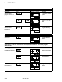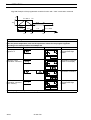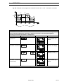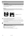
1
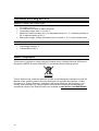
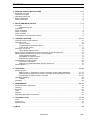
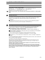
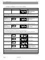
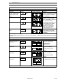
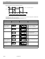
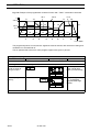
GB
Laboratory Air Circulation Ovens
Models UT 6 P, UT 12 P, UT 20 P
USA
Operating instructions
Valid: 09.2005 / 50042750 D
Below is a list of the international Thermo marketing organizations.
Postal address Germany
Thermo Electron LED GmbH
D – 63505 Langenselbold
Robert-Bosch-Strasse 1
Enquiries from Germany
Phone
Sales
0800 1 536376
Service
0800 1 112110
Fax
Sales/Service 0800 1 112114
E-Mail
[email protected]
Enquiries from Europe, Middle East
and Africa
Phone + 49(0) 6184 / 90-6940
Fax
+ 49(0) 6184 / 90-7474
E-Mail
[email protected]
Postal address USA
Thermo Electron Corporation.
275 Aiken Road
Asheville, NC 28804
USA
Enquiries from North America
Phone + 1 800-879 7767
Fax
+ 1 828-658 0363
E-Mail
[email protected]
Enquiries from Latin America
Phone + 1 828-658 2711
Fax
+ 1 828-645 9466
E-Mail
[email protected]
Enquiries from Asia Pacific
Phone + 1 852-2711 3910
Fax
+ 1 852-2711 3858
E-Mail
[email protected]
Internet: www.thermo.com
1a
Thermo Electron LED GmbH, 63505 Langenselbold, Germany
function line® is a registered trademark of Thermo Electron LED GmbH.
If translated versions of this manual are used, the German version is the authoritative basis.
Subject to technical modifications.
This instruction manual applies for the following models:
Order No.
Model
Equipment
50 042 298
UT 6 P
Air circulation oven, programmed controller, 1/PE AC, 230 V; 50/60 Hz
50 042 300
UT 6 P
Air circulation oven, programmed controller, 1/PE AC, 120 V; 50/60 Hz
50 042 306
UT 12 P
Air circulation oven, programmed controller, 1/PE AC, 230 V; 50/60 Hz
50 043 411
UT 12 P
Air circulation oven, programmed controller, 1/PE AC, 208 V; 50/60 Hz
50 042 312
UT 20 P
Air circulation oven, programmed controller, 1/PE AC, 230 V; 50/60 Hz
50 043 413
UT 20 P
Air circulation oven, programmed controller, 1/PE AC, 208 V; 50/60 Hz
The safety concerning the protection of persons, environment and material to be treated
mainly depends on the behavior of the operating personnel of these units.
Please read and observe the following instructions carefully before starting the unit in
order to avoid faults and resulting damage, especially adverse health effects.
2a
Information according EN 61010
AMBIENT OPERATING CONDITIONS
•
•
•
•
•
For indoor use only
For altitudes up to 2000 m above sea level
Temperature range from 5 °C to 40 °C
Maximum relative humidity: 80 %, for temperatures up to 31 °C, decreasing linearly to
50 % relative humidity at 40 °C
Main power supply: Voltage fluctuations not to exceed +/- 10 % of the nominal value
ELECTRICAL DATA
•
•
Overvoltage category: II
Contamination level: 2
WEEE Compliance:
This product is required to comply with the European Union`s Waste Electrical & Electronic
Equipment (WEEE) Directive 2002/96/EC. It is marked with the following symbol:
Thermo Electron has contracted with one or more recycling/disposal companies in each EU
Member State, and this product should be disposed of or recycled through them. Further
information on Thermo Electron`s compliance with these Directives, the recyclers in your
country, and information on Thermo Electron products wich may assist the detection of
substances subject to the RoHS Directive are available at www.thermo.com/WEEERoHS.
1a
CONTENTS
1. GENERAL SAFETY INSTRUCTIONS . . . . . . . . . . . . . . . . . . . . . . . . . . . . . . . . . . . . . . . . . . . . . . . . . . . . 4 - 6
Explanation of icons . . . . . . . . . . . . . . . . . . . . . . . . . . . . . . . . . . . . . . . . . . . . . . . . . . . . . . . . . . . . . . . . . . . . . . . . . . . . 4
General information . . . . . . . . . . . . . . . . . . . . . . . . . . . . . . . . . . . . . . . . . . . . . . . . . . . . . . . . . . . . . . . . . . . . . . . . . . . . 5
Operating instructions . . . . . . . . . . . . . . . . . . . . . . . . . . . . . . . . . . . . . . . . . . . . . . . . . . . . . . . . . . . . . . . . . . . . . . . . . . 5
Field of application . . . . . . . . . . . . . . . . . . . . . . . . . . . . . . . . . . . . . . . . . . . . . . . . . . . . . . . . . . . . . . . . . . . . . . . . . . . . . 5
Safety instructions . . . . . . . . . . . . . . . . . . . . . . . . . . . . . . . . . . . . . . . . . . . . . . . . . . . . . . . . . . . . . . . . . . . . . . . . . . . . . . 6
2. SETUP AND INSTALLATION . . . . . . . . . . . . . . . . . . . . . . . . . . . . . . . . . . . . . . . . . . . . . . . . . . . . . . . . . . . . 7 - 9
Transport . . . . . . . . . . . . . . . . . . . . . . . . . . . . . . . . . . . . . . . . . . . . . . . . . . . . . . . . . . . . . . . . . . . . . . . . . . . . . . . . . . . . . 7
Unpacking the unit . . . . . . . . . . . . . . . . . . . . . . . . . . . . . . . . . . . . . . . . . . . . . . . . . . . . . . . . . . . . . . . . . . . . . . . . 7
Installation . . . . . . . . . . . . . . . . . . . . . . . . . . . . . . . . . . . . . . . . . . . . . . . . . . . . . . . . . . . . . . . . . . . . . . . . . . . . . . . . . . . . . 7
Room ventilation . . . . . . . . . . . . . . . . . . . . . . . . . . . . . . . . . . . . . . . . . . . . . . . . . . . . . . . . . . . . . . . . . . . . . . . . . . . . . . . 8
Mains connection . . . . . . . . . . . . . . . . . . . . . . . . . . . . . . . . . . . . . . . . . . . . . . . . . . . . . . . . . . . . . . . . . . . . . . . . . . . . . . . 8
Noise insulation . . . . . . . . . . . . . . . . . . . . . . . . . . . . . . . . . . . . . . . . . . . . . . . . . . . . . . . . . . . . . . . . . . . . . . . . . . . . . . . . 8
Connecting to an air extraction system . . . . . . . . . . . . . . . . . . . . . . . . . . . . . . . . . . . . . . . . . . . . . . . . . . . . . . . . . . 9
3. UNIT SPECIFICATION . . . . . . . . . . . . . . . . . . . . . . . . . . . . . . . . . . . . . . . . . . . . . . . . . . . . . . . . . . . . . . . 10 - 17
Overview of the control elements . . . . . . . . . . . . . . . . . . . . . . . . . . . . . . . . . . . . . . . . . . . . . . . . . . . . . . . . . . . . . . 10
Switchgear unit . . . . . . . . . . . . . . . . . . . . . . . . . . . . . . . . . . . . . . . . . . . . . . . . . . . . . . . . . . . . . . . . . . . . . . . . . . . . . . . . 10
On / Off switch . . . . . . . . . . . . . . . . . . . . . . . . . . . . . . . . . . . . . . . . . . . . . . . . . . . . . . . . . . . . . . . . . . . . . . . . . . 10
Overtemperature protection device . . . . . . . . . . . . . . . . . . . . . . . . . . . . . . . . . . . . . . . . . . . . . . . . . . 10 - 11
Fresh-air flap control . . . . . . . . . . . . . . . . . . . . . . . . . . . . . . . . . . . . . . . . . . . . . . . . . . . . . . . . . . . . . . . . . . . . . 11
Automatic control unit . . . . . . . . . . . . . . . . . . . . . . . . . . . . . . . . . . . . . . . . . . . . . . . . . . . . . . . . . . . . . . . . . . . . . . . . . 12
Signal lamps, status function . . . . . . . . . . . . . . . . . . . . . . . . . . . . . . . . . . . . . . . . . . . . . . . . . . . . . . . . . . . . . 12
Basic functions: temperature control, time switch, air speed adjustment . . . . . . . . . . . . . . . . . . . . . . . . . 12
Added-feature programming functions, fixed programs . . . . . . . . . . . . . . . . . . . . . . . . . . . . . . . . . . . . . . . . . . 13
Fixed program segments . . . . . . . . . . . . . . . . . . . . . . . . . . . . . . . . . . . . . . . . . . . . . . . . . . . . . . . . . . . . . . . . . 14
Compilation of a fixed program . . . . . . . . . . . . . . . . . . . . . . . . . . . . . . . . . . . . . . . . . . . . . . . . . . . . . . . . . . . 14
Example of a fixed program . . . . . . . . . . . . . . . . . . . . . . . . . . . . . . . . . . . . . . . . . . . . . . . . . . . . . . . . . . . . . . 15
Programmed controller function . . . . . . . . . . . . . . . . . . . . . . . . . . . . . . . . . . . . . . . . . . . . . . . . . . . . . . . . . . . . . . . . 16
Termination commands . . . . . . . . . . . . . . . . . . . . . . . . . . . . . . . . . . . . . . . . . . . . . . . . . . . . . . . . . . . . . . . . . . 16
Example of a temperature/time program, definitions . . . . . . . . . . . . . . . . . . . . . . . . . . . . . . . . . . . . . . 16
What happens if ... ? . . . . . . . . . . . . . . . . . . . . . . . . . . . . . . . . . . . . . . . . . . . . . . . . . . . . . . . . . . . . . . . . . . . . . . . . . . 17
4. OPERATION . . . . . . . . . . . . . . . . . . . . . . . . . . . . . . . . . . . . . . . . . . . . . . . . . . . . . . . . . . . . . . . . . . . . . . . . 18 - 28
Starting up with
Basic functions - temperature control, time switch, blower speed adjustment . . . . . . . . . . 18 - 19
Added-feature programming functions, example hot-air sterilization prozess . . . . . . . . . . 20 - 21
Programmed controller functions, example . . . . . . . . . . . . . . . . . . . . . . . . . . . . . . . . . . . . . . . . . . 22 - 27
Operating guidelines . . . . . . . . . . . . . . . . . . . . . . . . . . . . . . . . . . . . . . . . . . . . . . . . . . . . . . . . . . . . . . . . . . . . . . . . . . . 28
Loading . . . . . . . . . . . . . . . . . . . . . . . . . . . . . . . . . . . . . . . . . . . . . . . . . . . . . . . . . . . . . . . . . . . . . . . . . . . . . . . . . 28
Shutdown . . . . . . . . . . . . . . . . . . . . . . . . . . . . . . . . . . . . . . . . . . . . . . . . . . . . . . . . . . . . . . . . . . . . . . . . . . . . . . . . . . . . 28
5. MAINTENANCE . . . . . . . . . . . . . . . . . . . . . . . . . . . . . . . . . . . . . . . . . . . . . . . . . . . . . . . . . . . . . . . . . . . . . . 29 - 30
Decontamination / disinfection . . . . . . . . . . . . . . . . . . . . . . . . . . . . . . . . . . . . . . . . . . . . . . . . . . . . . . . . . . . . . . . . . 29
Cleaning
. . . . . . . . . . . . . . . . . . . . . . . . . . . . . . . . . . . . . . . . . . . . . . . . . . . . . . . . . . . . . . . . . . . . . . . . . . . . . . . . . . . . 29
Servicing . . . . . . . . . . . . . . . . . . . . . . . . . . . . . . . . . . . . . . . . . . . . . . . . . . . . . . . . . . . . . . . . . . . . . . . . . . . . . . . . . . . . 30
Tests
. . . . . . . . . . . . . . . . . . . . . . . . . . . . . . . . . . . . . . . . . . . . . . . . . . . . . . . . . . . . . . . . . . . . . . . . . . . . . . . . . . . . 30
Repairs
. . . . . . . . . . . . . . . . . . . . . . . . . . . . . . . . . . . . . . . . . . . . . . . . . . . . . . . . . . . . . . . . . . . . . . . . . . . . . . . . . . . . 30
Approved spare parts / accessories . . . . . . . . . . . . . . . . . . . . . . . . . . . . . . . . . . . . . . . . . . . . . . . . . . . . . . . . . . . . 30
6. TECHNICAL DATA . . . . . . . . . . . . . . . . . . . . . . . . . . . . . . . . . . . . . . . . . . . . . . . . . . . . . . . . . . . . . . . . . . . 31 - 34
Oven
. . . . . . . . . . . . . . . . . . . . . . . . . . . . . . . . . . . . . . . . . . . . . . . . . . . . . . . . . . . . . . . . . . . . . . . . . . . . . . . 31 - 33
Control unit . . . . . . . . . . . . . . . . . . . . . . . . . . . . . . . . . . . . . . . . . . . . . . . . . . . . . . . . . . . . . . . . . . . . . . . . . . . . . . . . . . . . 34
Materials used . . . . . . . . . . . . . . . . . . . . . . . . . . . . . . . . . . . . . . . . . . . . . . . . . . . . . . . . . . . . . . . . . . . . . . . . . . . . . . . . 34
Log-Book
. . . . . . . . . . . . . . . . . . . . . . . . . . . . . . . . . . . . . . . . . . . . . . . . . . . . . . . . . . . . . . . . . . . . . . . . . . . . . . . . 35
50 042 750
3/ 35
1
GENERAL SAFETY INSTRUCTIONS
EXPLANATION OF ICONS
This symbol marks chapters and sections of this instruction manual which are particularly
relevant to safety.
When attached to the unit, this symbol draws attention to the relevant section of the
instruction manual.
Marks information about optimum utilization of the unit in the instruction manual.
Warns of hot surfaces.
set
Key for temperature selection, time-switch function and to confirm entered information
prog
Key for the programming function, time selection and to confirm entered information
vent
Key to set the air speed and to confirm entered information
Value adjustment key, INCREASE VALUE
Value adjustment key, REDUCE VALUE
Information about proper disposal / recycling
Overtemperature protection device
Fresh-air flap control
Continuous adjustment from minimum to maximum values
Quick reference guide to operation
Select the status of the control unit (enabled / disabled)
Temperature control function, select temperature
Time-switch function, set the operating times
P
Programming function
Blower function
4/35
50 042 750
1
GENERAL SAFETY INSTRUCTIONS
General information
The unit fulfils the following safety standards:
DIN EN 61 010 - 1 / 03.´94, VDE 0411 Part 1 / 03.´94, E DIN VDE 0411 Part 111,
DIN 12 880 Part 1 / 11.´78 and DIN EN 60 335 - 1, VDE 0700 Part 1
DIN EN 55 011 Part 3, DIN VDE 0875 Part 11 / 07.´92
Always quote the data on the rating plate when requesting information or ordering spare
parts
Operating instructions
The operator must provide anybody working on or with this equipment with written instructions for
any operations to be performed. Such instructions must be easy to understand and must be
available in the language of the respective personnel (FRG: UVV VBG 1 § 7 (2)).
Log book
We recommend that a log book is kept, which records any tests and calibration operations
performed on the unit and any other work (repairs, modifications etc.).
Field of application
The unit has been designed as an item of laboratory equipment for technical applications.
Heat treatment of samples or materials with operating temperatures of between
room temperature + approx. 20°C and 250 °C,
e.g. for drying, ageing, analysis, fusing, burning in, oxidizing, reducing, preheating, etc.
Hot-air sterilization, sterilization by heating the article up to a temperature of at least 160 °C
(FRG: also refer to DIN 58 947).
Note: The sterilization temperature usually required in the field of medical laboratory work is 180 °C.
The unit has been designed for installation and operation in the following fields:
Laboratories, e.g. in the commercial or industrial sector, schools, universities, hospitals and
biology
The unit is equipped with an independent overtemperature protection device, which means that it
does not require constant supervision.
The heating unit has been designed for continuous use.
Make sure that an adequate clearance is maintained between the inside walls of the inner
compartment and the loaded articles, and between the various layers of loaded articles, to
prevent uneven heating of the materials.
Protective gloves, goggles etc. must be made available to the operator because of the
potentially high operating temperatures.
The unit must not be used to dry or heat substances which may release combustible
gases or vapours into the atmosphere, which could burn or explode when mixed with air.
The heating unit is equally unsuitable for the heat treatment of combustible dusts or
fibrous materials.
50 042 750
5/ 35
1
GENERAL SAFETY INSTRUCTIONS
Safety instructions
Comply with the instructions in this manual and keep it in the vicinity of the unit.
These units must be operated in accordance with the instruction manual and may only be used
for their intended applications in order to ensure the safety of personnel, the environment and the
processed items and materials.
Read the instruction manual carefully and comply with the instructions that it contains to avoid
making mistakes and to prevent any peronal injury or damage to property.
Unit must be operated by instructed personnel.
Keep unit out of reach of children.
Apart from the instructions in this manual, the respective national regulations must also be
observed for the installation and operation of this unit (FRG: ZH 1/119, DIN 12 880 Part 1).
The applicable national environmental regulations must be observed for the extraction of exhaust
gases that are produced during heat treatment. Suitable measures must be implemented to
ensure that such gases are safely led outside (FRG: BImSchG, UVPG, AbfG, WHG, ChemG, ...).
The unit must not be used to dry or heat substances which may release combustible gases or
vapours into the atmosphere, which could burn or explode when mixed with air. The unit is
equally unsuitable for the heat treatment of combustible dusts or fibrous materials.
Check the mains lead and connector for damage before using the unit. If there are any signs of
damage, do not connect the unit up to the mains.
The voltage quoted on the rating plate (rated voltage) must agree with the mains supply voltage.
Protective gloves, goggles etc. must be made available to the operator because of the potentially
high operating temperatures.
The surfaces around the opening of the inner compartment become hot at high operating
temperatures - RISK OF BURNING - Avoid contact with these surfaces.
Ensure that the overtemperature protection device works properly by conducting a functional
check at regular intervals, every 3 months at least, and check the electrical equipment at least
once a year.
Any work to be conducted on the electrical equipment of the unit may only be performed by a
qualified electrician. The unit must be disconnected from the mains supply before commencing
service or repair work.
Only use approved accessories and approved genuine spare parts. The use of any other parts
may result in unforeseen problems and should be avoided under all circumstances.
The serviceability and safety of the unit can only be guaranteed if the necessary tests,
maintenance, servicing and repair work is carried out by the Thermo service personnel or other
agencies who are authorized to act on our behalf.
Thermo Electron LED GmbH cannot accept any liability for any damage that occurs as a
result of improper use or repair work, which has not been performed by Thermo service centers,
or if parts other than the approved genuine spare parts / accessories are used.
6/35
50 042 750
2
SETUP AND INSTALLATION
Transport
Handle the unit with care. Avoid jarring and protect against damage. Do not lift by the door
handle, the door itself, the control unit, the blower box, the spacer or the power lead.
Refer to the TECHNICAL DATA for dimensions and weight.
Unpacking the unit:
Unpack the unit, remove the transport safety fixtures from the inner compartment and remove
any dirt or dust which may have accumulated in transit.
Installation
The unit must be installed in a dry environment.
The relative humidity should be between 60 and 70 % under normal conditions.
Condensation should be avoided. If condensation has formed on the unit following a change of
location or during transporation, for example, wait until the unit has dried out completely before
putting into operation.
The ambient air should not contain excessive amounts of dust.
(Comply with the instructions in the MAINTENANCE section).
Do not cover or obstruct the ventilation or exhaust vents in the unit housing, remove any dust or
dirt with a vacuum cleaner.
The ambient temperature should not exceed 40 °C.
Place the unit on a firm, fireproof surface (e.g. laboratory table, support frame) in a stable,
perfectly upright position.
Keep the unit away from direct sunlight (UV radiation).
If you wish to stack two units on top of one another, use the stacking frame (available as an
option). Never stack more than two units on top of one another. When stacking units of different
types, make sure that e.g. an incubator is always at the bottom, and prevent any mutual
influence. Only units of the same size are stackable. In case of stacking two units inside a niche
the clearance to adjacent surfaces has to be increased on minimum one side to 200mm.
Fig. 1/2: Clearances to adjacent surfaces / objects:
Maintain a distance from the back:
UT 6 P:
at least 8 cm
UT 12 P: at least 8 cm
UT 20 P: at least 8 cm
30 cm
5 cm
5 cm
The wall spacer may only be removed if the
unit is connected up to an extraction system.
The exhaust gases must be led through / past
adjacent surfaces / objects located above or
behind the unit with heat insulation to avoid
the danger of fire.
If the unit UT 6 P is to be fitted under a table or into a laboratory fixture, it must be connected
to an exhaust air extraction system. The top clearance may only be reduced to min. 5 cm under
such circumstances. Ensure adequate ventilation.
Types UT 12 P and UT 20 P are not suitable to be fitted under a table.
50 042 750
7/ 35
2
SETUP AND INSTALLATION
Room ventilation
Adequate ventilation must be provided wherever the unit is installed.
Do not operate the unit in non-ventilated enclosed spaces.
Special ventilation measures (e.g. ventilation of designated work areas, FRG: also refer to VDI
1946 Part 7) when several units are installed in one room.
Mains connection
The laboratory unit is supplied with a permanently connected, flexible mains power lead with
connector (grounded).
The connector serves to disconnect the unit from the mains power supply.
Examine the power lead and connector for damage before using the unit. If there are any signs
of damage, do not connect the unit to the mains supply.
The voltage quoted on the rating plate (rated voltage) must agree with the nominal mains
voltage.
The unit may only be connected up to the mains via a properly installed socket outlet with PE
conductor (protection class I) or a permanent terminal connection.
In the event of a permanent terminal connection, a master switch (lockable in the "Off"
position) must also be installed to disconnect the unit from the mains.
An earth-leakage circuit-breaker should also be fitted in the supply system to provide
additional protection against electric shocks.
Rubber-sheathed flexible cable of at least 2.5 mm2 diameter (H 07 RN-F ...) should be used for
any extensions that may be required to connect the unit.
Refer to the TECHNICAL DATA section for the rated power consumption, circuit protection
with a T 16 A fusible link or a B 16 circuit-breaker.
Noise insulation
The unit develops a constant noise load.
Refer to the TECHNICAL DATA section for the noise level.
The unit may produce higher noise levels in unfavorable installation conditions. Supplementary
measures may have to be implemented to improve the sound insulation in the room.
8/35
50 042 750
2
SETUP AND INSTALLATION
Connecting to an extraction system
Comply with the applicable national environmental regulations for the extraction of
exhaust gases released during the heat treatment. Suitable measures must be
implemented to ensure that such gases are safely led outside (FRG: BImSchG). Such
measures may involve thermal or catalytic treatment of flue gases.
Refer to the TECHNICAL DATA section for the volume flow and temperature of the exhaust
gases.
Fig. 2/2: Example of an installation
3
2
1
5
4
6
1
2
3
4
5
6
Inlet air flow
Heating cabinet
Adjacent surface / object
Exhaust-air blower
Exhaust air flow
Draft breaker
Implementation instructions:
A draft breaker must be used to connect the unit to an extraction system.
All flue ducts must be made of fireproof materials.
Apertures must be provided to enable the removal of residue and condensate. The flue
ducts must be thermally insulated (recommendation: half-shell sleeves made of laminated
mineral fiber).
The exhaust air / gases from the unit must never come into contact with combustion exhaust gases.
Use the draft breaker to adjust the air flow volume in such a way that exhaust gases can be
extracted reliably without producing any eddying at the unit's exhaust-gas connector.
Technical measures should be implemented to monitor the flow of air and flue gases and to
prevent operation of the heating unit if the ventilation system is switched off / defective
(electrical interlock).
50 042 750
9/ 35
3.
UNIT SPECIFICATION
Fig. 1/3: Overview of the control elements
C
A
B
C
Switchgear unit
Automatic control unit
Door handle
2
1
2
3
3
4
On / Off switch
Overtemperature protection,
control element
"Fault" signal lamp
Fresh-air flap adjustment
B
A
Item A: Switchgear unit
Fig. 2/3: Switchgear unit control panel
1
on
4
off
1
ON / OFF switch:
To switch the unit on and off:
"on" =
Unit switched on, the temperature inside the unit appears on the display panel
of the control unit.
"off" =
Unit switched off, temperature display off.
2&3
Overtemperature protection device / signal lamp:
The unit is equipped with an electronic upper-limit cut-out device (TWB) of protection class 2
as defined by DIN 12 880 Part 1. It is electrically and functionally independent of the temperature
control system. In the event of a fault in the unit heating system, the operational TWB shuts
down the unit heating across all poles as soon as the temperature exceeds the preset value.
The red signal lamp indicates activation of the protection function (Fig. 2/3: Item 3).
The unit must be reset manually, by pressing the control element.
Allow the unit to cool down (by approx. 30 °C), press the control element, the red signal lamp
will go out.
The operate value is adjusted with the help of a tool (coin, screwdriver...).
Adjust to the required protection level:
to upper temperature limit = unit protection (protects the unit and its environment).
to approx. 10 °C higher than the operating temperature set on the control unit =
material protection (protects the unit, its environment and the loaded material).
Ensure that the overtemperature protection device works properly by conducting a
functional check at regular intervals, every 3 months at least, and check the electrical
equipment at least once a year.
10/35
50 042 750
3.
UNIT SPECIFICATION
2 & 3 Overtemperature protection device / signal lamp:
Functional test of the TWB
(Prerequisite: required working temperature (control unit) has been reached /remains constant)
Set the TWB to approx. 10 - 20 °C below the temperature displayed on the control unit. The
TWB must respond, the red signal lamp indicates "Fault".
The TWB is working properly. Press the control element to release the TWB.
Now set the TWB to the temperature limit for the required type of protection.
If "Fault" is signalled during operation:
Check the settings of the TWB and the control unit and correct if necessary. If set for "material
protection", this may indicate a blower malfunction. If the problem persists, contact the service
center.
4
Fresh-air flap control
For continuous control of the fresh-air supply to the inner compartment.
Set to left-hand stop
=
minimum fresh-air supply
Set to right-hand stop
=
maximum fresh-air supply
50 042 750
11/ 35
3.
UNIT SPECIFICATION
Item B:
Automatic control unit
The automatic control unit contains the basic functions of a 2-position controller with PD/PID
control response, time switch to switch the heating and ventilation on / off after the set time, the
added features of permanently programmed heating process programs and the programmed
controller functions of a freely programmable process controller.
Fig. 3/3: Control unit control panel
1
2
3
4
°C
5
1
2
3
4
5
6
7
8
9
set
prog
vent
9
8
7
Signal lamp - heating status
Signal lamp - control unit status
Display panel
Control key
"Increase displayed value" key
"Reduce displayed value" key
"Programming function" key
"Air speed adjustment" key
Display panel
6
The status of the control unit is indicated by signal lamps in the display panel.
THE YELLOW SIGNAL LAMP (Item 1) indicates the current status of the heating control system:
Lamp switched on = unit heating activated
Lamp switched off = heating off
Rhythmic flashing of this signal lamp indicates that the temperature controller is regulating
the operating temperature.
THE GREEN SIGNAL LAMP (Item 2) indicates the status of the control unit:
Lamp on
= control unit switched on: heating and blower enabled.
The heating and blower are activated when the unit is switched on (On / Off switch).
Lamp off
= control unit switched off: heating and blower disabled.
The heating and blower are not activated when the unit is switched on.
Lamp flashes =
time-switch function activated.
Basic functions
The control unit is equipped with the "temperature control", "time switch" and "inside air
speed adjustment" basic functions.
The unit can set an operating temperature of up to 250 °C, switching times of between
0:01 and 99:00 hours and and inside air speed in stages of approx. 40 %, approx. 70 % and
100 %.
Refer to STARTING UP WITH BASIC FUNCTIONS for information about the commands for
the basic functions.
12/35
50 042 750
3.
UNIT SPECIFICATION
Added-feature programming functions, fixed programs
The control unit is capable of running heating process programs with fixed, preselected
parameters from a database.
The program segment and the parameters are stored in the database.
The fixed program contains a maximum of four program segments and a status command.
Only one fixed program can be stored. In the programmed controller function one arbitrary
difined program can be stored independend of the fixed program.
Fig. 4/3: Example of a temperature/time process, controlled by the fixed program
P I
P 2
P 3
P 5
P 4
T (°C)
T
T
t hold
t on
P I. 0 - P I. 9
1 h
1 h
P 2. 0 - P 2. 9
P 3. 0 - P 3. 9
P 4. 0 - P 4. 9
t (h)
P. o F
P. o n
P. r E
Each program segment, P I - P 4, is assigned to a typical temperature / time response. 10
selectable sets of parameters are permanently stored in the database for each program
segment. These sets of parameters can be assigned within the program.
A status command is provided as the fifth program segment. This determines the subsequent
action with the program selected from the fixed program memory:
Program on standby, do not execute yet
= Select " P. o F "
Program on standby, wait for program start
= Select " P. o n "
Delete program from memory completely
= Select " P. r E "
The program memory is erased on delivery. If the operator interrogates the program segments,
"Parameter set off" appears in the display panel = e.g. " P. I - ".
When compiling a program, selecting "parameter set off" within the selected program segment
causes the control unit to bypass this segment for the fixed program function.
The selected program always runs from program segment P I. n to program segment P 4. n.
If program segment P 3. n is combined with program segment P 4. n, the heating and blower are
only switched off following termination of segment P 4. n.
If a program is interrupted and started again, the sequence commences at segment P I. n.
The previously selected operating temperature cannot be changed once the program has
started.
The heating is switched off in the event of a power failure (> 20 ms) with subsequent restoration
of the power supply, the temperature inside the unit is displayed as a flashing value and the
program must be started again.
50 042 750
13/ 35
3.
UNIT SPECIFICATION
Fixed program segments:
Program segment " P 1. n " (n = -, 0 ... 9):
Assigning a parameter ( 0 ... 9 ) from the database causes the unit to switch on heating and ventilation
on expiry of a preset period.
Selectable parameters in this program segment:
P I. -
P I. 0
P I. I
P I. 2
P I. 3
P I. 4
P I. 5
P I. 6
P I. 7
P I. 8
P I. 9
off
2h
4h
6h
8h
10 h
12 h
16 h
20 h
24 h
72 h
Program segment " P 2. n " (n = -, 0 ... 9):
Assigning a parameter ( 0 ... 9 ) causes the unit to heat up to the preset operating temperature at a
specific rate of temperature change per hour.1)
Selectable parameters in this program segment:
P 2. -
P 2. 0
P 2. I
P 2. 2
P 2. 3
P 2. 4
P 2. 5
P 2. 6
off
10°C/h
20°C/h
30°C/h
40°C/h
50°C/h
60°C/h
80°C/h 100°C/h 120°C/h 200°C/h
P 2. 7
P 2. 8
P 2. 9
Program segment " P 3. n " (n = -, 0 ... 9):
Assigning a parameter ( 0 ... 9 ) causes the unit to heat up to the preset operating temperature, to
maintain this temperature for the preset period and to subsequently switch off heating and
ventilation
Selectable parameters in this program segment:
P 3. off
P 3. 0
P 3. I
P 3. 2
P 3. 3
P 3. 4
P 3. 5
P 3. 6
P 3. 7
P 3. 8
P 3. 9
1h
1.5 h
2h
4h
6h
8h
12 h
24 h
15 min. 30 min.
Program segment " P 4. n " (n = -, 0 ... 9):
Assigning a parameter ( 0 ... 9 ) causes the unit to cool down from the previously reached inside
temperature at a specific rate of temperature change and to subsequently switch off heating and
ventilation.1)
Selectable parameters in this program segment:
P 4. off
P 4. 0
P 4. I
P 4. 2
P 4. 3
P 4. 4
P 4. 5
P 4. 6
P 4. 7
P 4. 8
P 4. 9
1°C/h
2°C/h
5°C/h
10°C/h
20°C/h
30°C/h
40°C/h
50°C/h
60°C/h
80°C/h
1) according to model and load
Compilation of a fixed program
After activating the added-feature function, the sequence is compiled by marking the required
program segments.
Example: Fixed program comprising P I. 2; P 2. -; P 3. 7; P 4. 4 and P. o n :
P I.-
P I . 4 P I. 5 P I . 6
10 h
12 h
16 h
P I. 7
P I. 8
P I. 9
20 h
24 h
72 h
P 2. 0 P 2. I P 2. 2 P 2. 3 P 2. 4 P 2. 5 P 2. 6
P 2. 7
P 2. 8
P 2. 9
P I. 0
2 h
P 2.-
P I. I
P I. 2
P I. 3
4 h
6 h
8 h
10°C/h 20°C/h 30°C/h 40°C/h 50°C/h 60°C/h 80°C/h 100°C/h 120°C/h 200°C/h
P 3.-
P 3. 0 P 3. I P 3. 2 P 3. 3 P 3. 4 P 3. 5 P 3. 6 P 3. 7
1/4 h
P 4.-
P.o F
14/35
1/2 h
1 h
1,5 h
2 h
4 h
6 h
P 4. 0 P 4. I P 4. 2 P 4. 3 P 4. 4 P 4. 5 P 4. 6
1°C/h
2°C/h
P.o n
P.r E
8 h
P 3. 8
P 3. 9
12 h
24 h
P 4. 7
P 4. 8
P 4. 9
5°C/h 10°C/h 20°C/h 30°C/h 40°C/h 50°C/h
60°C/h
80°C/h
50 042 750
3.
UNIT SPECIFICATION
Example of a fixed program
Example E1: Hot-air sterilization process
The heating should switch on in 8 hours, the unit should heat up to an operating temperature of
190 °C (sterilization temperature) at a rate of 200 °C/h, maintain this temperature for 4 hours
(equalization phase and sterilization period) and should subsequently cool down at a rate of 20
°C/h.
The program should start following program selection (status command: P. on).
Fig. 5/3: Program profile - hot-air sterilization process E1
T
S 1
S 2
S 3
S 4
S 1 - S 4 = Programmsegment
190 °C
t
P I. 3
P 2. 9
P 3. 5
P 4. -
P. o n
Sequence E1:
After sketching the process characteristic, select the segments which correspond to the
required sequence from the matrix .
Mark the program segments and the " P. o n " status command. Leave program input mode.
Select 190 °C as the required operating temperature. Start the fixed program.
While the program is running the display alternates between the temperature inside the unit
and the current program segment.
Refer to STARTING UP WITH ADDED-FEATURE PROGRAMMING FUNCTIONS for further
information.
50 042 750
15/ 35
4
OPERATION
Programmed controller function
The programmed controller function enables the arbitrary definition of temperature / time
processes.
You may select up to 9 program segments. Operating temperature, period and air speed level
can be selected for each segment.
Termination commands
A termination command can be selected as the last program segment beginning at the second
segment. The termination command determines the function to be performed by the unit after
running through the program.
There are three optional termination commands:
" hold " =
Once the program has terminated, the operating temperature set for the last
program segment is maintaned until a new operating temperature has been
selected.
" StOP " =
Once the program has terminated, the heating and blower are switched off
until the "stop" command is cancelled.
" CYCL " =
Once the program has terminated, it returns to the beginning and is repeated
continuously until the "CYCL" command is cancelled.
A termination command must always be entered at the end of every program.
Fig. 6/3: Example of a temperature / time / ventilation program with "CYCL" termination
command
U/T
40 %
T1
70 %
100 %
T2
Un
Tn
T3
n1
n2
t1
n3
t2
T4
n4
t3
T7
T5
n5
t4
T6
n6
t5
T8
T9
n7
t6
n8
t7
n9
t8
t9
t
n 10 = CYCL
Definitions
n 1 ... n 9
n 10
T 1 ... T 9
t 1 ... t 9
U 1 ... U 3
Program segments
Termination commands (hold, StOP or CYCL)
Specified operating temperature (50 - 250 °C)
Specified time - program segment (0:01 - 99:0 h)
Specified ventilation level (approx. 40 %, approx. 70 % and 100 %)
After a power failure >20ms up to approx. 2h the program will be continued at the last
temperature/time-values.
Refer to STARTING UP WITH PROGRAMMED CONTROLLER FUNCTIONS for details.
16/35
50 042 750
4
OPERATION
What happens if ... ?
Possible display
Explanation
888
Control unit test phase
oFF
Status of the control unit, heating and ventilation disabled, possibly
time-switch-funktion has been aktivated
signal lamp - control unit status
flashes
time-switch function activated
One digit in the display flashes
The flashing value can be changed
P 1.3
Program segment when entering an added-feature program function
P 1.3 alternating with inside
temperature
Program segment while the added-feature program is in progress
P. o n
Status command for an added-feature program:
Program on standby, wait for program start
P. o F
Status command for an added-feature program:
Program on standby, do not execute yet
P. r E
Status command for an added-feature program:
Delete program from memory completely
P r o alternating with inside
temperature
Entered program on standby
Power failure (> 20 ms) with subsequent restoration: the heating
switches off, "P r o" alternates with the temperature inside the unit
on the display, if a program is in progress it is interrupted and must
be started again.
n I
Program segment when entering and activating the programmed
controller function.
hold
Termination command when entering the programmed controller
function: the temperature set for the last program segment is
maintained on termination of the program
StOP
Termination command when entering the programmed controller
function: the heating and ventilation is switched off on termination of
the program
CYCL
Termination command when entering the programmed controller
function: when the program is terminated, it returns to the beginning
and starts again
---
A termination command is entered for this program segment when
entering the programmed controller function. The termination
command must be changed to a time value to enable the input of a
temperature value.
E-3
Stored data defective
Switch the unit off and on again. If the problem persists, contact the
service center
E-4
Error of measurement in the reference values
- contact the service center -
E-5
Upper-limit violation of actual temperature tolerance
- contact the service center -
E-6
Lower-limit violation of actual temperature tolerance
- contact the service center -
E-7
Temperature sensor or input defective - contact the service center -
E-8
Stored data defective
- contact the service center -
E-9
Erroneous reference values
- contact the service center -
50 042 750
17/ 35
4
OPERATION
After setup and installation, proceed as follows to start up:
Starting up with basic functions, without programming
Instruction
Key(s)
Example of display
Switch unit on
On / Off switch = "on"
Remarks
The green status display
indicates the status.
Display panel: inside
temperature
The unit runs through a self-test phase after switching on, display: " 888 ".
If the "off" status was selected for the previous operating phase, the display alternates between the
temperature inside the cabinet and the "oFF" status.
Selecting the control unit status function
approx. 3
sec.
Control unit "on":
(heating and
ventilation enabled)
Inside temperature, green
signal lamp lights up
continuously
Select this status function
to operate the unit, or
to use the time-switch function to switch the heating and ventilation off after a preset period
Control unit "off":
(heating and
ventilation disabled)
approx. 3
sec.
Inside temperaturealternating
with "off", green signal lamp
remains dark
Select this status function
to switch the heating and ventilation off, or
if the heating and ventilation is to remain off during programming, or
to use the time-switch function to switch the heating and ventilation on after a preset period
Setting the operating temperature
Display the preset
operating temperature
Preset operating temperature
set
Display flashes
Increase the preset
operating temperature
Value increases
Display flashes
Reduce the preset
operating temperature
Value decreases
Display flashes
Store new preset
operating temperature
New operating temperature
is stored, then inside
temperature appears on
display
set
Unit regulates the operating temperature when status "on", yellow signal lamp indicates the status of
the heating control system.
Adjusting the overtemperature protection device: refer to Chapter 3
Setting the position of the fresh-air flap
>>>
18/35
50 042 750
4
OPERATION
>>>
Setting the switching time
Instruction
Select time-switch
function, display time
remaining for timing
period
Key(s)
set
Example of display
approx. 3
sec.
Remarks
Display flashes, time-switch
funcition is displayed. If timing
period in progress, displays
time remaining
Increase preset time
Value can be adjusted
between 1 minute and 99
hours. Adjustable in full hours
from 10.0 hour setting.
Reduce preset time
The heating is switched on or
off, according to set status,
once timing period has
expired, e.g. control unit
status "off" - time-switchfunction switches "on".
Store new preset time
value
The time value is transferred
to the memory, the inside
temperature then appears on
the display.
set
The flashing status display indicates that the time-switch function has been activated. In this case
the status of the control unit "on " or "off" can´t be changed, if desired the switching time has to be set
to "0.00".
If you do not wish to use the time-switch function, enter 0. 0 0 as the preset time.
Selecting the air speed level
Display the preset air
speed level
Preset air speed level
vent
Display flashes,
speed symbol
Increase preset air
speed level
Value increases
(e.g. 70 % / 100 %)
Display flashes, speed
symbol
Value decreases
(e.g. 70 % / 40 %)
Reduce preset air
speed level
Display flashes, speed
symbol
Store new preset air
speed level
Air speed level is stored and
the display then goes dark
vent
Note: With air speed level lower than 100% a swelling noise is generated by the ventilator.
50 042 750
19/ 35
4
OPERATION
Fig. 1/4: Example of a hot-air sterilization process
T
S 1
S 2
S 3
S 4
S 1 - S 4 = Programmsegment
190 °C
t
P I. 3
P 2. 9
P 3. 5
P 4. -
P. o n
The heating is to switch on in 8 hours, the unit should heat up to 190 °C at 200 °C/h, maintain this
temperature for 4 hours, then switch off.
The program should start following program selection (P. o n).
Starting up with added-feature programming functions
Instruction
Key(s)
Example of display
Remarks
Switch unit on, select operating temperature: refer to start-up with basic functions
Adjusting the overtemperature protection device: refer to Chapter 3
Control unit "off", unit
should not heat up
during this input
Call fixed program
memory
Select parameter PI. 3
set
approx. 3
sec.
Status display = "oFF",
control unit is disabled, inside
temperature is displayed
approx. 6
sec.
Display flashes, program
segment S1 appears after 6
sec.
Programmable digit flashes.
P I. is displayed if no
parameter has been marked
set
Programmable digit flashes
Mark P I. 3 as the
required parameter in
program segment S1
P I. 3 is transferred to the
memory, programmable digit
flashes
set
Select program
segment S2
Programmable digit flashes
Continue in the same manner to enter / mark program segments P 2. 9, P 3. 5 und P 4.
>>>
20/35
50 042 750
4
OPERATION
>>>
Entering the status command
Instruction
Key(s)
Example of display
P. o F is displayed
Call status command
Select status command
Remarks
P. o F flashes
set
P. o n flashes
Mark status command
P. o n is displayed
set
Display alternates between
inside temperature and
"Pro"
Leave program
memory
Input terminated
Starting the added-feature program
Start the program
approx. 3
sec.
Program is started, the
display alternates between
the temperature and the
program segment
Terminating the added-feature program
Terminate the program
approx. 3
sec.
50 042 750
Display alternates between
the inside temperature and
"Pro"
21/ 35
4
OPERATION
Fig. 2/4: Example of the programmed controller function with " StOP " termination command
40 %
T
T1
100 %
70 %
T2
T7
T8
230 °C
T3
T4
T5
T6
T9
150 °C
70 °C
n1
n2
t1
n3
t2
n4
t3
n5
t4
n6
t5
n7
t6
n9
n8
t7
t8
t9
t
n 10 = StOP
The program sequence from a total of 9 segments must be entered, after which the heating and
ventilation is to be switched off.
The air speed levels to be set for each program segment are given in percent.
Starting up with programmed controller functions
Instruction
Key(s)
Example of display
Remarks
Switch the unit on, refer to start-up with basic functions
Adjusting the overtemperature protection device: refer to Chapter 3
Control unit "off", unit
should not heat up
during this input
Call main program
memory
ca. 3 Sek.
&
prog
Inside temperature,
green signal lamp
lights up continuously
Program segment
"n I" is displayed,
programmable digit
flashes
>>>
22/35
50 042 750
4
OPERATION
>>>
Entering the time for a program segment
Instruction
Enter the time for
program segment n I,
2:00 h
Key (s)
Example of display
The time for n I
flashes in the display
prog
or
Transfer the preset
time for program
segment n I to the
memory
Remarks
Time t 1= 2 . 00
n I is displayed,
programmable digit
flashes
prog
>>>
Entering the temperature for a program segment
Enter operating
temperature T 1,
230 °C
Preset operating
temperature for
program segment
1(n I) flashes in
display
set
If " - - - " appears in the display when the set key is pressed, then "hold" or "StOP" has been entered as
the termination command for program segment n I. If you wish to enter a temperature value, you must
first change the termination command to a time value (refer to the section on "Entering the time for a
program segment").
or
Transfer temperature
T1=230 °C to the
memory
Enter 230 °C
Program segment
" n I " is displayed,
programmable digit
flashes
set
50 042 750
23/ 35
4
OPERATION
>>>
Entering the air speed level for a program segment
Instruction
Select the preset air
speed level for
program segment n I
Key(s)
Example of display
Air speed level flashes
in the display, speed
symbol
vent
or
Transfer the preset air
speed level for
program segment n I to
the memory
Remarks
Select air speed level,
approx. 40 % in this
case
n I is displayed,
programmable digit
flashes
vent
Selecting the next program segment
Select program
segment n 2
n 2 is displayed,
programmable digit
flashes
Enter the preset operating temperatures, time values and air speed levels for program
segments n 2 - n 9 in the same manner as for program segment n 1 and select program
segment n 10.
Selecting the termination command
Select the "StOP"
termination command
Termination command
flashes in the display
prog
Enter the "StOP"
termination command
Transfer the
termination command
to the memory
n 10 is displayed,
programmable digit
flashes
prog
>>>
24/35
50 042 750
4
OPERATION
>>>
Leaving the program memory
Instruction
Key (s)
Leave the program
memory
set
Display
&
Remarks
Inside temperature is
displayed
prog
Input terminated
Starting the program
Instruction
Key (s)
Start the program
prog
Example of display
approx. 6 sec.
Remarks
Inside temperature
and program segment
are displayed
Terminating the program
Instruction
Terminate the program
Key(s)
prog
Example of display
approx. 6 sec.
50 042 750
Remarks
Inside temperature
and control unit status
are displayed
25/ 35
4
OPERATION
Fig. 3/4: Example of the programmed controller function with " hold " termination command
T
T1
100 %
T2
70 %
Tn
T3
40 %
n1
n2
t1
n3
t2
n 4 = hold
t3
t
Starting up with programmed controller function
The "hold" termination command has been selected here as an alternative to example 2/4.
Enter the preset temperature, time and air speed level values for the program segments
according to the same procedure as example 2/4.
Instruction
Key(s)
Example of display
Select program
segment n 4
Select the "hold"
termination command
n 4 is displayed,
programmable digit
flashes
Termination command
flashes in the display
prog
or
Transfer the
termination command
to the memory
Enter the "hold"
termination command
n 4 is displayed,
programmable digit
flashes
prog
Leave the program memory and start the program
26/35
Remarks
50 042 750
4
OPERATION
Fig. 4/4: Example of the programmed controller function with " CYCL " termination command
T
T1
T2
100 %
70 %
Tn
T3
T4
40 %
40 %
n1
n2
t1
n3
t2
n4
t3
t4
t
n 5 = CYCL
Starting up with the programmed controller function
The "CYCL" termination command has been selected here as an alternative to example 2/4.
Enter the preset temperature, time and air speed level values for the program segments
according to the same procedure as example 2/4.
Instruction
Key(s)
Example of display
Select program
segment n 5
Select the "CYCL"
termination command
n 5 is displayed,
programmable digit
flashes
Termination command
flashes in the display
prog
or
Transfer the
termination command
to the memory
Remarks
Enter the "CYCL"
termination command
n 5 is displayed,
programmable digit
flashes
prog
Leave the program memory and start the program
50 042 750
27/ 35
4
OPERATION
Operating guidelines
Remember to put on protective garments, e.g. gloves, goggles, mask, body protection, remove
any items of jewellery before starting work.
Do not cover or obstruct the ventilation or exhaust vents in the unit housing. Always keep these
vents free of dust and dirt.
Loading:
Circulating air conducts the heat to the samples in the unit. Make sure that the samples are
evenly distributed on the trays, and that they are arranged in such a way as to ensure an
unimpeded flow of warm air throughout the cabinet, in order to prevent local overheating. Do not
position the samples too close to the inner walls.
Fig. 5/4: Loading diagram
a
a
"a" = approx. 1/10 of the internal
dimensions
a
a
Be careful not to damage the temperature sensors in the inner chamber when loading.
Never place samples on the floor of the chamber!
Keep the inner surfaces of the chamber free of dust and dirt. Never use aggressive chemicals
which could damage the stainless steel finish.
Continually heating and cooling the unit over wide temperature ranges can detrimentally affect its
service life. If used more frequently, it is better to keep the unit running in continuous mode at
moderate temperatures.
If not used for an extended period, disconnect the unit from the power supply.
Shutdown
Remove the samples from the chamber
Allow the heating unit to cool down to room temperature
Switch the unit off and disconnect from the mains
Clean the inside surfaces of the chamber
(also refer to the section on DECONTAMINATION, CLEANING ...)
28/35
50 042 750
4
OPERATION
The serviceability and safety of the heating unit can only be guaranteed if the necessary
tests, maintenance, servicing, and repair work is carried out by the Thermo service
personnel or other agencies who are authorized to act on behalf of Thermo Electron
LED GmbH.
Thermo Electron LED GmbH cannot accept any liability for any damage that occurs
as a result of improper use or repair work, which has not been performed by Thermo
service centers, or if parts other than the approved genuine spare parts / accessories are
used.
We recommend that you enter into a service contract with our company. Please contact us for a
quotation.
Decontamination / disinfection
The operator is responsible for implementing suitable, effective measures to
decontaminate the unit if it is used in connection with hazardous materials. Such
measures must be conducted on a regular basis under normal operating conditions and
in particular if such materials have been spilt or before commencing service work.
The stainless steel components inside the unit may be decontaminated by wiping out with a
disinfectant solution in cases of biological contamination.
A surface disinfectant recommended by Thermo can be ordered under part
number 50052425 (250 ml spray bottle) and 50051939 (500 ml refill bottle).
Details for efficiency and approvals are available on request.
The applicable national regulations must be observed with respect to disinfection (FRG:
ZH 1/598 ... )
Once removed, the internal stainless steel components may also be subjected to steam
sterilization or autoclave treatment.
Cleaning
Use a mild soap solution (water and mild detergent) and a soft lint-free cloth to wipe the outer
surfaces and control elements of the unit.
Remove any dust deposits from the air vents with a vacuum cleaner.
Remove any dust or dirt from the inner chamber. Use stainless steel cleaning agents in
moderate quantities. Never use acids, chloric solvents or salt solutions to clean the stainless
steel surfaces inside the unit.
Avoid scouring and scratching, or damage to labels and paintwork will be unavoidable.
Include flue/exhaust ducts in the cleaning operations if the unit is connected up to an extraction
system.
Consult the manufacturer before implementing any other cleaning or disinfection
measures than those mentioned in this manual to ensure that the intended methods will
not damage the unit.
50 042 750
29/ 35
5
MAINTENANCE
Servicing
The heating unit is virtually maintenance-free.
Lubricate the bearing s of the door and door-handle mechanisms with a little synthetic oil from
time to time.
Mineral oil products must not be used where they may come into contact with plastic
components, as they could cause damage to such parts.
Tests
The following items should be tested at least once a year to ensure that the unit remains
in good working order:
Mechanical functions
Operation in accordance with the specified technical data
Electrical system (FRG: UVV VBG 4, DIN VDE 0701 Part 1, E DIN VDE 0702 / 11.93)
Safety devices
Repairs
Only approved genuine spare parts and accessories may be used.
The use of other parts may result in unforeseen problems and should be avoided under
all circumstances.
Approved spare parts / accessories
Spare part /accessory
Kendro order number
Size / model
UT 6 P
UT 12 P
Instruction manual
50 043 079
Circuit diagram 1/PE AC, 230 V / 208 V
50 041 987
UT 20 P
Circuit diagram 1/PE AC, 120 V
50 040 640
-
-
Wire tray with supporting straps
50 042 916
50 042 917
50 042 918
Stainless Steel perforated shelf with supports
50 044 611
50 044 612
50 044 613
Seasoned silicone rubber door seal
50 042 499
50 042 484
50 042 351
Stacking frame
50 042 906
50 042 907
50 042 908
Support frame 780mm high
50 045 045
50 045 046
50 045 047
Support frame 300mm high
50 045 049 50 045 050
50 045 051
Foot
50 042 541
Clasp for the door latching mechanism
50 042 284
Other spare parts and accessories to order
30/35
50 042 750
6
TECHNICAL DATA
DATA
Model
UT 6 P
UT 12 P
UT 20 P
Unit
552 x 700 x 685
696 x 850 x 685
754 x 910 x 865 mm
408 x 459 x 334
552 x 610 x 334
610 x 672 x 514 mm
326 x 367 x 275
441 x 488 x 267
488 x 537 x 411 mm
MECHANICAL
Dimensions
(W x H x D)
Housing
Chamber
Useful space
1)
Minimum
clearances to
adjacent
surfaces /
objects
Left
50
mm
Right
50
mm
300 (50 when connected to an extraction system)
mm
Rear
120
80
80
mm
Volumes
Chamber
(empty)
64.4
112
210
liter
33
57.6
107.8
liter
Steam space
approx. 73
approx. 131
approx. 234
liter
Unit
approx. 40
approx. 55
approx. 75
kg
Lumped
15
15
10
kg
Surface
20
20
15
kg
Total
50
50
70
kg
2/9
2 / 14
2 / 16
362 x 333
506 x 323
564 x 503
Top
Useful space 1)
Weights
Trays
Max. tray load
Number
Standard / Max.
Dimensions
(W x D):
piece
mm
THERMAL
Operating temperatures
°C
Room temperature + 20 to 250
Temperature deviations, circulating mode, air flap closed
Spatial 1)
Temporal 1)
at 70 °C
+ 1,0
+ 1,0
+ 1,5
K
at 150 °C
+ 2,0
+ 2,0
+ 3,0
K
at 250 °C
+ 4,0
+ 4,0
+ 5,0
K
at 70 °C
+ 0,2
+ 0,2
+ 0,1
K
at 150 °C
+ 0,4
+ 0,4
+ 0,6
K
at 250 °C
+ 0,7
+ 0,8
+ 0,8
K
Temperature deviations, fresh-air mode, air flap open
Spatial 1)
Temporal
1)
at 70 °C
+ 1,0
+ 1,0
+ 1,5
K
at 150 °C
+ 3,0
+ 3,0
+ 3,0
K
at 250 °C
+ 6,0
+ 5,0
+ 6,0
K
at 70 °C
+ 0,2
+ 0,2
+ 0,2
K
at 150 °C
+ 0,4
+ 0,4
+ 0,7
K
at 250 °C
+ 1,0
+ 1,0
+ 1,5
K
Warm-up times, circulating mode (unit empty, air flap closed, to 98 % of the operating temperature)
Operating
temperature
70 °C
8
8
9
min
150 °C
19
12
20
min
250 °C
42
50
60
min
1) in accordance with DIN 12 880 Part 2 / 11.´78
50 042 750
31/ 35
6
TECHNICAL DATA
DATA
Model
UT 6 P
UT 12 P
UT 20 P
Unit
THERMAL
Warm-up-times, fresh-air mode (unit empty, air flap open, to 98 % of the operating temperature)
Operating
temperature
70 °C
10
10
10
min
150 °C
25
20
25
min
250 °C
55
40
55
min
Cool-down times, circulating mode (unit empty, air flap closed, to 50 °C)
Operating
temperature
250 °C
120
150
180
min
150 °C
90
120
140
min
70 °C
40
50
50
min
Recovery times (unit empty, door open 60 s, to 98 % of the operating temperature)
Operating
temperature
70 °C
2
2
2
min
150 °C
5
6
7
min
250 °C
9
8
11
min
Heat radiation to surrounding areas (at a room temperature of 25 °C)
Operating
temperature
70 °C
approx. 0.16
approx. 0.19
approx. 0.2
kW
150 °C
approx. 0.43
approx. 0.45
approx. 0.6
kW
250 °C
approx. 0.7
approx. 0.85
approx. 1.1
kW
VENTILATION
Air volume flow inside the chamber
Air flap closed
at 25 °C
2.7
4.7
4.8
m3 /min
Air flap opened
at 25 °C
3.7
5.1
5.1
m3 /h
50
40
20
h -1
6.5
10.1
10.1
m3 /h
1,44
2,23
2,23
m/s
40
40
40
mm
250
250
250
°C
Sound level [20 µPa]
47
54
54
dB (A)
Sound power level [1 pW]
60
68
68
dB
Rate of air replacement
Air flap opened
at 250 °C
Exhaust air volume flow
Air flap opened
at 250 °C
Speed of exhaust air
Air outlet ∅ / air inlet ∅
Flue gas temperature at duct
at 250 °C
NOISE [in accordance with DIN 45 635]
32/35
50 042 750
6
TECHNICAL DATA
DATA
Model
UT 6 P
UT 12 P
UT 20 P
Unit
ELECTRICAL (rated values)
Rated voltage
Rated frequency
1/ PE AC, 230
V
50 / 60
Hz
Power consumption
1.27
2.32
2.32
kW
Connected load
1.4
2.5
2.5
kVA
Current input
5.5
10.1
10.1
A
Protection class
I
Protective measure
PE terminal
Degree of protection
IP 20
Circuit protection to be provided at T 16 A fusible link (slow-blow) or B 16 circuit-breaker
the installation location 5)
Connection via an earth-leakage circuit-breaker (tripping current
< 30 mA) is recommended.
ELECTRICAL (rated values)
Rated voltage
Rated frequency
1/ PE AC, 120
1/PE AC, 208
V
50 / 60
50 / 60
Hz
Power consumption
1.27
1,9
1,9
kW
Connected load
1.4
2,05
2,05
kVA
Current input
10.6
9,1
9,1
A
Protection class
I
Protective measure
PE terminal
Degree of protection
IP 20
Circuit protection to be provided at T 16 A fusible link (slow-blow) or B 16 circuit-breaker
the installation location 2)
Connection via an earth-leakage circuit-breaker (tripping current
< 30 mA) is recommended.
2) The applicable national electrical engineering regulations and technical requirements must be
observed when connecting up to mains power supply circuits.
50 042 750
33/ 35
6
TECHNICAL DATA
Control unit
Basic function
Added-feature funtion Programmed function
Reaction after power failure
(> 20 ms up to approx. 2 h) and
return of power
Control unit
regulates on set
temperature
Program will be
stopped, inside
temperature will be
flashing displayed
Step to next program segment
-
when set temperature undepending on
is reached
temperature
Program will be
continued at the last
temperature/timevalues.
< + 5 °C
Display accuracy
(according to center of inner
chamber)
Component
Materials used
Outer casing
Galvanized sheet steel, painted RAL 9002
Heat sink (rear panel)
Aluminium
Inner chamber
Stainless steel, material No. 1.4301
Components fitted in the chamber
Stainless steel, material No. 1.4301
Trays
Chromium-plated steel wire
Door seal
Seasoned silicone rubber
Door bearing
PA, glass fiber reinforced
Door handle
PA, glass fiber reinforced
Control unit
ABS
Switchgear unit
PC, glass fiber reinforced
Operator control membrane
PVS, printed polyester foil
Feet
PPN
Thermal insulation
Mineral fiber wool
Filling medium - overtemp. protection device
Polydimethyldisiloxane
Leads
PVC -sheathed copper wire
Electronic / electrical components
Encapsulated components coated with various
plastics, some mounted on glass fiber reinforced
PCBs with epoxy resin
Heating element
Stainless steel tubing filled with magnesium oxide
and heating conductors
Fibrous materials used for insulation are classified as health hazards in some countries. Although the fibers which may be released into
the environment during normal operation do not constitute a serious risk, greater, more hazardous quantities may be released as a
result of improper handling during repair work or as a result of mechanical damage.
34/35
50 042 750
LOG BOOK
Please refer to typeplate on unit for model and serial number.
Model:
Serial No.:
Work completed
Opearator´s remarks
Date
35/35