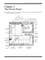
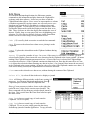
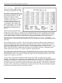
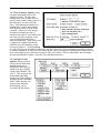
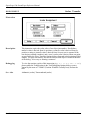
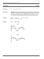
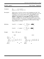
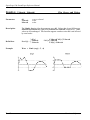
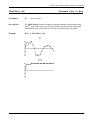
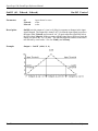
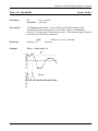
1
REFERENCE MANUAL SUPERSCOPE II & SOUNDSCOPE GW Instruments, Inc. SuperScope II & SoundScope Reference Manual October 1, 1999 Manual Version 3.0 GW Instruments 35 Medford Street • Somerville, MA 02143 Tel 617/625-4096 • Fax 617/625-1322 WEB www.gwinst.com • EMAIL [email protected] Manual by Glenn Weinreb and Stephen McCabe. Copyright © 1999 by GW Instruments. SuperScope II, SoundScope, and instruNet® are registered trademarks of GW Instruments. SuperScope II & SoundScope Reference Manual CONTENTS C HAPTER 1 WELCOME To Get Started .................................................................................................. 1-1 About This Manual ............................................................................................. 1-2 Warranty ......................................................................................................... 1-3 C HAPTER 2 THE F RONT P ANEL Introduction...................................................................................................... 2-1 Option And Cloverleaf ( ) Keys ............................................................................. 2-3 Instrument Documentation..................................................................................... 2-4 C HAPTER 3 T HE M ENUBAR Introduction...................................................................................................... 3-1 File menu ........................................................................................................ 3-2 Edit menu ........................................................................................................ 3-5 Wave menu ...................................................................................................... 3-7 Display menu.................................................................................................... 3-13 Journal menu .................................................................................................... 3-20 Task menu ....................................................................................................... 3-22 instruNet menu.................................................................................................. 3-27 Controls menu................................................................................................... 3-29 C HAPTER 4 PROGRAMMING Overview ........................................................................................................ 4-1 The Task Editor ................................................................................................ 4-2 Templates ....................................................................................................... 4-3 Program Flow .................................................................................................. 4-4 C HAPTER 5 DATA A CQUISITION Overview ........................................................................................................ 5-1 Uses of SuperScope II ........................................................................................ 5-1 The Digitizing Task ............................................................................................ 5-5 C HAPTER 6 INSTRUCTIONS Overview ........................................................................................................ 6-1 The Transfer Dialog ............................................................................................ 6-2 The String Dialog .............................................................................................. 6-4 The Variable Dialog ............................................................................................ 6-4 Alert, Beep or Delay ........................................................................................... 6-5 Arithmetic ....................................................................................................... 6-7 Assignment ..................................................................................................... 6-8 Calculate Wave ................................................................................................. 6-9 Choose Menu ................................................................................................... 6-10 Clear & Update ................................................................................................. 6-11 Curve Fit ........................................................................................................ 6-12 Datapipes ........................................................................................................ 6-13 Disk I/O ......................................................................................................... 6-14 Displays ......................................................................................................... 6-17 Filter ............................................................................................................. 6-19 Get Time ........................................................................................................ 6-22 Table Of Contents TC - 1 SuperScope II & SoundScope Reference Manual Journals & Strings ............................................................................................. 6-23 Log Marker Values ............................................................................................. 6-25 Move Marker .................................................................................................... 6-27 Programming ................................................................................................... 6-29 Pulse Analysis .................................................................................................. 6-31 Read Wave Internals ........................................................................................... 6-35 RS-232 .......................................................................................................... 6-36 Runtime Notes .................................................................................................. 6-40 Set Wave Internals ............................................................................................. 6-41 Sound Statistics ................................................................................................. 6-42 Statistics ......................................................................................................... 6-43 String Operation ................................................................................................ 6-44 Synthesize ....................................................................................................... 6-46 Scan Loop Begin ............................................................................................... 6-47 Transcendental .................................................................................................. 6-48 User Interface ................................................................................................... 6-49 User Prompt .................................................................................................... 6-51 C HAPTER 7 FUNCTIONS & OPERATORS Operators ........................................................................................................ 7-1 Complex Numbers ............................................................................................. 7-2 Waves ............................................................................................................ 7-2 Spectrum Analyzer Example .................................................................................. 7-3 Functions ........................................................................................................ 7-4 Abs .......................................................................................................... 7-4 Alarm ........................................................................................................ 7-5 Append ...................................................................................................... 7-6 ArcCos ...................................................................................................... 7-7 ArcSin ....................................................................................................... 7-8 ArcTan ...................................................................................................... 7-9 AutoCorrelation ............................................................................................ 7-10 AvgToDate .................................................................................................. 7-11 Blackman ................................................................................................... 7-12 Compress ................................................................................................... 7-13 Convolve .................................................................................................... 7-14 CopyTiming ................................................................................................ 7-15 Cos .......................................................................................................... 7-16 CrossCorrelation ........................................................................................... 7-17 CrossPower ................................................................................................ 7-18 DeConvolution ............................................................................................. 7-19 Delete ........................................................................................................ 7-20 Deriv ......................................................................................................... 7-21 DerivFivePt ................................................................................................. 7-22 Exp .......................................................................................................... 7-23 Expand ...................................................................................................... 7-24 FFT .......................................................................................................... 7-25 Hamm ....................................................................................................... 7-26 Hann ......................................................................................................... 7-27 Histogram ................................................................................................... 7-28 Imag ......................................................................................................... 7-29 IndexSort ................................................................................................... 7-30 Insert ........................................................................................................ 7-31 Int ............................................................................................................ 7-32 Integ ......................................................................................................... 7-33 TC - 2 Table Of Contents SuperScope II & SoundScope Reference Manual IntegAV ..................................................................................................... 7-34 IntegPT ..................................................................................................... 7-35 IntegTL ..................................................................................................... 7-36 IntegTV ..................................................................................................... 7-37 IntegTH ..................................................................................................... 7-38 InvFFT ...................................................................................................... 7-39 Last .......................................................................................................... 7-40 Limit ......................................................................................................... 7-41 Ln ............................................................................................................ 7-42 Log10 ....................................................................................................... 7-43 Mag .......................................................................................................... 7-44 MakeComplex .............................................................................................. 7-45 MakeIndex .................................................................................................. 7-46 Maximum ................................................................................................... 7-47 MaxToDate ................................................................................................. 7-48 Minimum ................................................................................................... 7-49 MinToDate .................................................................................................. 7-50 Modulo ...................................................................................................... 7-51 MvFFT ...................................................................................................... 7-52 OnOff ....................................................................................................... 7-53 Peak ......................................................................................................... 7-54 Phase ........................................................................................................ 7-55 PID .......................................................................................................... 7-56 PulseEndTimes ............................................................................................ 7-57 PulseMaxTimes ............................................................................................ 7-58 PulseStartTimes ............................................................................................ 7-59 Real .......................................................................................................... 7-60 Reciprocal .................................................................................................. 7-61 Reverse ..................................................................................................... 7-62 SetBit ........................................................................................................ 7-63 Shift ......................................................................................................... 7-64 SignalAvg .................................................................................................. 7-65 Silent ........................................................................................................ 7-66 Sin ........................................................................................................... 7-67 Smooth ...................................................................................................... 7-68 Sort .......................................................................................................... 7-69 Spectrum .................................................................................................... 7-70 Sqrt .......................................................................................................... 7-71 Tan .......................................................................................................... 7-72 TimeHisto .................................................................................................. 7-73 TimeValues ................................................................................................. 7-74 UnVoiced ................................................................................................... 7-75 Voiced ....................................................................................................... 7-76 C HAPTER 8 STEP -B Y -S TEP D ESIGN R EFERENCE Overview ........................................................................................................ 8-1 What is SuperScope II ......................................................................................... 8-1 Build on an Existing Instrument .............................................................................. 8-1 Six Phases of Instrument Design ............................................................................. 8-1 The Oscilloscope & Strip Chart Models ..................................................................... 8-2 The Assist Format .............................................................................................. 8-3 Tasks ............................................................................................................ 8-4 Instructions ..................................................................................................... 8-4 User Interface ................................................................................................... 8-6 Table Of Contents TC - 3 SuperScope II & SoundScope Reference Manual Displays ......................................................................................................... 8-7 Journals .......................................................................................................... 8-8 Waves, Channels, Segments & Selected .................................................................... 8-10 Markers .......................................................................................................... 8-13 Variables and Strings .......................................................................................... 8-14 Controls and Indicators ........................................................................................ 8-15 Polymorphism is Key .......................................................................................... 8-17 Datapipes ........................................................................................................ 8-18 SuperScope II Databases ...................................................................................... 8-19 Working with Tasks ........................................................................................... 8-21 Features you can add to your Strip Chart Instrument ...................................................... 8-23 A PPENDIX A INTER -A PPLICATION D ATA T RANSFER Overview ........................................................................................................ A-1 Text .......................................................................................................... A-1 16bit Integer ................................................................................................ A-2 32bit Floating Point ........................................................................................ A-2 Audio IFF ................................................................................................... A-3 System 7 8bit snd Resource .............................................................................. A-3 A PPENDIX B FILE F ORMAT Overview ........................................................................................................ B-1 Available Formats .............................................................................................. B-1 Sampling Rates ................................................................................................. B-2 A PPENDIX C SEAMS & THINGS A PPENDIX D INSTRUCTION E RROR C ODES TC - 4 Table Of Contents SuperScope II & SoundScope Reference Manual Chapter 1 Welcome Welcome to the wonderful world of SuperScope II. We are extremely excited about this product and hope you can share in our enthusiasm. SuperScope II is more than just 1 product, it is a core technology on which a number of products are based. For example, SoundScope/16 is SuperScope II with additional sound analysis capabilities. GW Instruments is committed to the SuperScope II platform and will continue to develop it throughout this decade and into the 21st Century. The current members of the SuperScope II product family are listed below: SuperScope II SoundScope/16 Basic Package Base Package #GWI-SS2 #GWI-SoS16 TO GET STARTED To get started, we recommend that you begin with Chapter 1 of the User's Manual. This Reference manual is to be used as a reference; whereas the User's Manual is intended to teach the basics. Introduction 1 - 1 SuperScope II & SoundScope Reference Manual A BOUT THIS M ANUAL This Reference manual is divided into eight chapters, summarized below: Chapter 1 Introduction Chapter 2 The Front Panel Describes the objects and controls on the front panel. Chapter 3 The Menubar Describes in detail each menu command and it's associated dialog box. Chapter 4 Programming Describes how to program using the powerful Task environment. Chapter 5 Data Acquisition Describes the Digitize Segment, programming, and hardware issues associated with data acquisition, analysis and presentation. Chapter 6 Instructions Describes the basic building blocks used to create tasks. Chapter 7 Functions Describes SuperScope II's built-in functions and operators. Chapter 8 Step-By-Step Design Reference Step-by-step instructions that provides a road map for building SuperScope II instruments. 1 - 2 Introduction SuperScope II & SoundScope Reference Manual W ARRANTY GW Instruments, Inc. warrants that the Products furnished under this Agreement will be free from material defects for a period of one year from the date of shipment. The Customer shall provide notice to GW Instruments of any defect within one week after the Customer’s discovery of such defect. The sole obligation and liability of GW Instruments under this warranty shall be to repair or replace, at its option, without cost to the Customer, the product or part which is so defective and about which such notice is given. Upon request by GW Instruments, the product or part claimed to be defective shall be returned immediately to GW Instruments at the Customer’s expense. Replaced or repaired products or parts will be shipped to the Customer at the expense of GW Instruments. There shall be no warranty or liability for any products or parts which have been subject to misuse, accident, negligence, failure of electric power, or modification by the Customer without GW Instruments’ approval. Final determination of warranty eligibility shall be made by GW Instruments. If a warranty claim is considered invalid for any reason, the Customer will be charged for services performed and for expenses incurred by GW Instruments in handling and shipping the returned item. The warranty period of replaced or of repaired products will terminate with the termination of the warranty period of the original product or part. THE FOREGOING WARRANTY CONSTITUTES GW INSTRUMENTS’ SOLE LIABILITY AND THE CUSTOMER’S SOLE REMEDY WITH RESPECT TO THE PRODUCTS AND IS IN LIEU OF ALL OTHER WARRANTIES, LIABILITIES AND REMEDIES. EXCEPT AS THUS PROVIDED, GW INSTRUMENTS DISCLAIMS ALL WARRANTIES, EXPRESSED OR IMPLIED, INCLUDING ANY WARRANTY OF MERCHANTIBILITY OR FITNESS FOR A PARTICULAR PURPOSE. Apple, Macintosh and LaserWriter are registered trademarks of Apple Computer, Inc. MacRecorder is a registered trademark and SoundEdit is a trademark of Farallon Computing, Inc. Audiomedia is a registered trademark of Digidesign, Inc. Apple VideoRoommates is a registered trademark of Bose Corporation. instruNet, SuperScope, SoundScope, SoundScope, SuperScope II, MacADIOS and MacSpeech Lab are registered trademarks of GW Instruments, Inc. Introduction 1 - 3 SuperScope II & SoundScope Reference Manual 1 - 4 Introduction SuperScope II & SoundScope Reference Manual Chapter 2 The Front Panel The SuperScope II front panel is composed of objects that are easily created, resized, and positioned by the user. A typical front panel is illustrated below. title bar marker name horiz marker value vert value auto vertical scale adj auto horizontal scale adj status bar titlebar journal vertical scroll horiz. scroll grid plot region PICT vertical axis label marker wave vertical position (scrollbar) wave label vertical adjust icon vertical scale (adjust.) selected wave wave label region segment The Front Panel horizontal position (scroll) horizontal axis label horizontal scale (adjustable) 2 - 1 SuperScope II & SoundScope Reference Manual The title bar can be used to move the front panel around the screen by clicking and dragging. The title bar also indicates the name, if any, of the current instrument. If the instrument has not yet been named, the title bar simply shows the product name. The status bar indicates the current status of SuperScope II. The status bar is typically empty (i.e. everything is OK) and only shows a message occasionally. For example, if two displays overlap in Panel Edit mode, "Invalid Panel" is shown. The resize box at the lower right of the front panel can be used to resize the entire front panel by clicking and dragging until the desired size is achieved. The objects on the front panel are resized proportionally to the front panel window, or remain fixed in size, as specified by radio buttons in the Panel Options dialog. Resizing can only be done when Panel Edit is On. Also, SuperScope II prohibits shrinking displays below a practical minimum size to ensure readable content. The optional horizontal scale control, located at the lower right of each display, controls the horizontal scale used for plotting waves, in terms of horizontal units/div. The scale can be changed by clicking on the scale arrows. The optional horizontal scrollbar, located at the lower left of each display, controls the horizontal position used for plotting waves. The position can be changed by clicking on the arrows, clicking in the gray page left/right region, or by dragging the thumb. The optional display label indicates the contents of each display with user define text. This text is shown in the upper left corner of each display and is both enabled and defined in the Display Features dialog. The display region is used to graphically display waveforms as dots, line segments, or bars. The optional wave label region, located along the left edge of a display, labels the waves in the display. This feature is enabled/disabled, for each display, in the Display Features dialog (via ). The Finder uses a noun-verb metaphor with it's icons. The user first selects an icon (noun) and then operates on it (verb) with a menu command or keypress. The SuperScope II front panel uses the same noun-verb metaphor. The user selects a front panel journal, display, or wave within a display with a simple mouse press; and then operates on that object (e.g. enter notes into a journal, edit a wave segment, etc). It is necessary to do this with multiple targets since the computer needs to know where to direct mouse and keyboard activity. When a front panel journal is selected, it's scrollbars become active. Once active, all keyboard activity are directed to the journal. To select a display, click the mouse anywhere within the display or label regions. Double-clicking the wave label region of a selected display opens its Display dialog, and is equivalent to choosing the Display command for that display. When a display is selected, one of it's wave labels becomes highlighted to indicate that this wave is selected within the display. Wave labels, located in each wave label region, correspond to the names of each wave in that display. These labels will not appear if the Add Wave Labels option is turned off in the Display Features dialog. A waveform can be selected by clicking it's wave label (this causes it's label to become highlighted). A selected wave can be modified using the mouse modes (Edit, Draw, Move Marker, Log Coords, Vertical Adjust) which are described under the Mouse command in the Display menu. Double-clicking a wave label causes it's Wave dialog box to appear. This action is 2 - 2 The Front Panel SuperScope II & SoundScope Reference Manual equivalent to choosing the Wave command for that wave. To de-select a waveform without selecting another one, click anywhere in the wave label region not occupied by a wave label. If there is only one wave in a display, selecting that display causes the one resident wave to become selected, independent of whether or not the wave label region is shown. O PTION A ND C LOVERLEAF ( ) KEYS All tasks can be stopped by choosing cloverleaf period ( .). To learn about undocumented Option and keys; please open file (choose Open... under Journal) "!Hidden Features.note" in the "Programmer's Notes" folder inside the "Goodies" folder. This file expects tabs every 4 characters (i.e. choose Options... under Journal and then set the Tabs to "4" characters). The Front Panel 2 - 3 SuperScope II & SoundScope Reference Manual INSTRUMENT D OCUMENTATION To copy a complete textural description of your instrument to the clipboard, press Shift Option 'A'. To view or print the description, paste the text into a word processor or into a journal. If a journal by the name of "ReadMe" exists, it's text is included in the description. A journal by this name is the standard repository for user documentation of an instrument If the user presses Option 'a' (i.e. lower case 'a'), a more brief textural description of the instrument is sent to the clipboard. The brief version does not include the ReadMe or the Menubar text. These documents look best when printed with a small fixed character width font such as Courier 9. A fragment of the Option 'a' text is shown below: •••••••••••••••••••••••••••••••••••••••••••••••••••••••••••••••••••••••••••••• INSTRUMENT • INSTRUMENT • INSTRUMENT • INSTRUMENT • INSTRUMENT • INSTRUMENT Name: .sos5 Date: 8/12/92 Application: SoundScope/16 Version: 1.0ß9.84 •••••••••••••••••••••••••••••••••••••••••••••••••••••••••••••••••••••••••••••• DISPLAYS • DISPLAYS • DISPLAYS • DISPLAYS • DISPLAYS • DISPLAYS • DISPLAYS Display Name -----------time analysis snap D4 •••••••••••••••••••••••••••••••••••••••••••••••••••••••••••••••••••••••••••••• WAVES • WAVES • WAVES • WAVES • WAVES • WAVES • WAVES • WAVES • WAVES • WAVES Wave Name Wave Type V Units H Units Length ValidPts ----------------------------------------------------------------------time Integer Volt sec 44509 44509 snap Float dB Hz 256 256 analysis Float Volt sec 0 0 W1 Integer Volt sec 0 0 ••• Wave Mapping For 16bit Integer Waves ••• Wave Name Quanta Min Code Max Code Min Value Max Value ----------------------------------------------------------------------time 0.000305 -32768 32767 -10.000000 9.999695 W1 0.000305 -32768 32767 -10.000000 9.999695 ••• First 5 Points ••• Wave Name Point#1 Point#2 Point#3 Point#4 Point#5 -------------------------------------------------------------------------------time 0.000000 0.000000 0.000000 0.000000 0.000000 snap 0.000000 0.000000 0.000000 0.000000 0.000000 analysis W1 2 - 4 The Front Panel SuperScope II & SoundScope Reference Manual Chapter 3 The Menubar This chapter describes all commands in the SuperScope II menubar, in menubar order. This chapter is a comprehensive source of detailed information in encyclopedic form. To develop the level of understanding assumed by this chapter, it is recommended that you first do the Tutorial in the instruNet User's Manual and also the Tutorial in the SS II User's Manual. The Menubar 3 - 1 SuperScope II & SoundScope Reference Manual File Menu In many Macintosh applications, the File menu contains all commands that interact with the disk (e.g. Open, Save) and that deal with the entire file or document (e.g. Page Setup, Print). But typical applications only deal with one kind of document or object. In contrast, SuperScope II includes many different objects, such as displays, waves, journals and tasks. Each of these objects has its own menu for loading, saving and printing (if applicable). Together, they comprise a software instrument. The SuperScope II File menu deals with the entire instrument. New Instrument clears all displays, markers, waves, journals, tasks and datapipes from memory; and lets you create your own instrument from scratch. SuperScope II can only have one instrument active at a time. Open... ( O) lets you select a pre-defined instrument file from disk to replace the current instrument. Unless you press Cancel, all displays, waves, journals, tasks, datapipes, etc will be cleared from memory, and replaced by new ones. All changes that have not been saved will be lost (careful!). Save... ( S) writes the instrument configuration to disk using the current instrument name (shown in the title bar), effectively deleting the previous version. An Instrument Designer has some control over which information is saved with the instrument. The name and attributes of all objects are always saved. To make sure their contents (data) are saved, verify that the appropriate Save Contents With Instrument File checkboxes are selected. (In Full Menus, select the Options under Wave menu, and click the Points button. Also, choose Options under Journal. For more information, see the wave and journal discussion later in this Manual). Saving wave and journal contents with the instrument is a convenient way of letting you start up exactly where you left off. Note that this additional information can increase the instrument size greatly. Save As... prompts for a file name and location with the standard File dialog, and then saves the instrument to disk. Option-Shift 'S' will bring up the Save As dialog. What is a Datapipe? A datapipe is a reference to a folder on a hard disk or floppy disk. Technically, a datapipe is a pathname to a folder. Think of it as a pipe, through which you send data between SuperScope II and a folder on disk. Datapipes are often used to access folders from within tasks, where the name of the folder may change with each experiment. The Datapipe instruction can be used to create a new data folder, and to attach a datapipe to that folder. The Disk I/O instruction could then be used to push data into the datapipe, and ultimately into the new folder. Datapipes, like other SuperScope II objects, are created, deleted, and named. To view or modify a datapipe's folder, choose Datapipe Folder under File. Datapipe... is used to adjust and view the datapipe pathname, edit the datapipe name, and enable/disable the datapipe on/off ( 'U') feature. Choosing Datapipe causes a submenu to appear with a lists of existing datapipes and a New Datapipe command. Selecting New Datapipe causes a datapipe to be created, and selecting an existing datapipe causes it's options box to appear, shown below. 3 - 2 The Menubar SuperScope II & SoundScope Reference Manual The upper-most pop-up menu determines which datapipe is being viewed. The Name field allows you to change the name of the datapipe. If the Turn On and Off box is enabled, the datapipe can be switched on and off during task execution by hitting the keys, Command U ( 'U') . Files saved and loaded via datapipe proceed normally if the datapipe is "On"; otherwise, the file transfers do not occur. This is useful if you are recording and want to save (or not save) a particular interesting range of data. The datapipe's pathname is shown in the Folder area. For example, in the above dialog, the datapipe points to folder "SS II tutorial Inst's", inside folder "'SS2 src", which resided in the "gswHD" hard disk. To modify the pathname, press the Folder button. Delete Datapipe... causes a submenu to appear with a list of all currently defined datapipes. Selecting a datapipe from the submenu causes SuperScope II to first issue a warning, and then, upon receiving your confirmation, delete the datapipe from memory. Datapipe Folder... lets you change the folder pointed to by a datapipe. Delete File... is used to delete any file that has been created. SuperScope prompts for confirmation before it deletes a file. Deleting a file deletes its definition as well as its contents. Page Setup... presents the standard dialog for the current printer (specified from the Chooser in the Apple menu). For example, the LaserWriter dialog is shown to the right. Refer to your printer documentation for detailed explanations of the available settings. Print Setup... lets you select the objects to print. You may print the entire Front panel or one or more Displays, using horizontal and vertical scales according to the Front panel setting or Fit to page. Printout shows you the Current length, and lets you set a maximum number of pages to print. The Menubar 3 - 3 SuperScope II & SoundScope Reference Manual Print... ( P) presents the standard Macintosh print dialog, similar to the one shown to the right. You may simply click OK or hit the Return key to print. Refer to your printer documentation for detailed explanations of the available settings. Quit ( Q) leaves SoundScope, returning you to the Finder (the desktop). All changes that have not been saved will be lost. Be careful, there is no warning prompt. 3 - 4 The Menubar SuperScope II & SoundScope Reference Manual Edit Menu As with most Macintosh applications, the Edit menu contains commands to edit information and place data on the Clipboard for exchange with other software. It also lets you show or hide the Clipboard and other objects. Since waves are represented as a column of numbers separated by carriage returns, one can easily move wave data between SuperScope II, spreadsheets, word processors and graphics programs. To select part of a wave with the mouse, make sure that the Mouse mode (under the Display menu) has been set to Edit. Then, click once to select the display that contains the wave of interest. Finally, drag over any part of the wave, highlighting your selection. To select text in a journal, click once on the journal then double-click on a word or drag over any amount of text. Undo ( Z) is used by desk accessories to undo the last command. Cut ( X) removes the selected wave data or text, placing it on the Clipboard. Copy ( C) places the selected data on the Clipboard without altering original. Paste ( V) is used in a number of ways. In a wave, if the cursor is a cross-hair (i.e. Mouse Edit is selected under Display), Paste inserts the wave data stored in the Clipboard at the cursor position. (It inserts nothing if the Clipboard contains non-numerical text.) If part of the wave is selected, the Clipboard data overwrites the selection. (If the Clipboard contains non-numerical text, Paste has the same effect as Clear, i.e. it deletes the selection without inserting any data in its place.). In a journal, Paste inserts the text stored in the Clipboard at the cursor position. (It inserts a the wave values if the Clipboard contains wave data.) If some text is already selected, the Clipboard data overwrites the selection. Clear removes the selected wave data or text, without altering the contents of the Clipboard. Select All ( A) selects all data in the active display or journal. Show will bring a different window to the front, creating it if necessary. As with most Macintosh applications, Show Clipboard opens a window onto the Clipboard data. Show Cursor presents a window, shown to the right, that tracks the wave values for the current cursor location. The Show command will also bring any window-based journal to the front. This is useful since the Front Panel often occupies the entire screen. Copy Task places a textual copy of a task onto the Clipboard. To save or print, Copy Task places a textual copy of a task onto the Clipboard. To save or print, simply paste the data into a SoundScope journal or another application. To copy all tasks The Menubar 3 - 5 SuperScope II & SoundScope Reference Manual to the clipboard, press Option Shift 'O'. To copy a description of the entire instrument to the clipboard, press Option 'a'. To copy a description of the entire instrument, including menubars, to the clipboard, press Option Shift 'a'. Copy Display places a visual copy of a display (in PICT format) onto the Clipboard. To create a report or presentation, simply paste the data into another application. Copy Wave Text places wave values (in text format) onto the Clipboard. To save, print, plot or analyze the data, simply paste into a SoundScope journal or another application. Copy Wave Graph places a visual copy of a wave (in PICT format) onto the Clipboard. To create a report or presentation, simply paste the data into another application. Choose Menubar lets you select SoundScope's Full menus, or any other menubar created by an Instrument Designer. To copy a description of the current menubar to the clipboard, press Option 'p'. To copy all menubars, press Option Shift 'P'. Edit Menubar... is used to create, define, and modify entire menubars. Edit Menubar opens the Menubar Editor, which is a powerful environment for defining your own menubar; and hence, designing your own menu-driven application program. One can create a menubar bar by choosing New Menubar in the Custom Menubar pop-up. Menus are easily deleted by pressing the Delete button while they are selected in the pop-up at the top of the dialog. One can have an unlimited number of menubars, one of which is always in use as specified by Choose Menubar under Edit. In the Menubar Editor, selecting Use Default Text causes the default menu or menu item text to appear. Selecting Use Custom text allows you to rename a menu or menu item. Selecting Hide allows you to hide a menu or menu item. Selecting New User Item in the Item pop-up causes a new menu item to appear at the end of the menu. This new item can then be renamed, hidden, or setup to run a task when selected. Tasks provide the functionality for user defined menu items. Option-Shift 'M' will open the Menubar editor and Option-Shift 'S' will open the Save As dialog. These are useful if the menu commands are hidden. 3 - 6 The Menubar SuperScope II & SoundScope Reference Manual Wave Menu The Wave menu contains commands that you perform on waves. Each item is a hierarchical menu with which you choose an entire wave (by name), a named segment (which is defined in the Marker dialog as the portion between two markers) or the currently selected portion (if something has been selected). Note that both the raw data and the results of most calculations are stored as waves, and that wave data is either stored as 16bit integers or 32bit floating point values (defined in the Format dialog which is opened from the Wave dialog) New... ( W) creates a new wave and then opens it's options dialog, described below. Options... opens the Wave Options dialog; which is used to edit a wave's name, data storage format (i.e. 16-bit integer or 32-bit float), number of points, and actual data. All wave names can be up to eight characters long and must be unique. SuperScope II is case sensitive (e.g. "bubble" and "Bubble" are two different labels). The Units box specifies the vertical engineering units, which are used for labeling purposes. The Place Wave Into Display pop-up is used to pop the wave into the specified display when OK is pressed. The If Wave Changes, Run Task checkbox and pop-up is used to setup the running of a task when the wave's data changes. For example, if task T1 does "W1 = Deriv(W2)", one could setup T1 to run when W2 changes, insuring that W1 will always be seen as the derivative of W2, no matter what. The Link to instruNet option links a SuperScope II wave to an instruNet input or output channel. To digitize from instruNet hardware, an input channel must be linked to a SuperScope II wave. Pressing the Channel button opens the instruNet Channel Selection dialog where a specific channel is chosen with it's network#, device#, module# and channel#. Pressing the Comments button causes the Comments box to appear, which provides a place to keep notes with each wave. Pressing the Edit button invokes the table editor, which is described under the Edit Values command in the Wave menu. Pressing the Synthesize button invokes the wave synthesizer's dialog box, which is described under the Synthesize command in the Wave menu. This box is useful for loading a wave with a constant value, ramp, sine wave, triangle wave, square wave, gaussian noise (gaussian distribution), or uniform noise (flat histogram). Pressing the Revert button in the Wave dialog reverts all values except data to what they were when the dialog first appeared, canceling all changes. The Menubar 3 - 7 SuperScope II & SoundScope Reference Manual The Points... button opens the Points dialog. This box enables one to view and edit parameters related to the actual data. Fields are provided to view and edit the amount of data storage (in points) assigned to the wave, the number of valid data points, the sample period (time between points) and the first point time. The storage length is the amount of memory allocated to the wave in terms of # of points, and the number of valid data points is the # of valid data currently in that storage buffer. The # of valid points will range from 0 to the storage length, and the storage length will range from 0 to that permitted by available memory. 16bit integers consume 2bytes per point and 32bit float consume 4 bytes per point; therefore a 250K point float wave would consume 1MB, for example. If Save Data With Instrument File is checked, SuperScope II will save the wave's data in the instrument file. If it is not checked, the wave is saved with 0 points of data. Note that including wave data in an instrument file increases the size of that file by the space required to hold that data. The Format... button opens the Format dialog, which is used to specify the internal storage format for a wave's data. Waves can be stored as a series of 32bit Floating Point or as a series of 16bit Integer values. The default format for all waves is 32-bit, and waves linked to instruNet input or output channels must be of type 32-bit float. 32bit floating point waves are stored directly as engineering units (i.e. you view and analyze the same value that is stored internally; this is not the case with 16bit integer waves). 16bit integer waves are stored as 16bit integers (e.g. -2048, 16384), and are mapped to engineering units (e.g. 5V, -3V), as specified in this dialog. The minimum and maximum specified internal values are mapped to the minimum and maximum specified engineering unit values, respectively (e.g. ±32768 internal is mapped to ±10Volts engineering units). Internal values can range from -32768 to +32767. Also beware that 16bit integer values can overflow if the computer tries to load them with a number larger than their max/min engineering unit value (e.g. ±10V). When this occurs, the data is often set to the closest bound. For example, if we do W1=W2+W3, and all three waves have a ±32768 to ±10V mapping, and are loaded with 8V, the result will be set to 10V, not 16V. Beware that 16bit integer waves have limited resolution. For example, the values in a ±32768 to ±10V mapped wave are accurate to 0.000305V = 10V/32768. This means that you could set the wave to 0.000305V, 0.0, 0.000305V, 0.000610V; yet to nothing in between. An attempt to do so would result in a rounding to the nearest value. To convert a 16bit integer wave to 32bit float, press Format in the Wave Dialog, and then choose Floating Point. 3 - 8 The Menubar SuperScope II & SoundScope Reference Manual Calculations with 32bit floating point waves are faster than with 16bit integer waves since the computer does not need to map from internal units to engineering, do the calculation, and then map back to internal units. Delete disposes of the wave selected in the delete submenu. Once a wave is deleted, it’s gone. Unless it was saved, there is no recall. Open... lets you select a wave file on disk, and then loads that wave and it's data into SuperScope II. The new wave is added to the list of waves. This is similar to Load Wave, except Open causes a new wave to appear, and Load loads data into an existing wave. Save As... writes to disk the data in the wave that you select, prompting you for a filename and location (folder). Like all standard File dialogs, the pop-up menu at the top lets you move "up" in the folder hierarchy. As an alternative, the Folder pop-up menu in the bottom right corner lets you select a datapipe as the destination folder. If no datapipes exist, it will simply show the current folder. The Format... button lets you change the file format and other parameters. The default format is 16-bit integer or 32-bit floating point, depending on the internal data type. (To check or change the type, switch to the Full Menubar, select the Options command from the Wave menu, and click on the Points button.) The data can be saved as Text for use in another application. The Audio IFF (AIFF) format is an emerging industry standard for sound. See Appendix A, Transfer Wave Data, and Appendix B, File Formats for additional information. The Data options let you save only a subset of the wave, and the Append choices will annotate the filename with useful information. As noted earlier, wave data can also be saved with the instrument. Load Data... lets you select a wave file on disk, and then loads its data into an existing wave. The new data will overwrite the old data (careful!). Append... lets you select a wave file on disk, and then appends its data to an existing wave. The Menubar 3 - 9 SuperScope II & SoundScope Reference Manual Edit Values... organizes wave values in a table for simple viewing and editing, as illustrated to the right. The leftmost column in the table is an index which corresponds to the point in the adjacent column (e.g. in the dialog to the right, the value at .00048sec is .044Volts). This index is shown in units of time (e.g. seconds) or point number (i.e. an incrementing integer, starting with 1), depending on the setting of the Index radio buttons. The five rightmost columns hold the wave data, proceeding left to right then top to bottom. There is no way to cancel or undo changes made in this dialog. To change the value at any point, just click on its cell and type a new number. Use the arrow keys to move the cursor up, down, right and left between cells. Depending on the Typing option, both the Tab and Return keys will either move the cursor to the right (Overwrite mode) or insert a new cell (Insert mode). To select a range of values, simply drag the mouse over any series of cells. Although the File menu is disabled, the keyboard equivalents for Cut ( X), Copy ( C), and Paste ( V) work as expected. The Delete key has the same effect as Cut, and the Enter key will accept changes and exit the dialog. Several display options are available. The two Format radios determines whether points are displayed in Decimal or Hexadecimal form (e.g. decimal 25 in hexadecimal form is 0x019). Hexadecimal can only be selected when displaying 16bit integer Internal data. The Units option specifies whether values are displayed in engineering units (e.g. -10 to +10Volts values) or Internal units (e.g. -32768 to +32767 values from a 16bit A/D converter). Internal units only apply to 16-bit integer waveforms. Independent of the display options, data is always Cut, Copied, or Pasted in engineering units. The Typing option controls the behavior of the Tab and Return keys. In Overwrite mode, pressing Tab or Return moves the cursor one cell to the right. In Insert mode, Tab or Return inserts a new cell, increasing the total length of the wave by one point. Finally, the upper-most Wave pop-up menu allows you to select another wave, segment, or selection. Caution: Only 3 digits after the decimal are shown in the Wave Editor, yet more precision is stored internally. 16bit integer waves often have a least-significant-bit value of 0.000305 (i.e. 20/65536) and 32bit floating point waves offer 7 significant digits of scientific notation accuracy (i.e. ±X.XXXXXX e ±YY). Copy Wave Text in the Wave menu is a more accurate way to copy wave data to the clipboard. Pasting into the Wave Editor is very accurate and does not involve unnecessary truncating. If you select a cell and move to another cell, it will read the text if it differs by more that .001 from the value stored internally and update the internal value to that (truncated) viewed value (careful!). 3 - 10 The Menubar SuperScope II & SoundScope Reference Manual Synthesize... allows you to load waves with internally-generated (i.e. synthesized) data. Waves can be loaded with a sine wave, square wave, triangle wave, ramp, constant value, gaussian noise, or uniform noise. Sine, Triangle and Square waves are defined with the Points-per-cycle and Peak-to-Peak Amplitude fields. The Ramp is define with two fields that specify the value at the two end points. Gaussian noise has a gaussian distribution (i.e. a histogram of the wave data is a gaussian curve centered about 0) with the specified RMS (Root Mean Square). RMS is the same as standard deviation is this case. For example, 10Vrms gaussian noise will have 60.6% of it's values between -10 and +10V. Uniform noise is evenly distributed about the specified bound. A histogram of uniform noise shows values evenly distributed between -Bound and +Bound. For example, each point of ±10V uniform noise has an equal probability of appearing anywhere between -10V and +10V. The Length edit field is used to specify the # of points in the synthesized wave, the maximum being that permitted by available memory. The wave is loaded with synthesized data when the user presses the OK or Do It button. Calculate... is used to perform waveform calculations. Over 80 functions and operators (e.g. fft, cos, +, *) are supported. The calculation takes place only when the Do It button is pressed. For details on this dialog box, please consult the Calculate Wave instruction (which is identical to the Calculate command under the Wave menu) in Chapter 6, Instructions. For details on each function, please refer to Chapter 7, Functions & Operators. Filter... is used to run a low-pass, highpass, band-stop, band-pass or user defined FIR filter on a wave, segment or selection. For details on this dialog box, please consult the Filter instruction (which is identical to the Filter command under the Wave menu) in Chapter 6. The Menubar 3 - 11 SuperScope II & SoundScope Reference Manual Wave Statistics... provides general information on the designated wave, segment or selection. Depending on the wave size, you may have to wait several seconds for the data to appear. The Wave pop-up menu at the top allows you to view statistics for a different wave, segment or selection. 3 - 12 The Menubar SuperScope II & SoundScope Reference Manual Display Menu The Display menu controls your interaction with the SuperScope II front panel and it's displays. It includes commands to control marker location and various choices for mouse behavior. Additionally, it contains commands that create and customize display, markers, and waveform segments. New..., Options..., and Delete create, modify and dispose of displays. Controls..., Features... and Labels... are used to specify attributes of existing displays. Marker... is used to create, rename and dispose of markers and segments. Marker objects represent a time (e.g. .1 seconds) and are viewed as a vertical line in a display (after being placed into that display via the Marker dialog). They are often used to identify and mark interesting points or regions within a waveform. Segments are waves themselves that are defined as the section of another wave between two markers. For example, wave W1 is a 0 to 1V ramp between 0sec and 1sec. Segment Seg1 is defined as the section of W1 between M1 and M2. If M1 is at .1 sec and M2 is at .2sec, then Seg1 would be a .1V to .2V ramp from .1sec to .2sec, and would share W1's data (i.e. if you draw on one, you will draw on both). New... ( D) creates a new display and then opens the Display Options dialog, described below. Options... opens the Display Options dialog; which is used to specify the type, the contents, and the visual characteristics of a display. The Display pop-up menu at the top of every Display dialog box indicates which display's parameters are being viewed or changed. Selecting New Display from this pop-up creates a new display with default values for all the parameters. Should a new display exceed the front panel capacity, a warning appears. In this event, you can create room on the front panel by resizing existing front panel items while in Panel Edit mode. The Name edit field allows you to change the display name (caution: two displays cannot have the same name). The Type pop-up menu selects the type of graphs to be displayed, such as XY Plot or Wave Plot. In Wave Plot displays, SuperScope II plots the wave points in order, from first to last, across the screen. In XY Plot displays, SuperScope II plots one wave against another, point for point. For example, if W1 is plotted against W2, SuperScope II plots the point (W1[1],W2[1]), then the point (W1[2], W2[2]), and so on. The Waves list shows the names of all waves and channels in memory; and the Contents list shows which waves are shown in the display.. To place a wave into a display, drag it's wave name from the Wave list to the Contents list. A Wave Plot display needs one wave for each plot; whereas the XY Plot needs two. To remove a wave from the display, drag its name out of the Contents list. To replace one wave with another, drag the name of the new wave onto that of the old wave as it appears in the Contents list. To change the color of the plotted wave, make sure your monitor is in Color mode and then double-click on the wave name as it appears in the Contents list. A color picker will appear. Click once on the desired color and then press OK. Pressing the Comments button causes the Comments box to appear, which provides a The Menubar 3 - 13 SuperScope II & SoundScope Reference Manual place to keep notes with each display. The Controls..., Features... and Labels... buttons lead to dialog boxes that are used to adjust visual attributes and controls in each display. The Marker... button leads to a dialog that is used to create, rename and dispose of markers and segments. For more information on Controls, Features, Labels and Markers, please see their respective sections in the next few pages. Please refer to the Front Panel chapter for a labeled illustration of displays, markers and segments. Delete... disposes of the display selected in the delete submenu. Once a wave is deleted, it’s gone. Unless it was saved, there is no recall. Move... shifts a display, moves a marker or both. For displays, the first Position option shifts the contents by the specified amount. To move left, enter a positive number; to move right, enter a negative number. Note that "moving" the display contents left is equivalent to pushing an imaginary piece of graph paper to the left. An unfortunate (but arguably unavoidable) subtlety of the Macintosh user interface is that "moving" left is equivalent to "scrolling" right. The second option sets the left edge of the display to the specified value, and the third sets the left edge to the marker position. For markers, the first Position option moves the marker by the specified amount. To move left, enter a positive number; to move right, enter a negative number. The second option moves the marker to the specified value, and the third to the position of another marker. Mouse... is used to select one of five mouse modes: Edit, Draw, Move Marker, Log Coords, or Vertical Adjust. In each mode, the operation of the mouse relates to a single wave in a display that has been selected. If a display includes more than one wave and you need to operate on a wave other than the first (as viewed in the Contents list of the Display Options dialog), wave labels must be visible. To enable wave labels, select Features from the Display menu (which is available in the Full Menubar), and click on the Add Wave Labels checkbox. The first four letters of each wave name are shown in the wave label area, and clicking on a wave label selects that wave for mouse work. Edit ( 1) is the most commonly used mode and is automatically selected when you first launch SoundScope. In this mode, you can Cut, Copy and Paste sections of a wave much like one would edit text in a word processor (i.e. by dragging the mouse over the area of interest). The selected portion is highlighted and magically becomes a waveform of its own called "Selected". The Selected wave appears in wave submenus, shares data with the host wave, and is viewed as an ordinary waveform by the analysis and presentation tools. Only the user can change the length of the Selected wave (i.e. with the mouse). Draw ( 2) changes the cursor to a pencil and allows you to edit the wave data graphically. When the mouse button is held down, the pencil leaves a mark everywhere it is dragged. When the mouse button is released, the wave is updated with the drawing. If the Grid Snap On option is selected the mouse drawing will be restricted to straight lines. 3 - 14 The Menubar SuperScope II & SoundScope Reference Manual Move Marker ( 3) changes the cursor to a " ", which is used to move markers. If Move Marker mode is not selected, you can still move markers by holding down the Option key while dragging the mouse. Log Coords ( 4) changes the cursor to a cross-hair, which is used to log wave coordinates to a Journal. Each time the mouse is clicked on a wave, it's position (usually time) and value are sent to a journal. The coordinates are preceded with a header on the first click, as shown in the above illustration (e.g. "X:Hz Y:dB"). The Log Coords To submenu specifies which journal receives the text. Vertical Adjust ( 5) changes the cursor to a hand, which is used to move the selected wave up and down in its display. Moving a wave is purely a graphical operation and does not affect the wave data. Clicking once on the " " symbol next to the wave name will cause that wave to snap back to it's non vertically adjusted position. Grid Snap On/Off is used by the Draw mouse mode, described above, to lock the cursor at specific grid intervals while drawing. Log Coords To is used by the Log Coords mouse mode, described above, to specify which journal receives coordinate data. Controls... is used to specify a display's horizontal and vertical scale and position controls. The Horizontal and Vertical Position pop-up menus select the method for determining the left edge and middle horizontal, respectively, of a display (and therefore what portion of the wave is viewed). The Horizontal and Vertical Scale pop-up menus select the method for determining the scale along the horizontal and vertical axis, respectively, of a display. The Fix Sample Period checkbox is used to override the sample period of each wave with the one specified in the edit field. The various position and scale control options are described below: Adjustable is used to specify a scale with arrow buttons. Scrollable is used to specify a position with a standard Macintosh scrollbar. Fixed sets the scale or position to a value specified in the Controls dialog. Fixed Base sets the bottom edge of a display to the value specified in the Controls dialog. This is similar to Vertical Position Fixed, yet pegs the bottom of a display instead of the middle. Previous sets the scale or position to that used in the previous display, as viewed in the Display submenu. The Menubar 3 - 15 SuperScope II & SoundScope Reference Manual Next sets the scale or position to that used in the next display, as viewed in the Display submenu. Continue sets the horizontal position such that the wave plotted in the previous display, as viewed in the Display submenu, continues where it left off in this display (e.g. 0sec to 1sec is plotted in D1, and D2 continues with 1sec to 2sec). Features... is used to specify the graphic characteristics of the plot region and label areas. The Plot pop-up menu allows you to specify how points are to be plotted: Lines connects points with straight lines ( ), Dots plots dots at each point ( ), Tagged Lines connects points with straight lines and overlays symbols ) every ( 32pixels or so, Symbols plots symbols, and Bars draws a vertical bar at each point ( ). The Background pop-up menu allows you to specify the display background color in Blue, White, or Black. The Grid pop-up menu allows you to select the background grid pattern of the display. Some grids take an appreciable amount of time to draw. On the Macintosh Plus and Macintosh SE, the fastest grids are the 8x8 and 8H The Hide entire display box is used to hide a display. This option can be set in a SuperScope II task using the "Displays" instruction. Add Label is used to indicate the contents of each display with user defined text in the display's upper left corner. Add wave labels is used to enable the wave label region, which shows the name of each wave in the display. The five Mouse modes (Edit, Draw, Move Marker, Vertical Adjust, Log Coords) operate on the selected wave, and a wave is selected by clicking on one of these labels. The Horizontal and Vertical Units boxes are used to override a wave's units label (e.g. "mmHg"), and the Horizontal and Vertical Axis Label checkboxes are used to enable/disable the axis labels themselves. The default horizontal scale is time in seconds. To change the horizontal scaling to hours, minutes and seconds click the hrs:min:sec box. 3 - 16 The Menubar SuperScope II & SoundScope Reference Manual Markers... is used to create, dispose and rename markers; to define, create, dispose, and rename segments; and to specify which markers are to be visible in each display. The Marker pop-up lists all currently defined markers. Selecting a marker from this submenu displays that marker's name and its window width in milliseconds. The Name field allows you to assign or change the marker name. Since each marker name must be unique, SuperScope II rejects a repeated name and prompts for a new one. Checking the Window box causes a diamond frame of the specified width to be affixed to the vertical marker indicator in the displays. This is used to indicate the window width when doing analysis on the section of wave about a marker (e.g. marker is at .1sec and you do an FFT on the section between .075sec and .125sec). Clicking the New button creates a new marker with a default name. Clicking Delete causes the displayed marker to be deleted. A neat trick is to use two markers and one wave to describe another wave, called a "segment", which is defined as the section of the original wave from one marker to the next. Since segments and their parent wave share the same data, changing the data in one will change the data in the other. The Segment pop-up lists all currently defined segments. The Name field allows you to assign or change the segment name. The Wave pop-up allows you to select the wave on which the segment is based. And the Left and Right popups are used to specify which markers define the end points of the segment. The New button creates a new segment with a default name. The Delete button erases the displayed Marker. The Display section is used to specify which markers are shown in each display (as a vertical line). This is done by clicking once on a marker name as it appears in the Show Markers area (it will highlight) while the desired display is selected in the above pop-up. Clicking again will de-select the marker, and hence take it out of the designated display. One can view any number of markers in each display, and each marker can appear in any number of displays. Labels... is used to setup the labeling of markers and marker related information. Although any number of markers may appear in one display, only two markers may be represented in the marker label line, as illustrated below. The Display pop-up menu selects which display is represented in the dialog. Each Marker pop-up menu selects one marker to be labeled. The Show X value, Show Y value and Show marker name checkboxes are used to activate their corresponding labels. The Menubar 3 - 17 SuperScope II & SoundScope Reference Manual delta X delta Y delta Y/X marker name X value Y value Marker M2 Marker M1 marker name X value Y value The Delta Values area allows you to display any of three different statistics. Checking Show delta X will display the difference between the horizontal value of the first marker and that of the second. Checking Show delta Y displays the difference between the vertical values of the two markers. Checking Show delta Y/delta X displays the slope between the two points defined by the markers and the wave selected in the Show Y Value of Wave pop-up menus. The delta Y and delta Y/delta X options are only available if both Show Y Value of Wave menus select the same wave and both Show X value checkboxes are enabled. Additionally, Show delta X is only available if both Show X value checkboxes are enabled. Panel Edit On/Off ( E) is used to enter and exit Front Panel Design mode. In Panel Edit Mode, all displays, journals, controls, indicators and pictures can be moved, resized, and deleted. When Panel Edit is turned on, a rectangular outline of each front panel object appears, with the object name in the upper left corner. If an object is selected, its name appears bold. To resize, one simply drags the resize box (i.e. little black square at lower right). To reposition, one drags the actual object. To reposition an object one pixel at a time, one selects with the mouse, and then taps on the keys. To resize one pixel at a time, one selects with the mouse, holds down the Option key, and then taps on the keys. This is very similar to working with rectangles in MacDraw. SuperScope II prohibits shrinking displays below a practical minimum size to ensure readable content. Individual items within a objects cannot be resized independent of the object. Should displays or journals overlap, a warning is issued (i.e. "Invalid Panel" in status bar) and the user is prohibited from leaving design mode until the overlapping is eliminated. A PICT file (72 dpi picture file) can be placed onto the front panel by first transferring it to the clipboard (with Cut or Copy) and then moving it to the display with the Paste command. Also, PICTs can be Cut or Copied from the SuperScope II front panel to the clipboard. Since front panel displays, journals, and so forth are not PICTs, they cannot be moved to or from the clipboard. 3 - 18 The Menubar SuperScope II & SoundScope Reference Manual Panel Options... is used to specify several front panel characteristics such as background color and resizing mode. The Background Color pop-up menu is used to specify a Blue, Black, or White front panel background color. This setting does not affect the coloring of individual displays. If Object Size Fixed is selected, all front panel objects (i.e. displays, journals, PICTs) stay the same size when the front panel is resized (which occurs when you Save an instrument with one monitor size and then Open with another). Object Size Proportional causes the front panel objects to resize proportionally to the front panel during resizing. The Menubar 3 - 19 SuperScope II & SoundScope Reference Manual Journal Menu A journal is a text editor for entering notes, logging values, and recording any information pertinent to your analysis. Text may be transferred between journals and the Clipboard using Cut, Copy and Paste from the Edit menu. Journal files that have been saved to disk can be read directly from most spreadsheets and word processors; they are of type 'TEXT'. Each journal can be placed on the front panel, or in it's own window. Journals on the front panel can be of any size and in any number, memory permitting. Their attributes, such as title bar, scroll bar, and rectangular border are all optional. Journals in their own window are similar to a standard word processor window. They can be hidden by pressing the Close box in their upper left corner, and shown by choosing Show under Edit. New... ( J) creates a new journal and then opens the Journal Options dialog, described below. Options... opens the Journal Options dialog, which is used to specify the type and attributes of each journal. The Journal pop-up menu at the top indicates which journal’s options are being displayed. Typing in the Name field changes the journal name. Journal names must be from one to eight characters long, and every journal name must be unique. Default journal names are J1 for the first journal, J2 for the second journal, and so on. A Font pop-up menu allows you to specify the type font as either Monaco 9 or Monaco 12 (fixed character width fonts). Each journal can reside on the front panel, or in it's own window, as determined by the Position pop-up menu. A journal operates in either Word Processor or Spreadsheet mode, as specified in the Mode pop-up menu. In Word Processor mode, lines that exceed the width of the page are automatically wrapped to the next line. Typing "max" into the Width field will cause text to always wrap to the width of the journal window size, even if the journal is resized. This mode is useful for journals that are going to be printed. In Spreadsheet mode, lines can have arbitrary length, so that any number of columns can be placed across a line. This mode is useful for journals that will be used to transfer data to a spreadsheet. The default creation mode for a journal is Spreadsheet. The value in the Width field determines the maximum line length of a journal in Word Processor mode. When Spreadsheet mode is selected, the Width option is disabled and the width is assumed to be infinite. The value in the Tab Width field determines the width of a tab in the journal. Tabs are spaced uniformly across the page, separated by the specified width. The tab width applies to both Spreadsheet and Word Processor modes. Four View check boxes enable the user to elect whether a front panel journal’s name, a vertical scroll bar, a horizontal scroll bar, or a rectangular border are displayed. Checking Save contents with Instrument file specifies that the contents of the journal will be saved in the configuration file on disk. Journal data saved in an instrument file cannot be accessed by other applications, and they increase the size of the instrument file. Enabling the Runtime option "Prefix Notes with:" designates a journal as a 3 - 20 The Menubar SuperScope II & SoundScope Reference Manual "Runtime Journal" where any notes entered into the journal are time annotated from the beginning of the execution of a task. If a Digitizing Task is run all notes are time annotated with respect to the beginning of the first trigger condition, while if a Task (i.e. non-digitizing) is run all notes are time annotated with respect to the Begin Task instruction. Notes can either be prefixed with time in seconds or time in hours/minutes/seconds by enabling the appropriate radio button. To show the time annotated notes in a display, as well as in the journal, select a journal in the Show notes in display popup. This option that allows users to add notes to their experiments during experiments and have the notes time annotated in a designated display as shown in the above right figure. In the figure above the first time annotated note is "Turn relay on" which was entered into the journal "Notes" at 2.2 sec after the start of data acquisition. The note also appears in the display "D1" immediately above at 2.2 seconds. For an example of creating and using "Runtime Journals" refer to Chapter 3 Advanced Tutorial of the SuperScope II User's Manual. Delete... disposes of the journal selected in the delete submenu. Once a journal is deleted, it’s gone. Unless it was saved, there is no recall. Clear erases the contents of the specified journal. All changes that have not been saved will be lost (careful). Save As... writes the specified journal to disk, prompting for a file name and location (folder) with the standard File Save dialog. Load Text... reads from disk the contents of a text file that you select with the standard File dialog, and places the text into the specified journal. Page Setup... presents the standard page setup dialog for the current printer. Print... presents the standard print dialog and then prints the journal contents. The Menubar 3 - 21 SuperScope II & SoundScope Reference Manual Task Menu SuperScope II tasks let you set up sequences of events such as data acquisition, analysis, presentation, printing and file I/O. Tasks are composed of instructions and each instruction has it's own dialog box, for complete point-and-click access to every option. For additional details on tasks, please see the Programming and Data Acquisition Chapters. To copy a task's text to the clipboard, choose Copy Task under Edit; to copy the texts of all tasks to the clipboard, choose Shift Option 'O'. Task text is not a functional description of a task, since many settings are not included; it is to be used only as a reference. New... ( T) creates a new task and then opens the Task Editor dialog, described below. Tasks opened with New... do not involve the digitizer specified under the Hardware menu. New Digitizer... creates a new Task that is based on the settings in the instruNet menu. The instruNet menu is used to create input and output channels, set channel parameters (filters, gain) and to set sample rate and number of data points to be acquired. Please refer to the instruNet Menu section of this manual for details on setting up instruNet channel parameters. Digitizing tasks support all of the input and output channels of instruNet. Digitizers are represented as templates in a task, as outlined in the Hardware discussion that follows and in the Programming chapter. Edit... opens the Task Editor; which is used to create, edit, and debug tasks. Each task is composed of a list of instructions which can exist in any number and in any order. When a task is run, instructions are executed in order from top to bottom. There are over 19 different instructions types and each is packed with features. For example, the Calculate Wave instruction supports over 80 waveform functions and operators (e.g. deriv, fft, cos, +, *, etc,). For a description of each, please consult the Instructions Chapter. The user adds an instruction to a task by dragging it's name from the Instruction Dictionary, at the lower left, to the desired position in the task. When the mouse is released, the instruction's dialog opens and the user can then specify the instruction's functionality in a standard Macintosh dialog box. To add an instruction to the end of a task, one can double-click on the instruction in the dictionary instead of dragging it, as a short-cut. To view or edit an existing instruction, the user simply double-clicks on it's text. To move or duplicate an instruction; one can Cut, Copy and Paste instructions within a task or between tasks. 3 - 22 The Menubar SuperScope II & SoundScope Reference Manual Many instructions use pop-up menus to customize a sentence. For example, Move Marker moves the specified marker to the first peak, first maximum, first value, etc of a specified wave; as illustrated above. When the user presses OK in the instruction dialog, the instruction is inserted into the task and represented with one line of text (e.g. ). Instructions are very smart and will not let you press OK if they are not setup properly (OK becomes gray). One can press Cancel at any time to abort the creating of a new instruction, or to reverse changes to an existing instruction. If an instruction becomes non-executable after it is created, it's text is suffixed with ">>>SETUP INVALID <<<" (e.g. your instruction moves marker M1, and someone later deletes M1). In this case, the user must either fix the instruction by doing what is necessary to repair it, or give up and delete the task. To force immediate execution of the instruction, one can press the Do It... button. Do It is not always allowed since the instruction might require the front panel to be visible. In these cases, Do It is disabled (i.e. it becomes gray). Bold-faced template instructions (e.g. Task Begin) are permanent; they cannot be moved or deleted. Certain instructions cannot be used in an area where data is collected point-by-point; consequently, when dragging, the instruction insertion point will not appear within the point loop. The task name is changed by typing a unique, one to eight-character name in the Name edit field. Pressing the C, J, M, S, V, W buttons at the upper left of the Task Editor opens the Control, Journal, Marker, String, Variable, and Wave Options boxes, respectively. The box opens for the first object in each list (e.g. given W1, W2 and W3, pressing the W button opens the W1 Options box) and if there are zero items in the list, a new object is created and it's Options box is opened. Pop-up menus at the top of each Options box enable the user to easily move from one object to another (e.g. from wave W1 to W2). The Go, Step and Stop buttons at the Task Editor upper right are used to run and debug tasks. Go executes a task while the Task Editor is open. A triangular instruction pointer ( ) at the left edge follows the execution and indicates to the user which instruction is being executed. While the task is running, the user can either press Step, to freeze execution, or Stop to halt execution and move the instruction pointer to the top. When execution is frozen via Step, the instruction pointer stays where it is and the user is free to either view and alter data (e.g. with the C, J, M, S, V, W buttons), press Go to continue running, press Step to execute another instruction and then freeze, or press Stop to halt execution and move the pointer to the top. Stepping is an extremely powerful debugging tool since it helps you verify that each instruction does as expected; and if there is a discrepancy, you are placed at the heart of it. The Menubar 3 - 23 SuperScope II & SoundScope Reference Manual The Debug... button opens the Debugging Options dialog which is used to enable debugging features. The settings in this dialog are global and therefore pertain to all tasks (as opposed to independent settings for each task). The Show Wave, Variable, Journal, Journal, Marker buttons checkbox is used to show/hide the object buttons at the upper left of the Task Editor. The Show Debugger buttons checkbox is used to show/hide the Go, Step, Stop buttons at the upper right of the Task Editor. The Limit Go execution to .5sec per instruction checkbox is used to slow Go execution to at least .5seconds per instruction, to help the user watch the task run. If this checkbox is non checked, the task executes as fast as it can. The At run time, send execution times (±16ms) to journal "Bench" if it exists checkbox is used to enable the benchmark feature, which causes the execute time (seconds) and instruction text, for each executed instruction, to be written to journal "Bench"; if a journal by that name exists. For example, in the printout to the right, the "Loop 3 times" instruction took 320µs to execute. Benchmark times are accurate to ±.25µs if an instruNet controller is installed. If an instruNet controller is not installed and you are running under System ≥7.0; otherwise, the durations are accurate to ±16ms. The At run time, send first 10 characters of instruction text to journal "Bench" if it exists checkbox is used to send 10 characters of instruction text, as each instruction is executed, to journal "Taskl0"; if a journal by that name exists. The At run time, send instruction text to journal "Task80" if it exists checkbox is used send an instruction status line, as the instruction is executed, to journal "Task80"; if a journal by that name exists. The status line includes the first 30 characters of the instruction's text, the value of the "error" variable after the instruction is executed, and the action taken. For example, in the report above, the "If (string PeakFFT > 4.5) then" line resulted a "(0 > 4.5)" test, which produced False. The "error" variable is loaded with a status value after each instruction is executed. For a list of these, please see Appendix D. Task80 is a very powerful debugging feature, and should be used when a task is not working as expected. 3 - 24 The Menubar SuperScope II & SoundScope Reference Manual The Options button opens the Task Options dialog, which determines which computer processes are executed in between each instruction execution. For example, you might want to choose a menu command while the task is running, and subsequently delay it's execution. Or perhaps you want the task to run extremely fast, and lock out other processes. Generally, the computer can only do one thing at a time. The following processes can be enabled for execution in-between each task instruction. Their only cost is time. • Update events to other applications programs. Applications periodically send update events to other executing applications. This is done when the active application is idling, and doesn't mind letting someone else use the microprocessor for a little while. Some applications are hungrier than others when receiving update events (e.g. Filemaker running over the network consumes .2 seconds!). • Mouse and keyboard activity (e.g. choose menu command, mouse down on front panel control, keyboard typing). The frequency at which mouse and keyboard activity is processed is selected in the popup. • Other tasks. If this is enabled, and more than one task is running at a time, then the instruction execution for each task is interwoven. What do they call that? Multitasking. • Flexible wave lengths. Tasks run faster if the wave lengths are set that the beginning of the task, and remain unchanged during task execution. This is done at the expense of flexible wave lengths. If the "Stop task if mouse button is pressed" checkbox is enabled, the task will stop execution at the end of the current instruction if the mouse button is pressed. And if the "Upon a mouse down abort, show an alert" checkbox is enabled when the abort occurs, an alert will appear to tell you what you did. Optionally, one can enable a beep to occur. Delete... disposes of the task selected in the delete submenu. Once a task is deleted, it’s gone. Unless it was saved, there is no recall. Open... reads in a task from disk. Please see Save As..., below, for a discussion on tasks that reference objects that just do no exist. Save As... writes the specified task to disk, prompting a file name and location (folder) with the standard File Save dialog. One gets into trouble very quickly when a task is loaded into an instrument that does not contain all referenced objects (e.g. the task calculates "W1 = W2 + W3" and wave "W1 " does not exist). If an instruction cannot find a referenced object, it is marked "Invalid Instruction" in the Task Editor, and the task is disabled from running. When this happens, the user must either fix each Invalid instruction by doubleclicking on it (in the Task Editor) and doing what is necessary to repair it, or give up and delete the task. The Menubar 3 - 25 SuperScope II & SoundScope Reference Manual Run executes the task that you select from the submenu. Stop halts the task that you select from the submenu. To stop all running tasks, press period ( .). Continue executes the task that you select from the submenu, beginning where it was previously stopped. 3 - 26 The Menubar SuperScope II & SoundScope Reference Manual instruNet Menu The instruNet menu is used to set instruNet channel parameters, and maps directly to instruNet World pages and buttons. To build SuperScope II data acquisition instruments it is recommended that you first set up your channels and debug using instruNet World. instruNet World allows you to view incoming data in real-time and therefore provides instant feedback on your channel settings (e.g. digital filters, channel gain). Refer to Chapters 2 (instruNet Tutorial) and 3 (Connecting to Sensors) of the instruNet User's manual for information on setting up the instruNet data acquisition network. When you are satisfied with your configuration click the Save button on the Network Page to save the instruNet World configuration. Then when you are in SuperScope II, choose Network View Page under instruNet , and then press the Open button to load the Network setting from disk. The network settings are automatically saved with the SuperScope II instrument file every time you choose Save or Save As... in the SuperScope II file menu. The figure below shows the mapping between the instruNet menu and individual items in instruNet World. Opens instruNet World Network Page Presses Restore button in Network Page Presses Store button in Network Page Presses Open button in Network Page Presses Save button in Network Page Presses Clear button in Network Page Presses Reset button in Network Page Opens instruNet World Record Page Presses Start button in Network Page Presses Stop button in Network Page Presses Open button in Network Page Presses Save button in Network Page Presses Options button in Network Page Presses Timing button in Network Page Presses Trigger button in Network Page Presses Probe button in Network Page Opens instruNet World Test Page Opens instruNet World Trigger Dialog instruNet devices support multiple analog and digital I/O channels For details on each device, please refer to the instruNet User's manual. For information on setting up an acquisition sequence, please refer to the Programming chapter and the Task Menu discussion in this chapter. The Menubar 3 - 27 SuperScope II & SoundScope Reference Manual The instruNet menu is used to setup all parameters for input and output channels. Data acquisition is then accomplished with a digitizer-based-task. After the channel and Digitize Segment parameters are defined (with items in the instruNet menu), the user then chooses New Digitizer... under Task to create a digitizer-based-task. These tasks are very similar to regular tasks, except they include several bolded (i.e. "template") instructions that implement the acquisition defined under instruNet. The user can easily add to these tasks. For example, the above illustration shows a task that repeatedly acquires a trace, calculates a derivative, and then updates the screen. The bolded instructions were present when the digitizer task was created; the derivative instruction was added by the user. 3 - 28 The Menubar SuperScope II & SoundScope Reference Manual Control Menu Front panel Controls and Indicators show, and allow adjustment of, Boolean True/False values, scalars, lists, and text. These objects appear in a variety of styles, sizes, fonts, and colors; and their states are easily read and updated with tasks. Several controls and indicators are illustrated below. Lights Buttons Switches indicate the state of a Boolean true/false value. often initiate the execution of a task. specify a true/false Boolean condition. Sliders Dials Meters control a scalar quantity. control a continuos or quantitized scalar quantity. indicate a scalar quantity. Numeric Fields Static Text control a scalar quantity or a text string. shows a scalar quantity or a text string. The Menubar 3 - 29 SuperScope II & SoundScope Reference Manual Controls are positioned and resized in Panel Edit Mode just like displays and journals. Attributes of elements within objects are adjusted by Option clicking on the element (hold down both the and Option keys and then mouse down). This causes a floating menu to appear, illustrated to the right, that lists the various adjustable attributes; such as Data Range, Precision, and Text Format. For example, one could set a label's font by Option clicking on that label, and then choosing Text Format from the floating menu. New... creates a new control and then opens the Control Options dialog, described below. Options... opens the Control Options dialog, which is used to specify the style, attributes and behavior of controls and indicators. The Control pop-up menu at the top indicates which control’s options are being displayed. The Type and Style pop-up menus determine if the object is a switch, button, dial, knob, etc. The Name field determines the object name and is used by tasks to reference the object's value. For example, a task could be setup to beep if switch "Fred" was set to the On position. In the Boolean world, 0.000 represents False; whereas all other values represent True (1.000 is the most common True value). Therefore, a task could read the value of Fred, and beep if Fred's value was not zero. Other items in the Control Options dialog specify the range for a knob or slider, the label shown next to the object, and the task that is executed when the control is moved. Delete... disposes of the control selected in the delete submenu. Once a control is deleted, it’s gone. Unless it was saved, there is no recall. Label: contains the items "Edit Label" and Text Format. Selecting "Edit Label" opens the Displayed Label dialog where you can edit the label that appears on the front of the control. If a front panel control's label contains '@' characters, then the displayed label changes depending on the value of the control/indicator. For example if you created a button control (i.e. a control that can only have two states - true or false) and entered "Off@On" into the Displayed Label dialog then whenever the button was pressed in the label would read "On" and whenever the button was out it would read "Off". 3 - 30 The Menubar SuperScope II & SoundScope Reference Manual Chapter 4 Programming SuperScope II provides an easy to use environment called Tasking by which one explicitly defines acquisition, analysis, archival and presentation functionality. From this Tasking environment, each of which can be created, edited, viewed and run. These Tasks consist of a list of instructions which are executed in a top to bottom sequence. Each instruction is not typed however, as done in traditional textual programming environment; instead, each instruction has an associated dialog box from which the user specifies in detail the instruction's functionality -- with easy to use pop-up menus, check boxes, radio buttons and edit fields. These dialogs appear when one initially adds an instruction to a task and when one edits an instruction by double clicking on it in the Task area. Instructions are added to a task by dragging one from the Instruction Dictionary. Instructions are deleted from a task by selecting them and pressing the Delete key. Instructions are moved from one position in a task to another via the standard cut, copy & paste clipboard features; and modified by double-clicking with the mouse. An example instruction is the Calculate Wave instruction which enables the user to place mathematical expressions into a task (e.g. "W1 = W2 - W3" would cause the difference between two waves to be placed into a third). Tasks are little programming sequences that are easily created, deleted, and viewed with commands in the Task Menu. Commands under Task allow one to Run a task, Stop a running task, Continue a stopped task, save a task to disk, and load a task from disk. For details on these commands, please see the Task Menu discussion in the Reference chapter. Menu Command New... New Digitizer... Edit... Delete... Open... Save As... Run Stop Continue Programming Description create a new task create a new digitizer-based-task modify or view an existing task delete an existing task load a task from disk save a task to disk run a task stop a running task continue a stopped task 4 - 1 SuperScope II & SoundScope Reference Manual T HE T ASK E DITOR A simple example of the task environment is described below. For a more complete example, please the Tutorial. To create a task, one must choose New... or New Digitizer... from the Task menu. Upon doing this, the Task Editor appears, as shown to the right. The upper window contains a list of instructions in the task and the lower, the Instruction Dictionary, contains a list of User Instructions to choose from. One simply adds an instruction by dragging from the Dictionary into the Task Area above. Upon doing this, the instruction's dialog box appears, an example of which is shown below. The Calculate Wave Instruction, illustrated to the right, is one of the more popular and provides an environment where one can define one waveform as a function of others via pop-up menus and edit fields. For example, one could define one wave as the fast Fourier transform of another, or the sum of two waves. Upon pressing OK, the Calculate Wave dialog disappears and a summary phrase (e.g. "W1 = fft[W2]", or "W1 = W2 + W3") of the instruction's functionality is placed in the task's text area. To edit an existing instruction, one simply doubleclicks on it and it's dialog appears. Instructions are also cut, copied, pasted, and deleted in the same way that text is manipulated in a word processor. 4 - 2 Programming SuperScope II & SoundScope Reference Manual TEMPLATES When a task is first created, one or more permanent (cannot be moved or deleted) instructions, known as Template Instructions, appear in the Task area. These form a skeleton functionality that the user builds on. The user can, at any time, add instructions in between the template instructions, simply by dragging them from the instruction dictionary. Two base templates exist, one for Digitizing tasks and one for nonDigitizing tasks. If one chooses, New... under task, a one instruction template appears, as shown to the right. The one instruction, Task Begin, is used to initialize several objects when the task is run, and is ignored by the user in most cases. In this example, the "Ain0 = Ain1 + Ain2" instruction is not bolded, and is therefore not part of the template (i.e. it was added by the end user by dragging the Calculate Wave instruction from the Dictionary to the task area). If one chooses New Digitizer... under Task, a Template appears that includes the minimal set of instructions required for a data acquisition task. The Scan Loop Begin - Scan Loop End instruction pair executes the enclosed instructions (i.e. the Segment Loop and Clear & Update) for the number of scans as set in the Scan Loop Begin instruction. The Segment Loop actually acquires data. To process incoming data in real-time as it is being acquired put your analysis instructions inside of the Segment Loop. Refer to Appendix C for the list of instructions that will execute in real-time inside of the Segment Loop. Clear & Update causes the front panel to update displays, as determined by settings in this instruction's dialog box. Instructions which define the skeleton of the task, Template Instructions, appear in bold and cannot be moved. They, like instructions from the dictionary, can however be edited by double-clicking and entering their dialog box. Examples of Template Instructions are Clear & Update, which determines what is updated on the front panel and when; Task Begin, which initializes objects; and Trace Loop Begin, which determines the number of traces which are digitized. Programming 4 - 3 SuperScope II & SoundScope Reference Manual PROGRAM FLOW For the most part, instructions are executed in sequence from the top of the task to the bottom; however, some instructions effect program flow (i.e. cause instructions to execute out of order). The Programming Instruction, shown to the right, provides the fundamental programming constructs (e.g. loop, if, jump, jump to subroutine, etc). For example, the Jump command causes program flow to divert to another location in the task. Locations to jump to are identified with program labels. These appear in a task as a phrase with a colon suffix (:) and are created with the Programming Instruction's Add Label command. For details, please refer to the Programming section of the Instructions chapter. 4 - 4 Programming SuperScope II & SoundScope Reference Manual Chapter 5 Data Acquisition This chapter describes the timing relationships between the acquisition of data and the analysis, display and saving to disk of the acquired data. As described in the previous chapter; data acquisition, analysis, presentation & archival can be done either manually with the menubar, one step at a time, or with a task, which is a list of instructions that are executed one at a time. Tasks are created, edited, run, stopped, saved to disk, loaded from disk, and deleted. The Task Editor contains an easy to use environment for adding and editing a task's list of instructions. SuperScope II allows the user to create two types of tasks; Digitizing Tasks that are used for data acquisition, and non-digitizing Tasks that are typically used for post acquisition analysis. Instruments can be designed that analyze data as it is being acquired by adding analysis instructions (e.g. Calculate Wave, Pulse Analysis) to a Digitizing task. Instruments can be designed that stream data to disk as it is being acquired by adding disk I/O instructions to a Digitizing task. Since the quantity of memory and the power of the computer's processor is limited, SuperScope II breaks up wave datum in manageable pieces of finite length. These pieces are called "waveforms" and generally range in size from 500 to 10,000 points, yet are limited by the amount of available memory in the computer. All incoming data points are stored in waveforms of type 32-bit floating point and all analysis are done with waves of type 32-bit floating point. 32-bit floating point waves consume 4 bytes of RAM per data point. A computer with 16 MByte of RAM might use 4 MB of RAM for the operating system (System 7 or newer) and 3.5 MB of RAM for SuperScope II, which would leave 8.5 MB remaining for waveform storage. In this situation enough memory would be available for one 32-bit wave of 2,125,000 points (2.125 M = 8.5M/4), or twenty 32-bit waves (can be a combination waves containing acquired data and analysis waves) each of length 106,250 points (.106 M = 8.5M/20*4). The computer's microprocessor typically takes .1 to 100 µsec to plot a point or perform a mathematical operation (e.g. +,-,*,/); subsequently, plotting a wave of length 10K might take .001 to 1 seconds, and saving a wave of length 10K to hard disk might take .1 to 10 seconds. Sample rates (i.e. time between adjacent digitized samples) are limited by instruNet hardware, and are specified in the instruNet User's manual. SuperScope II will not allow the user to select an invalid sample rate, and will set it to the closest valid setting if one is requested. U SES OF S UPER S COPE II SuperScope II is generally used in one of four different ways: as an oscilloscope, as an XY recorder, as a strip chart recorder or as a post acquisition analysis tool. A SuperScope II oscilloscope instrument works similarly to a digitizing storage oscilloscope (DSO) where data is acquired and processed in blocks. In SuperScope II oscilloscope instruments the number of blocks of data to be acquired is defined by the number of scans. An example of an oscilloscope instrument is where a researcher uses SuperScope II to repeatedly (e.g. 1000 times) flash light into a subject's eyes and digitize the resulting EEG brain waves, accumulating a set of independent trials and saving each trial to disk. A SuperScope II strip chart recorder instrument will acquire continuous streams of data the same way a conventional chart recorder does. One advantage of using SuperScope II and instruNet hardware for strip chart applications is that higher frequency signals can be acquired with the SuperScope II system than can Data Acquisition 5 - 1 SuperScope II & SoundScope Reference Manual be acquired with a conventional chart recorder. While a conventional strip chart recorder can acquire signals in the hundreds of Hertz range at best, a SuperScope II strip chart instrument can acquire data in the kHz range. Also SuperScope II instruments can be designed that analyze data as it is being acquired, and both acquired data and the results of analysis can be streamed to disk. An application for a SuperScope II strip chart instrument is the engineer who monitors the pressures and temperatures of vessels and pipes in a manufacturing plant, calculates statistics on the recorded data, displays the incoming waveforms and the analysis results in real-time, and saves all data to disk. In summary if the Scan Mode popup in the instruNet Digitize Segment dialog is set to Strip Chart any Digitizing Task created will run in Strip Chart mode. While SuperScope II instruments can be designed that process incoming data online, sometimes it is more optimal to acquire data and then analyze it at a later date. SuperScope II allows users to design nondigitizing (i.e. instruments that don't collect data) instruments that load already acquired data, view the data, analyze the data, and then print and send the results back to disk. Oscilloscope Instruments Tasks that are designed to turn SuperScope II into an oscilloscope (i.e. instruments built with Oscilloscope or Oscillo Queued selected in the Mode popup in the instruNet Digitize Segment dialog) acquire data in blocks as shown in the figure below. In both Oscilloscope mode and Oscillo Queued mode each scan is acquired on a user specified trigger condition, whereas in Strip Chart mode one trigger initiates a data acquisition sequence and all acquired scans are continuous with each other. A typical oscilloscope instrument would be an instrument where data is acquired on a user defined trigger condition, displayed, analyzed and then saved to disk. This is typically done multiple times, much like with a benchtop oscilloscope. While a scan is being processed instruNet waits for the next trigger condition in the background and will continue to acquire and buffer scans in the background. The difference between Oscilloscope Mode and Oscillo Queued mode is that in Oscilloscope mode the most recently acquired scan is always retrieved from the buffer for processing and previously stored scans are discarded, whereas in Oscillo Queued mode the first scan is always retrieved from the buffer. In Oscillo Queued mode all scans continue to be stacked in the buffer and no scans are discarded, while in Oscilloscope mode each time a scan is retrieved it is the most recent scan and all older scans are discarded. For a complete description of the difference between Oscilloscope mode and Oscillo Queued mode please refer to Chapter 5 of the instruNet User's manual. The figure below shows the general operation of Oscilloscope and Oscillo Queued modes. Scan#1 time = 0 Time Clear & Update Controller Digitizes Scan #2 User Instructions Wait for Trigger Clear & Update Scan Loop #1 User Instructions Wait for Trigger Controller Digitizes Scan #1 Scan#2 time = 0 Scan Loop #2 In summary to build an oscilloscope instrument set the Scan Mode popup in the instruNet Digitize Segment dialog to either Oscilloscope or Oscillo Queued (i.e. Oscilloscope Queued). Then create a SuperScope II wave for each input channel and tie it into an instruNet channel following the directions in Chapter 2 of the SuperScope II User's manual. After this any Digitizing Tasks created will automatically run as an Oscilloscope. For details on the Oscilloscope and Strip Chart modes of data acquisition refer to Chapter 5 of the instruNet User's manual. For details on building SuperScope II oscilloscope instruments please refer to Chapters 2 and 3 in the SuperScope II User's manual. 5 - 2 Data Acquisition SuperScope II & SoundScope Reference Manual Strip Chart Instruments Digitizing Tasks that are designed to turn SuperScope II into an strip chart recorder (i.e. instruments built with Strip Chart selected in the Mode popup in the instruNet Digitize Segment dialog) acquire data continuously across scans as shown in the figure below. time = 0 Time Controller Digitizes Scan #1 Clear & Update User Instructions waveform Unload Buffer Clear & Update User Instructions Scan Loop #1 Unload Buffer Wait for Trigger waveform Controller Digitizes Scan #2 Scan Loop #2 Strip chart instruments are triggered once at the beginning of all scans. This is in contrast to Oscilloscope instruments that are triggered separately at the beginning of each scan. In many strip chart instruments more data is acquired than can fit into computer RAM. To manage this situation SuperScope II breaks up the recorded data into manageable chunks (i.e. typically 1K to 10K points), called scans, which are collected each time the Digitizing Task goes through the Scan Loop (i.e. Digitize, Clear & Update). Consecutive scans are seamless with respect to their digitized data; yet are analyzed, presented and stored to disk in blocks of finite length. SuperScope II takes care of making sure that the last point of one scan and the first point of the next scan are continuous (i.e. no data is lost across scans) as described in #1 below. SuperScope II also runs analysis correctly across the scans as described in #2 below. #1 The first point of the first trace is viewed as occurring at time = 0, and the first point of subsequent traces are viewed at occurring at times which correspond to the last point of the preceding trace, plus one sample period. Therefore, time = 0 only occurs once when the task is run. #2 Instructions which do analysis automatically insure that resultant data is not adversely effected by the fact that the consecutive blocks are analyzed at different times. For example, the derivative function [deriv()] keeps track of the last few points of the previous trace so that it can make an accurate slope calculation at the beginning of the trace. A by product of this is that deriv() will not necessarily return the same number of points that it is given. For example, if it is given 3 traces of length 100, 100, and 100; the resultant waves will be of length 98, 100, and 100. Another example of seamless compatible analysis is the Pulse Analysis instruction. A seam which occurs in the middle of a pulse is nicely taken care of by automatically storing the first part of the pulse to be analyzed with the following trace. For details on which instructions are support seamless and point-by-point analysis, please refer to the Seams and Things appendix. Data Acquisition 5 - 3 SuperScope II & SoundScope Reference Manual T HE D IGITIZING T ASK If you create a Digitizing Task in SuperScope II a minimal set of instructions will automatically be put into that task by SuperScope II to facilitate data acquisition. This minimal instruction set that appears in a Digitizing Task is shown to the right. The added instructions will always appear in bold letters (as opposed to the non-bolded letters of user added instructions), and none of these instructions can be deleted or moved with respect to each other. This same instruction will appear for all 3 modes: Strip Chart, Oscilloscope & Oscillo Queued The user is free to add instructions from the instruction dictionary to the end of, or in between, the bolded instructions in a Digitizing task. Keep in mind that where an instruction is added can have vastly different affects. For instance in a Strip Chart instrument if a Calculate Wave instruction (e.g. calculating a derivative) was added between the Digitize Segment (1000... ) instruction and the Plot Segment instruction in the figure above, the Calculate Wave instruction would be run in real-time as data was being acquired. The derivative would be calculated continuously across scans. An example application would be if someone wanted to acquire data in strip chart mode, calculate a derivative on the incoming data, and display both the acquired data and the derivative in real-time. If the Calculate Wave instruction was instead added after the Scan Loop End instruction (i.e. the last instruction in the task) the derivative would be calculated on the last scan only, at the end of data acquisition. Please refer to the SuperScope II User's manual for information on the instruction dictionary and adding instructions to a Digitizing Task. Also please refer to the Seams & Things appendix of this manual for information on what analysis instructions can be put inside of the Segment Loop. In Strip Chart mode the last point of one scan and the first point of the next scan are continuous across individual scans so no data is lost between the scans. In Oscilloscope mode and in Oscillo Queued mode there are breaks in data acquisition between the scans. In both Oscilloscope and Oscillo Queued mode individual scans are queued in a buffer as they are acquired. In Oscilloscope mode the most recent scan in the queue is always retrieved when the Scan Loop begin instruction is executed, while in Oscillo Queued mode the first scan is always retrieved. The total amount of data that SuperScope II will collect in a Digitizing task is the product of the number of scans collected * the amount of data collected per scan. The number of scans to be run, and the number of points to be collected per scan are set in the Digitize Segment dialog. The Digitize Segment dialog can be accessed by double-clicking on the Digitize Segment instruction in a Digitizing task. Please refer to Chapter 2 of the instruNet User's manual for information on the Digitize Segment dialog. Each scan is acquired by repeatedly processing little segments, a segment at a time, until the entire scan has been acquired. Instructions that are added inside of the Segment loop are processed in real-time as data is being collected. At the end of a scan instructions that are outside of the Segment loop but inside of the Scan loop are executed. Then the next Scan is started. This process continues until all of the scans are done. This mode is ideal for recording, analyzing, viewing and storing a very long (e.g. 1000 MByte) continuous streams of data in Strip Chart mode and in Oscillo Queued mode. 5 - 4 Data Acquisition SuperScope II & SoundScope Reference Manual Digitize Segment pulls in Task Begin a little segment of Scan Loop Begin Scan Loop Begin digitized data from the instruNet Controller Segment Loop Begin (which continuously Digitize Segment digitizes with no gaps Plot Segment between scans or segments), which can be Clear&Update analyzed, displayed and streamed to disk while data continues to be ime acquired in the ait for trigger background. Plot Segment plots the digitize scan n digitize scan n+1 digitize scan n+2 segment on the screen. ime = 0 The user easily builds on this template by adding ime instructions at any position. Many instructions can analyze long streams of data via seamless segments, as detailed in the Seams & Things appendix. The illustration above shows two iterations through the Segment Seamless scan loop: D ATA A CQUISITION P ARAMETERS Parameter are set by the user as described in the following table. Parameter Where Parameter is Specified # of channels Specified in the Link To instruNet Channel button in the Wave dialog. # of sets of scans to acquire Specified in the No. of Scans field in the Digitize Segment dialog. # of points-per-scan Specified in the Pts per Scan field in the Digitize Segment dialog. sample rate Specified in the Sample Rate field in the Digitize Segment dialog. Trigger source & method Specified in the Trigger Settings dialog, which is opened by choosing Trigger under the instruNet menu. Refer to Chapter 2 of the instruNet User's manual for details on the Trigger Settings dialog. Data Acquisition 5 - 5 SuperScope II & SoundScope Reference Manual 5 - 6 Data Acquisition SuperScope II & SoundScope Reference Manual Chapter 6 Instructions SuperScope II provides over 30 programming instructions. These are accessed in the Task Editor and are used to construct tasks. For details on how to create and edit tasks, please see the Programming chapter and the Task discussion in The Menubar chapter. This chapter describes each instruction in detail. Many instructions use pop-up menus to customize a sentence. For example, Move Marker moves the specified marker to the first peak, first maximum, first value, etc of a specified wave; as illustrated to the right. When the user presses OK in the instruction dialog, the instruction is inserted into the task and represented with one line of text (e.g. ). Instructions are very smart and will not let you press OK if they are not setup properly (OK becomes gray). One can press Cancel at any time to abort the creating of a new instruction, or to reverse changes to an existing instruction. If an instruction becomes non-executable after it is created, it's text is suffixed with ">>>SETUP INVALID <<<" (e.g. your instruction moves marker M1, and someone later deletes M1). In this case, the user must either fix the instruction by doing what is necessary to repair it, or give up and delete the task. To force immediate execution of the instruction, one can press the Do It... button. Do It is not always allowed since the instruction might require the front panel to be visible. In these cases, Do It is disabled (i.e. it becomes gray). Instructions 6 - 1 SuperScope II & SoundScope Reference Manual T HE T RANSFER D IALOG The transfer dialog is used by many instructions (e.g. Statistics, Pulse Analysis) to transfer values to and from waves, variables, journals, strings, controls, instruNet fields and markers. This can be thought of as a hub where data is transferred to and from objects. The list at the left is used to select parameters for transfer, and the options at the right specify where each parameter is transferred to or from. For example, in the above illustration, Statistics are calculated on wave Fo, and the transfer dialog is setup to transfer the average value to both journal Data and wave slice1. Pressing on another parameter (e.g. min, max) would cause the transfer options for that parameter to appear to the right. Subsequently, the Transfer dialog can be used to send any combination and number of parameters to any combination of journals, waves, variables, strings, controls and markers. Recall that markers are like variables since they contain one value, which is often a time. The Wave, Variable, Journal, String, Control and Marker checkboxes enable the transfer of values to or from the object selected in the adjacent pop-up menu. Pressing the W, V, J, S, C, and M buttons opens the Wave, Variable, Journal, String, Control and Marker Options boxes, respectively. The box opens for the first object in each list (e.g. given W1, W2 and W3, pressing the W button opens the W1 Options box) and if there are zero items in the list, a new object is created and it's Options box is opened. Pop-up menus at the top of each Options box enable the user to easily move from one object to another (e.g. from wave W1 to W2). The Options... buttons open dialogs that specify exactly how the value is transferred. The Journal Transfer Options dialog sets the numerical precision used to transfer values to journals. High prints with 7 digits after the decimal, Medium with 3 digits, and Low with 1. An example is illustrated to the right. The Variable Transfer Options dialog determines if the variable's units label (e.g. "Volt", "mmHg") is updated with the transferred value's units label. 6 - 2 Instructions SuperScope II & SoundScope Reference Manual The Wave Transfer Options dialog specifies which point receives the transferred value. The first value transferred in a task is either sent to a specific point number (where point #1 is the first point), or to the end of the wave. Each subsequent transfer (in a running task) is either done with the Next Point Location, or to the Same Location. If the wave's last storage location is exceeded: the value is transferred to point #1, the transfer does not occur, the task is stopped, or the wave is enlarged and the value is transferred normally. When a new scan is acquired in a digitizer-based-task, transfers can occur normally, or they can reset to point #1. At the beginning of a task, all waves are resized, as requested by the Wave Size field. Wave enlarging occasionally fails due to memory limitations; in which case, an alert is shown. Each wave begins at a certain place in time (0sec in most cases) and this wave start time is reset to 0 at the 1st Transfer. If this is undesirable, one can change the start time after the Transfer via the Set Wave Internals instruction. The instruNet Field Options dialog is used to select a specific field in the instruNet network, as illustrated to the right (e.g. which is set up to read the voltage from Channel "Ch1 Vin+"). This is used by the Scalar Math and String instructions when reading or writing to specific instruNet fields. Notice that any cell shown on the instruNet Network page can be accessed with this dialog. Instructions 6 - 3 SuperScope II & SoundScope Reference Manual T HE S TRING D IALOG Strings are used to hold a series of characters of any length, memory permitting (e.g. "hi", "1.2"). They are easily created, renamed, and deleted; and their text is easily viewed and edited. Many task instructions transfer text to and from strings. Transferring a value to a string results in the textural representation of that number being placed into the string (e.g. "1.23412"). Transferring a value from a string results in the string being scanned for a number. If a number is not is found (e.g. "hi!"), 0.000 is used. The String Options dialog, illustrated above, manages string objects. The New button creates a new string, the Delete button deletes the string shown in the upper-most pop-up menu, the Name field is used to view and edit the object's name, and the Units field is used to view and edit the objects engineering units label (which is used in some calculations). The text area is very powerful since it supports the standard Cut, Copy, Paste, and user typing -- just like a journal or text editor window! In the above dialog, string S1 is shown as containing "Now is the time for all good women and men to come to the aid of their country". T HE V ARIABLE D IALOG Variables are used to hold one 32-bit floating point value (e.g. 16, 2.3, 1.34e6). They are easily created, renamed, and deleted; and their values are easily viewed and edited. Many task instructions transfer values to and from variables. The Variable Options dialog, illustrated above, manages variable objects. The New button creates a new variable, the Delete button deletes the variable shown in the upper-most pop-up menu, the Value field is used to view and edit the object's value, the Name field is used to view and edit the object's name, and the Units field is used to view and edit the objects engineering units label. In the above dialog, variable X is shown as containing 1.2. 6 - 4 Instructions SuperScope II & SoundScope Reference Manual A LERT , BEEP , OR D ELAY Prompt User Illustration Description Alert, Beep Or Delay is used to sound a beep, show a message in an alert, stop the task, wait until the mouse button is pressed, wait until the mouse button is released, wait for a specific key press, freeze for a specified duration, or synchronize to a specified duration. Beep causes the computer to beep for .3 seconds. The task freezes during this time. Stop task causes the task to come to a halt. This is similar to choosing Stop under Task; Continue is allowed. Break out of Scan Loop causes the task to break out of a Point or Scan loop and continue with instructions after these loops. Increment Scan Number causes the task to increment the scan loop count by 1. For instance if a task is running throughout the third scan of a total of 10 scans and this instruction is executed the next scan done will be scan 5 instead of scan 4. Wait for mouse down causes the task to freeze until the mouse button is pressed. Wait for mouse up causes the task to freeze until the mouse button is depressed. Wait for key press causes the task to freeze until the specified key is pressed. Specify "\r" for the Return key, "\t" for the Tab key, and "\b" for the Delete. Delay causes the task to pause for the designated number of seconds, before executing the next instruction. The delay is accurate to ±.25µs if an instruNet Instructions 6 - 5 SuperScope II & SoundScope Reference Manual controller is installed, otherwise, the durations are accurate to ±16ms. The maximum delay time is 23 hours. Synchronize paces a programmed loop such that a set of instructions are executed at a constant rate. In the example to the right, the synchronize feature is used to sound 5 beeps at 2 second intervals. The sync interval is accurate to ±.25µs if an instruNet controller is installed. Display message causes an alert box to appear with the specified message. The task freezes until the user presses the OK button. Use Variables allows the user to specify any SuperScope II variable to define the Delay for or Synchronize to options. If the Use Variables box is checked the edit fields next to Delay for and Synchronize to will turn into popups where the user can select a variable. 6 - 6 Instructions SuperScope II & SoundScope Reference Manual ARITHMETIC Scalar Math Illustration Description This instruction arithmetically combines two objects (e.g. +, -, ÷, *) and transfers the result to a third. The AND and OR are bitwise operators; for example, (5 AND 12) produce 4 (01012 AND 11002 = 01002). The >, <, >= (greater then or equal to), <= (less then or equal to), == (equal to), and != (not equal to) return 1.0 if true and 0.0 if false. For a detailed discussion of operators, please see the Operators section at the beginning of Chapter 7. Recall that a marker's value is derived from it's position; a control's value is derived from it's position; a string or journal's value is derived from it's text (zero is assumed if the text does not contain a number); and a wave's scalar value is derived from one point, as specified by the Wave Transfers Options dialog, discussed at the beginning of this chapter. For your convenience, the current value of each object is shown at the base of the dialog. It's as easy as forming a sentence! Debugging To view the run time results of this instruction (e.g. V2 = V1 + V2 »» 3.000 = 2.000 + 1.000), please enable the Task80 option in the Task Debugging Options dialog, create a journal by the name of "Task80" (Position: Window is usually best), and run the task. See Also Assignment (scalar), Transcendental (scalar) Instructions 6 - 7 SuperScope II & SoundScope Reference Manual A SSIGNMENT Scalar Transfer Illustration Description This instruction copies the scalar value of one object into another. Recall that a marker's value is derived from it's position; a control's value is derived from it's position; a string or journal's value is derived from it's text (zero is assumed if the text does not contain a number); and a wave's scalar value is derived from one point, as specified by the Wave Transfers Options dialog, discussed at the beginning of this chapter. For your convenience, the current value of each object is shown at the base of the dialog. It's as easy as forming a sentence! Debugging To view the run time results of this instruction (e.g. V2 = V1 »» 2.000 = 2.000), please enable the Task80 option in the Task Debugging Options dialog, create a journal by the name of "Task80" (Position: Window is usually best), and run the task. See Also Arithmetic (scalar), Transcendental (scalar) 6 - 8 Instructions SuperScope II & SoundScope Reference Manual CALCULATE W AVE Waveform Mathematics Illustration Description Calculate Wave is used to perform waveform calculations; such as fft, cos, +, or *. Over 80 functions and operators are supported, as detailed in the Functions & Operators chapter. Calculations are easily setup by adjusting popup menus and radio buttons. For example, in the illustration above, an autocorrelation of waveform "time" is placed into waveform "ac" upon calculation. Calculation occurs when the user presses the Do It button, or when the instruction is executed in a task (the OK button does not trigger a calculate). The Calculate Wave instruction can be accessed from the Wave menu via the Calculate command, or from the Instruction Dictionary in the Task Editor. The former is used to do calculations manually, while the later is used to do calculations automatically (i.e. in a task). Seamless Scans This instruction typically supports seamless scans and is not effected by scan breaks; subsequently, it can be used to process very long (e.g. 1 billion points) continuous streams of data. For example, if the user processes ten seamless 1K point scans in Strip Chart mode, the result is identical to that done with one 10K point trace. For details on the which functions support seamless scans, please see the Seams & Things Appendix. Debugging button to view the source and result waves To debug, use the Task Editor before and after the Calculate Wave instruction. Viewing waves can be done graphically with a front panel display, or via the Wave Value Editor. Notice that one button, and then pressing can access the Value Editor by pressing the Task Editor button. To switch from one wave to the next, click on the Wave Options the Value Editor's upper-most pop-up menu. For More Please see the Functions & Operators chapter for a discussion of waveform Instructions 6 - 9 SuperScope II & SoundScope Reference Manual Information 6 - 10 types, complex numbers, programming, operators and functions. Instructions SuperScope II & SoundScope Reference Manual C HOOSE M ENU Menu and Keyboard Access Illustration Description Choose Menu is used to select a menubar command, press a key (e.g. choose Print under File, press Option 'e', etc), or open an instruction dialog. For example, in the above illustration, Load Data... Time is chosen under Wave, automatically, when this instruction is executed. This is very powerful since is brings all menubar and keyboard commands within the scope of task instructions. Menu...Command is used to specify the selection of a menubar command, with full support for submenus. Key Press is used to specify any key press, such as option m, which opens the memory report dialog. For a list of hidden features, many of which are accessed via the option key, please open file (choose Open... under Journal) "!Hidden features.note" in the "Programmer's Notes" folder inside the "Goodies" folder. This file expects tabs every 4 characters (i.e. choose Options... under Journal and set Tabs to "4" characters). Key is used to select a cloverleaf key, such as W, which creates a new waveform. Automatically press encountered OK buttons is used to close dialog boxes, after they are opened by this instruction (it is as if someone pressed the OK button). This works on most dialogs, yet not all; due to internal dialog mechanisms. Many command keys are disabled when a dialog is open; therefore, Choose Menu may not respond as expected when Go or Step is pressed in the Task Editor. Open instruction ... in task ... is used to show the dialog box of an instruction at run time. The instruction number uses base 1 (i.e. Task Begin is instruction #1, the instruction after Task Begin is #2, and so forth and so on). Instructions 6 - 11 SuperScope II & SoundScope Reference Manual C LEAR & UPDATE Display Control Illustration Description This instruction is used to control displays and journals in a digitizer-based-task. It is here that one specifies the maximum rate that each display is cleared, each display is updated (i.e. redrawn) and each journal is cleared. The display clear and update fields are often used to reduce the amount of time dedicated to screen graphics. For example, one can acquire and analyze 100 scans much faster if clear & update is done once every ten scans, as opposed to once a scan. Drawing to the screen often takes more time than analysis or acquisition. The Display Clear every n scans edit field sets the rate each display is cleared. If the Clear every n scans checkbox is not checked, clearing is inhibited all together. This pertains to each display, as selected with the Display pop-up menu. The Update every n scans edit field sets the rate each display is redrawn. If the Update every n scans checkbox is not checked, clearing is inhibited all together. This pertains to each display, as selected with the Display pop-up menu. The Journal Clear every n scans edit field sets the rate each journal is cleared. If the Clear every n scans checkbox is not checked, clearing is inhibited all together. This pertains to each journal, as selected with the Journal pop-up menu. 6 - 12 Instructions SuperScope II & SoundScope Reference Manual C URVE F ITTING Least-Squares-Fitting Illustration Description This instruction fits the specified wave to a sin, polynomial, exponential or linear expression. For example, in the illustration to the right, a series of 200 samples were fit to a 5th-degree polynomial (i.e. a0 + a1x + a2x2 + a3x3 + a4x4 + a5x5). To facilitate viewing both the source and result, the source was copied (via Calculate Wave) into a another wave before replacing it with the result. The Transfer dialog is used to setup the transfer of any combination of coefficients to any combination of SuperScope II objects. For example, one could send the a0, a1, a2, a3, a4, and a5 values in the above example to a journal. Additionally, the RMS Error, Avg Error & Max Error values can be transferred to objects via the Transfer dialog. The table below summarizes the various models with which to do a least-squares curve fit. Model Linear Polynomial Exponential Sine Expression a0 + a1*x a0 + a1*x + a2*x2 + a3*x3 a0 + a1*exp(-a2*x) a0 + a1*sin(a2*x + a3) Polynomial offers a flexible number of terms. The # of terms field determines the number of terms after the a0 parameter. The maximum number of terms is 10 with Polynomial. The SIN function returns Radians and the x-axis values correspond to the sample period and start time of the wave. In some cases, it is impossible to converge on a good fit. This is usually due to Instructions 6 - 13 SuperScope II & SoundScope Reference Manual excess random behavior and is often fixed with a low pass filter or a smoothing function (i.e. Filter instruction or Smooth function in Calculate Wave). When the curve fitter fails due to lack of convergence, an alert appears and the task is stopped. 6 - 14 Instructions SuperScope II & SoundScope Reference Manual D ATAPIPES File Pathname Control Illustration Description The Datapipes instruction is used to show a datapipe folder dialog, create a new folder for data, or create a new folder and prompt for a folder name. Show datapipe's Folder Dialog is identical to choosing Datapipe Folder... under File. Create new folder and prompt for folder name is identical to choosing New Folder... under File. When a folder is created, the datapipe will go up one level, create a folder, and then dip the pipe into the new folder; therefore, it might be best to preposition the pipe to a data set folder. Create new folder with default name, don't prompt is similar to New Folder... under File, except a default unique name is chosen (i.e. the user does not see a dialog box). When a folder is created, the datapipe will go up one level, create a folder, and then dip the pipe into the new folder; therefore, it might be best to preposition the pipe to a data set folder. For details on datapipes and their commands, please refer to the Datapipe discussion in The Menubar chapter. Instructions 6 - 15 SuperScope II & SoundScope Reference Manual D ISK I/O Journal, Wave & File Transfer Illustration Description The Disk I/O instruction is used to transfer a wave or journal to or from disk, delete a file, transfer wave data to a journal, or transfer journal data to a wave. Save Wave or Journal to Disk and Load Wave or Journal from Disk are identical to choosing Save As... or Load As... under Wave or Journal, respectively. For details, please see the discussion of these commands in The Menubar chapter. The File button in the Disk I/O instruction is used to access the standard File Open or Save dialog. It is from here that one chooses a file name and location, as done in any file I/O operation. The Save/Load Wave/Journal Options button is used to open the File Options box, shown to the right. It is here that one can specify that an incrementing integer be prefixed to the file name (e.g. file "myFile" is stored under file name "000001 myFile" on the first save, "000002 myFile" on the second save, etc). This is helpful if you want to hold many scans, in a databaselike format, in one folder, for analysis post-acquisition. You can also specify that 1, 2 or 3 variable values be prefixed to a file name (e.g. "0000055 0000020 0000230 W1". This provides the ability to create a 1, 2 or 3 dimensional database of wave and/or journal files. The Upon file error, show an alert checkbox is used to enable error reporting. And, if Upon file error, shop all running tasks is checked, all tasks are stopped upon incurring a file I/O error. The Format button in the File Save Wave dialog, described in The Menubar chapter, 6 - 16 Instructions SuperScope II & SoundScope Reference Manual provides many formatting and data size options (e.g. store data in binary or text format). Transfer Wave to Journal is used to transfer wave points, in text form, to a journal or a string. This is typically used to get wave data into an ASCII format for easy export to spreadsheets and word processors. If you are transferring waves > 32kBytes you must transfer wave data to a string since 32kBytes is the maximum capacity of any single journal. String capacity is only limited by available computer RAM so large waves can be transferred to strings. You can transfer multiple waves to the same string or journal, each of which will appear in a separate column. A wave that is transferred to a journal or a string will be put in one column and can be indexed by point number, or by time, or have no index. If an index is applied it will appear as the first column in the string or journal. When a string or journal is opened in a spreadsheet each wave in the string will appear as a separate column of numbers. For details on transferring text between application programs, please see Appendix Transferring Data. The Transfer Wave Options button opens the Transfer Wave Options dialog, shown to the right. It is here that one specifies if the entire wave, or only a segment, is transferred to the journal. Also, one can specify if each point is labeled with an index, a time, or nothing. The illustration below shows four wave points labeled with an index. If this text was transferred to a spreadsheet, one column would contain the offsets, and the neighboring column would contain the wave values. Transferring data to a spreadsheet is very powerful when combined with a spreadsheet macro that automatically analyzes, graphs, stores and prints. The macro capability in Microsoft Excel is especially wonderful since it allows you to create macro sheets by recording key and mouse activity (i.e. you do not need to type macros into a macrosheet and "program"). Transfer Journal to Wave is used to transfer a column of numbers, in a journal, to a wave. Instructions 6 - 17 SuperScope II & SoundScope Reference Manual The Transfer Journal Options button opens the Transfer Journal Options dialog, shown to the right. It is here that one specifies the maximum number of points to transfer; the journal column number to transfer from (column #0 is the left-most column); and whether the data is appended to the end of the wave, or replaces existing data. Delete Last Saved or Loaded File deletes the last saved or loaded wave or journal file, respectively. This pertains to any wave or any journal, saved from a task, or via the menubar. Careful, this feature will make you sad if not used properly. For More Information 6 - 18 Please see the Save As.. under Wave discussion in The Menubar chapter for more information. Instructions SuperScope II & SoundScope Reference Manual D ISPLAYS Clear, Calculate or Redraw Displays Illustration Description Displays is used to clear, calculate, or redraw a display. This is important since updating a display takes processor time, and therefore should not be done redundantly or too seldom. For related information, please see the Clear & Update Instruction. Clear display causes a display to be cleared and for the redrawing to be inhibited. Subsequently, the display appears "empty", independent of resident waves. Plot additional points causes points that have not yet been plotted to be plotted. Show display, Hide display causes a display to be visible or hidden. Clear, Calculate and Redraw display causes the display to be redrawn. Calculate and Redraw display; don't Clear causes the display to be redrawn, without clearing old data before drawing. Subsequently, old and new data is shown simultaneously. This is useful for viewing a set of scans in one display. Log display data has the same affect as clicking the Log button in an Analysis or Snapshot display in SoundScope. This option is only applicable to SoundScope. Clear, Calculate and Redraw all displays which are not current with the latest data causes all displays with new data to be redrawn. Scroll display as needed causes the display to be scrolled such that the last point Instructions 6 - 19 SuperScope II & SoundScope Reference Manual of the wave is shown in the display.1 Shift the display left by ... causes the display to be scrolled by the specified quantity. If the "Use Variables" option is enabled the edit field will turn into a popup where the amount of the shift is specified by the value of the variable.1 Shift the display to the ... position causes the display to be scrolled to the specified left edge position plus 2 divisions.1 Shift the display to the "variable popups" position causes the display to be scrolled to the left edge position specified by the value of the variable in the popup. The display will shift to a position 2 divisions from the left edge of the variable. 1 If disk-based seamless scrolling is enabled, this will cause disk-based data to be brought in from disk, as needed. 6 - 20 Instructions SuperScope II & SoundScope Reference Manual FILTER FIR Filters Illustration Overview The Filter instruction is used to run a low-pass filter, high-pass filter, hamming window filter, or rectangular window filter on a waveform. Alternatively, you can provide your own filter coefficients to implement a custom FIR filter. This instruction can also change the sample rate of waveform, while maintaining the integrity of it's data (i.e. it low-pass filters to avoid aliasing). The Filter instruction contains several resident filters, yet in many cases they will not suit your specific needs. In these cases, you would need to design a custom filter with another application program, and store it in a SuperScope II instrument. For details on how to do this, press the Custom button. Description Instructions The Type pop-up menu is used to set the filter type to Low Pass FIR, High Pass, Smoothing, Low Pass HAM, or Change Sample Rate. The cutoff frequency (i.e. the frequency where the transfer function is 3dB down from the pass band) is set with the Freq Cutoff pop-up menu, as a percentage of the sample rate. The actual cutoff frequency in Hz is displayed at the bottom of the dialog. The Hz cutoff value is based on the sample rate of the source wave (i.e. the one chosen in the top-most pop-up menu). Since this sample rate can change, the filter is always specified as a percentage of the sample rate. The Stopband value in the rectangular box shows the difference, in dB, between the pass band and the stop band. This value is often proportional to the number of FIR coefficients (shown as the Taps value), and is 6 - 21 SuperScope II & SoundScope Reference Manual therefore proportional to the time required to run the filter. The Boundaries pop-up menu specifies the technique for handling end points: Zero Pad or Truncate. Zero Pad entails zero padding before and after the original source wave to produce a resultant wave that contains the same number of points as the original, without a phase shift. Truncate is a little faster and produces a result that is a convolution between the source wave and the coefficients. The number of result points is less than the number of source points by the number of coefficients (i.e. # result points = # source points - # coefficients). Also, a phase shift equal to half the number of coefficients is induced (i.e. phase shift = source wave sample period * (# of coefficients + 1)). For example, in the above illustration, a low pass FIR filter with 99 taps is setup to run on wave "Fo". If Fo is a 10,000 point 16bit integer wave, roughly 99 * 10K = .99M multiply and accumulate calculations are made. On a Macintosh IIfx, this takes approximately 1 second (~1µs per multiply and accumulate -- not bad!). In this example, the pass band is 98 dB down from the stop band, and the 3dB down point is .25 times the sample rate. Therefore, if Fo is a 10 Vpp (i.e. amplitude peak-topeak) sine at .1 * sample rate plus a 10Vpp sine at .5 * sample rate, the first sine will remain untouched and the second sine will be attenuated 98dB to .00012Vpp (98dB = 20 * log10(10/.00012)). Low & High Pass Low Pass passes low frequencies and attenuates high; whereas High Pass passes high frequencies and attenuates low. The Freq Cutoff pop-up shows several choices, each of which correspond to a filter installed in the application. Expect the number of installed filters to grow. Change Sample Rate The Change Sample Rate feature is used to change the sample rate of a wave, without adversely effect it's data. Several conversion rates are offered in the New Rate pop-up menu (e.g. 25%, 50%, 200%, 400%). Down sampling is implemented by first low pass filtering, and then tossing unwanted points (e.g. toss 3 out of every 4). Up sampling is implemented by zero inserting the original data (e.g. expand wave horizontally by x4, and place zeros 3 out of every 4 points), and then low-pass filtering. The Compress() and Expand() functions, described in the Functions & Operators chapter, can be used to change a sample rate slightly (less than ±15%). Changing rates drastically via these two functions will result in aliasing. Sample rate conversion can be done several times on the same wave to achieve a nonstandard conversion rate. For example, one could do 400% twice to achieve 1600%. Or one could take a 44.1Ks/sec wave, do 25% to get to 11.025Ks/sec, and then do Compress(wave, 1.1025), in a task, to get 10Ks/sec data. Low Pass HAM The Low Pass HAM option convolves the wave in the top-most pop-up menu with a hamming window, and therefore implements a rough low-pass filter. It's transfer function follows a sin(f)/f shape with a stopband 43dB down from it's pass band. Smoothing Smoothing convolves the wave in the top-most pop-up menu with a rectangular window, and therefore calculates a "moving average" of it's points. For example, {1,2,3,4,3,2,1} convolved with {.5, .5} produces {3/2, 5/2, 7/2, 7/2, 5/2, 3/2}. Smoothing is much faster than the other filters and is often used to "smooth" a noisy waveform. It's transfer function follows a sin(f)/f shape and with a stopband 12dB down from it's pass band (i.e. it is a very rough low pass filter). 6 - 22 Instructions SuperScope II & SoundScope Reference Manual Custom To run a custom FIR filter, choose Custom FIR in the Type pop-up. Subsequently, a Coefficients popup appears, and it is from here that one chooses a wave that contains the FIR coefficients. When the filter is run, the points in the coefficient wave are convolved with the source wave (which is selected in the top-most pop-up menu). For example, if the source contains {1, 2, 3, 2, 1} and the coefficient wave contains {.25, .5, .25}, the result will be {2, 2.5, 2}. For an example custom filter wave, please see file "Low Pass .25" in the "Custom Filters" folder, within the "Goodies" folder. This contains 99 coefficients in a sin(f)/f format, as shown in the illustration to the right. To load this wave, choose Open... under Wave. This coefficient stream implements the lowpass filter shown in the Filter dialog above. If you are not setup to calculate your own filter coefficients, and want help, press the Custom... button. Coefficients values range from -1.0 to 1.0 and their sum is the gain of the filter (e.g. .25, .5, .25 will yield a gain of 1). The sum of coefficients is typically set to .98 or so. If working with 16bit integer source data, it is possible for the result to overflow at the ±32K bound. The convolver overflows well and sets an out of bounds value to the bound. The number of coefficients can range from 1 to 1K. If you run the filter with zero padded boundaries, it helps to have an odd # of coefficients (things will round off a little better at the end points). To import a stream of coefficients, copy them to the clipboard as a column of numbers (i.e. each number is separated by a carriage return), enter SuperScope II, create a new wave (with a 32bit floating point format, which is the default), open the Value Editor, select all the points in the wave, and choose Paste. To save this wave, choose Save As... under Wave. To store the coefficient wave's data in an Instrument file, press the Points button in the Coefficient wave's Options dialog (choose Options under Wave), and then enable the Save data with instrument file checkbox. Only 3 digits after the decimal are shown in the Wave Value Editor, yet more are stored internally. If you type into the editor, you may only get 3 digits of accuracy. Paste to the table editor is more accurate since the internal data is moved, and not the "viewed" (3 digits after decimal). If you select a cell and move to another cell, it will read the text if it differs by more that .001 from the values stored internally and update the internal value to that (truncated) viewed value. If you Copy data from the clipboard, you will only get 3 digits of accuracy; Copy Wave Text under Wave is better. Instructions 6 - 23 SuperScope II & SoundScope Reference Manual GET TIME ±.25µs Timebase Illustration Description Get Time provides immediate time information for purposes of absolute time, and duration measurements. For example, one could use this instruction to read the time since the beginning of the task, twice, accurate to ±.25µs, and then subtract the two values to produce a duration measurement accurate to ±.25µs. For details on how to use this dialog, please see the Transfer Dialog discussion at the beginning of this chapter. Parameters month is the current month {1..12}, day is the current day {1..31}, year is the current year {1904..2040}, hour is the current hour {0..23}, minutes is the current minute {0..59} and seconds is the current second {0..59}1. power on secs is the number of elapsed seconds since powering on the computer2. apl launch secs is the number of elapsed seconds since launching the application, choosing New Instrument under File, or choosing Open under File 3. begin task secs is the number of elapsed seconds since the task began execution 3. trigger secs is the number of elapsed seconds since the trigger condition was last achieved in a digitizer-based-task. This is typically the time since the acquisition of the first point of the most recently digitized scan. If a scan has not yet been acquired, this is the number of elapsed seconds since the task began execution 3. hrs since 1/1/04 is the number of elapsed hours since powering on the computer 1 Footnotes 6 - 24 1 Based on the computer's time clock, which is set by the General Controls Control Panel and is accurate to ±1 second. This is not effected by disabled interrupts. 2 Based on the computer's 60.15Hz clock, which is accurate to ±.16 seconds. 3 Accurate to ±.25µs if an instruNet controller is installed. Instructions SuperScope II & SoundScope Reference Manual J OURNALS & STRINGS Journal Control Illustration Description The Journals & Strings instruction is used to modify a journal or string. The uppermost pop-up menu indicates which journal is to be operated on, and the radios buttons beneath select which operations is performed. Clear clears the journal or string of all text when the instruction is executed. Clear at beginning of task clears the journal or string of all text at the beginning of the task, independent of where the instruction is positioned within the task. Copy to clipboard copies the contents of the journal or string to the clipboard. The copied text can then be pasted into a spreadsheet, word processor, or database. Copy into copies the contents of the primary journal or string (i.e. upper-most popup) into the specified journal or string. Append onto appends the contents of the primary journal or string (i.e. upper-most pop-up) onto the end of the specified journal or string. For example, "cd" appended onto "ab" produces "abcd". Remove Row # deletes the specified row. Rows are separated by carriage returns (\r) , and the top-most row is #1. The popup to the right of the Remove row number option allows the user to specify whether the row number that is to be removed is counted from either the bottom or from the top of the journal or string. If the Use Variables button is clicked the edit field next to the Remove row number instruction will turn into a popup listing all SuperScope II variables and the row number to be removed will be specified by the value of the variable selected in the popup. Remove Column # deletes the specified column. Columns are separated by tabs (\t) in each line, and the left-most column is #1. The popup to the right of the Instructions 6 - 25 SuperScope II & SoundScope Reference Manual Remove column number option allows the user to specify whether the column number that is to be removed is counted from either the left or from the right of the journal or string. If the Use Variables button is clicked the edit field next to the Remove column number instruction will turn into a popup listing all SuperScope II variables and the row number to be removed will be specified by the value of the variable selected in the popup. Change ... to ... replaces all occurrences of the former text with that of the latter. "\r", "\t", "\n", "\b" and "\0" entries are interpreted as their control character equivalents (i.e. return, tab, line feed, delete, null character respectively). For example, Change "\t" to "," will replace all tab characters with commas. This is useful when preparing a string to be sent to a database. Insert inserts the text in the adjacent field into the journal or string. Insert wave definitions enters descriptions of all waves into a journal or string, as illustrated below: Insert today's date inserts the current date (e.g. 7/22/92) into the journal or string. Insert today's time inserts the current time (e.g. 09:05:31) into the journal or string. Insert scan number inserts the current scan number into the journal or string. This only applies to digitizer-based-tasks. The first scan is #1. Update all journals causes all non-current journals to update. This is relevant with tabular data generated by some task instructions (e.g. transfer-to-journal in the Statistics instruction). The transfer-to-journal process often transfers text into a holding buffer before writing it out to a journal. This buffer is typically flushed by the Clear & Update instruction; however, it is sometimes necessary to do it manually with the Update all journals feature. Debugging 6 - 26 button to view the source and result journals To debug, use the Task Editor before and after the Journal & Strings instruction. Viewing journals can be done visually from the front panel, or via Show under Edit in the case of a window-based journal. Strings can be viewed from the String dialog, which is accessed by pressing button. To switch from one string to the next, click on the String the Task Editor dialog's upper-most pop-up menu. Instructions SuperScope II & SoundScope Reference Manual L OG M ARKER V ALUES Access Marker-Related Data Illustration Description This instruction is used to analyze the intersection of a marker and wave, or to set the value of a wave where a marker intersects it. Two pop-up menus at the top of the dialog are used to specify a wave-marker intersection. Given the intersection, one can extract the value of the wave at the marker position (i.e. the value of the closest wave point),.the point number of the closest point (the first point is point number 1), the time of the marker, and the daytime. Daytime is the time of the marker in hours/minutes/seconds. This applies only to digitizer-based-tasks. For example, if you record EKG for 5 hours starting at noon, and the marker is at position 10 seconds, the marker's daytime value would be 12:00:10. The value, point#, time and daytime parameters can be sent in any combination to journals, waves, variables and markers; as described in the Data Central appendix. If the option "set value" is selected you must select an object in the dialog will change as shown to the right. You must select a SuperScope II object in the "Read:" popup to set the value of the wave where the marker intersects it. For example if you select "variable" in the "Read:" popup and select "V1" in the variable popup next to it then the wave "W1" will have it's value at the intersection of the marker "M1" set by the value of the variable "V1". For details on how to use this dialog, please see the Transfer Dialog discussion at the beginning of this chapter. Instructions 6 - 27 SuperScope II & SoundScope Reference Manual Special Note 6 - 28 Markers are like variables since they hold (or "correspond to") numerical values (e.g. 0.01, 10e3). These values often denote time, in units of seconds; yet not always. In fact, SuperScope II views Markers as numerical values, without units. Therefore, they can be used in displays where the horizontal axis is not time. For example, one could place a marker in a display showing frequency spectra, where the horizontal axis corresponds to Hertz. In this case, the marker's numerical value would be in units of Hz, and the intersection of the marker and spectra wave would produce a "time" (as read in the Log Marker dialog) in units of Hz. In other words, "time", in the Log Marker instruction, corresponds to the horizontal units of the wave. In this example, daytime is meaningless. Instructions SuperScope II & SoundScope Reference Manual MOVE MARKER Find Wave Attribute Illustration Description This instruction is used to move markers to waveform minimums, maximums, local minimums ("valleys"), local maximums ("peaks"), upstrokes, downstrokes, specified points, and specified wave values. This instruction supports seamless scans; subsequently, scan breaks have no effect (e.g. ten seamless scans would be viewed as one long scan). In the above illustration, Marker M1 is moved to the first downstroke of wave Fo, where "first downstroke" is defined as the position where Fo first traverses from 2.005 to 1.995 dB (i.e. threshold ± .5 * hysteresis). The marker is moved to the place where the wave passes the threshold value, interpolating if necessary, as shown in the above figure. After executing Move Marker, the "error" variable is set to 1 if the marker was moved, 2 if the marker was not moved, and 3 if the marker is on the last wave point or to the right of the last wave point. The upper-most pop-up menu in the Move Marker dialog specifies which marker is to be moved, and the remaining items specify where to move, as summarized below. Attributes Maximum and Minimum are used to move the marker to the largest or smallest value in a wave, respectively. First Upstroke and Next Upstroke are used to find where the wave crosses the threshold value in the positive direction. That is, when the wave travels from (threshold - .5 * hysteresis) to (threshold +.5 * hysteresis). Hysteresis decreases the chance of noise triggering a false reading. First Upstroke finds the first threshold crossing; whereas Next Upstroke finds the next crossing, starting with the current marker position and scanning forward (i.e. to the right). Instructions 6 - 29 SuperScope II & SoundScope Reference Manual First Downstroke and Next Downstroke are similar to First and Next Upstroke, except they look for wave crossing the threshold in a negative direction. That is, when the wave travels from (threshold + .5 * hysteresis) to (threshold -.5 * hysteresis). First Valley and Next Valley are used to find local minimums in a wave. A "valley" is defined as the minimum point between a downstroke and upstroke about the threshold value, as illustrated in the adjacent figure. For example, the task below uses First Valley to move to the first local minimum and then uses Next Valley to move to the next five minimums. The Log Marker instruction logs the six local minima values to J1. First Peak and Next Peak are similar to First and Next Valley, except they look for local maximums instead of local minimums. Next Value is used to move to the next upstroke or next downstroke, whichever occurs first. Absolute Time X moves the marker to the time specified in the X Time edit field. Relative Time X moves the marker forward (i.e. to the right) by the amount specified in the X Offset edit field. If the target position is to the right of the last waveform point, the marker is set to the last point. To avoid this last point limitation, use the scalar arithmetic instruction to move the marker (e.g. marker M1 = marker M1 + 5). Use Variable allows the user to select a variable to specify the amount a marker is to be moved. If Use Variable is selected the edit fields will turn into popups listing SuperScope II variables which can then be selected to specify the move marker parameters. Seamless Scans This instruction typically supports seamless scans and is not effected by scan breaks; subsequently, it can be used to process very long (e.g. 1 billion points) continuous streams of data. For example, if the user processes ten seamless 1K point scans in Strip Chart mode, the result is identical to that done with one 10K point scan. For details on the which functions support seamless scans, please see the Seams & Things Appendix. See Also Log Marker and Pulse Analysis instructions. To set the Move Marker threshold & hysteresis parameters with variables create variables with the following names: Variable Name _MmThres _MmHyste 6 - 30 Parameter set threshold hysteresis Instructions SuperScope II & SoundScope Reference Manual If their values are not set to 12345.0 and the USE VARIABLES check box is unchecked; their values will replace the settings in the Move Marker dlog when the Move Marker instruction is executed. Instructions 6 - 31 SuperScope II & SoundScope Reference Manual PROGRAMMING Control Program Flow Illustration Description Programming supports common programming features such as If...Then, Goto, While Loop, Loop N Times, Define Subroutine, Jump To Subroutine, Insert Comment, and Insert Label. Add Subroutine creates a subroutine, which is an independent program sequences that is executed with a Jump To Subroutine command, described below. Upon completion of a subroutine, program flow returns back to where the subroutine was originally called. Jump To Subroutine is used to jump to the designated subroutine or task. You can jump from a digitizer based task but not to another digitizer based task. Add Label is used to insert a program label, for purposes of documentation, and to provide a target for the Jump instruction. Labels are suffixed with a colon (e.g. "Jump Here:"). Jump is used to divert program flow to a program label (which is setup with Add Label). Add Comment inserts a comment, for documentation purposes. Do Every X Scans is placed into the body of a Scan Loop (which is included with many templates) to execute a group of instructions every X passes through the scan loop. Body instructions are 6 - 32 Instructions SuperScope II & SoundScope Reference Manual indented 4 characters from the Do Every line. Loop is used to implement an unconditional loop. The body (i.e. one or more instructions between Loop N times and Loop end, that are added by the user) is execute several times, as specified in the Programming Instruction dialog. Body instructions are indented 4 characters from the Loop line. If-Then conditionally executes several instructions. The body (i.e. one or more instructions between If.. then and If end, that are added by the user) is executed if the conditional is TRUE. Body instructions are indented 4 characters from the If-Then line. To edit the conditional expression, press the Edit Conditional button. The Conditional dialog is similar to the Arithmetic Instruction, discussed earlier. It supports less than (<), greater than (>), less than or equal to (<=), greater than or equal to (>=), equal to (==), and not equal to (!=). While is used to implement a conditional loop. The body (i.e. one or more instructions between While...do and While end, that are added by the user) is executed repeatedly, while the conditional is TRUE. Body instructions are indented 4 characters from the While line. To edit the conditional expression, press the Edit Conditional button. The Conditional dialog is similar to the Arithmetic Instruction, discussed earlier. It supports less than (<), greater than (>), less than or equal to (<=), greater than or equal to (>=), equal to (==), and not equal to (!=). Instructions 6 - 33 SuperScope II & SoundScope Reference Manual P ULSE A NALYSIS Record Pulse Characteristics Illustration Description The Pulse Analysis instruction is used to analyze pulses and send up to 24 characteristics (e.g. min, max, rise time, fall time, etc) of each pulse to journals, waves, controls, strings, variables, and markers. The upper-most pop-up menu specifies which wave is to be analyzed and the Send To Journal pop-up specifies which journal is to receive results. If Log Pulse Number is checked, pulse numbers are sent to the journal. The user selects which characteristics to record by clicking on their labels. A box appears around all selected ), and the user merely clicks again to de-select. One can send any labels (e.g. number or any combination of pulse characteristics to any journal. Additionally, one can transfer any combination of pulse characteristics to a wave, marker or variable via the Transfer dialog, shown to the right. Please see the Transfer Dialog discussion at the beginning of this chapter for details on how to use this powerful facility, which is accessed by pressing the Transfers... button. The Transfers dialog is used to enable analysis in addition to that which is setup on the main dialog (i.e. one does not need to select a pulse characteristic in the main dialog in order to enable it in the Transfers dialog). 6 - 34 Instructions SuperScope II & SoundScope Reference Manual If the wave data contains several pulses, each are analyzed separately, and the results are placed into a table with a row dedicated to each pulse, as shown above. The Detection dialog specifies the criteria for detecting pulses with two threshold values. This dialog is opened by pressing the Detection... button. Example In the Pulse Analysis dialog shown previously, parameters t3 (time of rising edge), slope1 (slope of rising edge) and pulse number from wave W1 are sent to journal "Data". With this setup, the wave to the right, produces the following results: Pulse Detection The Detection dialog is used to define a pulse and set several pulse analysis options. A section of a wave is considered to be "a pulse" when it falls below the low threshold, climbs above the high threshold, and then falls below the low threshold, as summarized in the following figure. Both the low and the high threshold values are set in the Detection dialog box. Two thresholds are used instead of one to minimize false triggers due to noise. Instructions 6 - 35 SuperScope II & SoundScope Reference Manual Pulse #1 Pulse #2 Pulse #3 Pulse #1 Maximum Pulse #2 Maximum Pulse #2 V2 Pulse Detection High Threshold Min to Max Pulse Detection Low Threshold Pulse #2 V1 Pulse #2 Minimum V2 is defined as a percentage of Min to Max (e.g. 90%) Pulse #3 Minimum V1 is defined as a percentage of Min to Max (e.g. 10%) Pulse Analysis defines two parameters, v1 and v2, that are instrumental in calculating many pulse characteristics. Pulse Analysis concentrates chiefly on the sections of each pulse below v1 and above v2. These values can be set to the thresholds or defined as a percentage of max and min and recalculated for each pulse. By default, v1 is set to the low threshold and v2 is set to the high threshold. You can change these settings in the Detection dialog box. The diagram above shows v1 and v2 for a typical wave, as calculated with default settings of 10% and 90%. In general, v1 and v2 should be outside the interval between falling threshold and rising threshold, but not so far apart that normal variation in the input stream causes the wave to cross either line several times in a single pulse. Exit instruction after finding pulse is used to exit the Pulse Analysis instruction after finding each pulse. If this checkbox is not checked, all pulses are analyzed in one execution of the Pulse Analysis instruction. Exiting after finding each pulse is useful if you want move markers to each pulse and then do further analysis on the segment between those two markers. For example, if your signal requires a sloped threshold (i.e. you have a drifting baseline), you might want to define "seg" as segment from marker M1 to M2 of wave W1, and then analyze each pulse via this segment: deriv = DerivFivePt(W1) loop 5 times Pulse Analysis on deriv (t1 to M1, t5 to M2) Pulse Analysis on seg loop end In the above task, we find pulses by analyzing the derivative of the source wave (i.e. W1), move two markers to each segment, and then do pulse analysis on that segment. Seamless Scans 6 - 36 This instruction typically supports seamless scans and is not effected by scan breaks; subsequently, it can be used to process very long (e.g. 1 billion points) continuous streams of data. For example, if the user processes ten seamless 1K point scans in Strip Chart mode, the result is identical to that done with one 10K point scan. For details on the which functions support seamless scans, please see the Seams & Things Appendix. Instructions SuperScope II & SoundScope Reference Manual Pulse Characteristics Pulse characteristics are summarized below. For an illustration of these, please see the figure in the pulse analysis dialog box. min max v1 & v2 max2 min2 area1 area2 avg avg2 t1 t2 t3 t4 t5 tmax ∂t1 ∂t2 ∂t3 ∂tmax slope1 slope2 tc1 tc2 See Also Instructions minimum value between t1 and t3 maximum value between t3 and t5 set relative to min and max via parameters in the Detection dialog box maximum value between t1 and t2 minimum value between t3 and t4 area bounded above by v1, below by the pulse, and on either side by t1 and t2 area bounded on the left by t2, on the right by t5, from below by v1, and above by the pulse. average value of the pulse between times t1 and t2 average value of the pulse between times t3 and t4 time of the first downward crossing of v1 time of second upward crossing of v1 time of the first upward crossing of v2 time of the first downward crossing of v2 time of the first downward crossing of v1 after t4 (this usually occurs during the next pulse) time of maximum between t3 and t4 t2 – t1 t5 – t2 t5 – t1 time between tmax of two adjacent pulses slopes of pulse between t2 and t3 slopes of pulse between t4 and t5 the rising edge is modeled as –t y = etc1 the falling edge is modeled as –t y = etc2 . Move Marker, Log Marker, and Statistics instructions. 6 - 37 SuperScope II & SoundScope Reference Manual R EAD W AVE INTERNALS Get Wave Parameters Illustration Description Read Wave Internals is used to extract wave characteristics, such as sample rate and # of points, and transfer them to journals, waves, controls, strings, variables, and markers. For details on how to use this dialog, please see the Transfer Dialog discussion at the beginning of this chapter. sample tm is the time between points (e.g. a wave sampled at 10Ksamples/sec will have a 0.0001 sec sample time), start tm is the time of the first point (this is usually 0), end time is the time of the last point, and duration is the duration of the wave. #data pts is the number of valid data points in memory. data size is the amount of memory, in # of points, allocated to the wave. #pre pts is the number of valid points before point #1. These are referred to as "pre points", and are used to make the transition across seams a little easier; they are used for internal purposes only. pre size is the amount of memory, in number of points, allocated to the wave for pre points. post size is the amount of memory, in number of points, allocated to the wave for post points. Post points are similar to pre points, except they start at the end of the wave instead of the beginning. min IU code, max IU code, min EU value, and max EU value correspond to the wave mapping values in the Wave Format dialog (accessed by pressing Format in the Wave Options dialog). For example, if your 16bit integer mapping is ±32,768 to ±10V, then the min IU code is -32768, the max IU code is +32767, the min EU value is -10V, and the max EU value is +9.9997V. wave lock is 1 if the wave data has been locked in memory; 0 otherwise. last point is the last valid data point in the wave. 6 - 38 Instructions SuperScope II & SoundScope Reference Manual RS-232 Communicate via the Serial Port Illustration Description The RS-232 Instruction is used to communicate with RS-232 hardware devices via the computer's MODEM and PRINTER ports. These ports support serial communication at rates up to 57.6K BAUD via the Macintosh Serial Port Driver. Text typed in the upper edit region is sent when the instruction is executed; and, if a checkbox is enabled in the Results area, text is received and transferred as setup by the user. A Macintosh to RS-232 (mini DIN8 to DB25 male) cable is available from GW Instruments, Part #GWI-RS232-cbl. Transmit Text To output SuperScope II objects, just type the object name bracketed with apostrophe characters (' '). For example, "Output 14#'S1'" would be viewed as "Output 14#1000" if S1 contained "1000". To convert the object text to a 32bit integer, prefix the object name with "i.". For example, if string S1 equals "abc12.3", "i.S1" would be substituted with "13". To convert to a floating point number (e.g. "12.2"), prefix with "f."; to convert to a Hexadecimal number (e.g. "0x2BF"), prefix with "h."; and to convert to an octal number (e.g. "0312"), prefix with "o.". In many cases, output text is very simple and is merely used to tell the device to send data. Receive Text If at least one Result checkbox is enabled, text is received by the computer. Result text is first processed by the formatter, which removes leading nonprintable characters, removes leading nonnumerics, removes trailing non-numerics, or removes a range of characters as specified in the Formatter dialog. For example, removing character positions 2 through 4 would cause "abcdefg" to become "aefg". Instructions 6 - 39 SuperScope II & SoundScope Reference Manual The Formatter dialog is opened by pressing the Formatter button in the main dialog. Received text is routed as setup in the Results area. The first 2 Results checkboxes are used to copy or append the incoming text to a journal or string. The Transfer 1 Scalar Value option is used to read a number from the incoming text (0.0 if no numbers are received) and send it to a SuperScope II object. For example, if "voltage = 1.23" was received, 1.23 would be transferred to objects as specified in the Transfers dialog. The forth results option is used to receive a series of values and transfer them into a wave. These values can be copied into a wave or appended onto the end of a wave, as specified in the first pop-up menu. The second pop-up specifies the format in which the text is interpreted. If ASCII is chosen, then numbers are received in ASCII text form, with one of the following characters inbetween each number: , ; : * # \n \t \r \0 (Note: \n is line feed, \t is tab, \r is carriage return, and \0 is end of line.) . For example, "1.2, 3.4" would be interpreted as two points and 1.2 would be transferred to the first point of the specified wave, and 3.4 to the 2nd point. The other non-ASCII formats are internal data formats: ±128 binary 0-255 binary ±32K binary 0-65K binary ±32K intel 0-65K intel 1byte (128 to 127) 1byte (0 to 255) 2bytes (-32768 to 32767), high byte 1st 2bytes (0 to 65536), high byte 1st 2bytes (-32768 to 32767), low byte 1st 2bytes (0 to 65536), low byte 1st These are typically used when transferring large (e.g. 512) blocks of data. Options The Options dialog is used to set the baud rate, handshaking, I/O port and the stop criteria. This dialog is opened by pressing Options in the main RS-232 dialog. All settings must be correct in order for RS-232 communication to commence. Port selects which hardware connector at the back of your computer is used: Modem or Printer. Data bits and Stop bits sets the number of data bits per character, and the number of stop bits per character, respectively. Xon/Xoff determines if handshaking is controlled with software via two message characters, or by hardware via one handshaking wire. Baud Rate sets the number of bits transmitted and received each 6 - 40 Instructions SuperScope II & SoundScope Reference Manual second and Parity sets the parity bit check to Even or Odd. The four checkboxes in the Receive Options area determines how long the RS-232 instruction waits for the receive string. Limitations can be specified in terms of time, maximum number of characters received, receipt of an ETX character, and/or receipt of an arbitrary character. If more then one condition is selected then text is received until one is met. Buffer determines the amount of memory allocated for the receive string. The instruction will attempt to process all incoming data with the specified Buffer, and an alert will appear if an overflow occurs. Cabling The GWI-RS232-cbl cable available from GW Instruments provides a DB25 male connector for connection to your RS-232 device. If your device does not mate this connector, it is recommended that you employ RS-232 accessories available from Radio Shack (e.g. DB9 to DB25 interface, DB25 gender-changer, etc). Also, you might need a Null modem (available from Radio Shack) in-line to insure that the computer is transmitting on the same wire that your RS-232 device is listening (as opposed to both transmitting on the same wire, and both listening on the same wire). RS-232 Cable The Macintosh Modem/Printer port to RS-232 cable, available from GW Instruments (Part# GWI-RS232-cbl ) is diagrammed below: MODEM/PRINTER port RS-232 Connector (Mini DIN8) (DB-25 D-Sub Male) 8feet View When Looking Into DIN8 Connector DTE 1 2 3 4 5 6 7 8 DTR CTS TxDGND RxDTxD+ GPi RxD+ 6 7 3 8 5 4 1 2 1.4V .1µF ADB Pin3 +5V Example 2 TxD 3 RxD 4 RTS 5 CTS 6 DSR 7 GND 8 DCD 20 DTR 22 RI 3.3K 1.2K Connecting a Radio Shack Digital Voltmeter (Micronta Part #22-182) to the Macintosh involves the following: Cabling • Macintosh DIN8 Male to DB25 Male Cable (GWI Part #GWI-RS232-cbl) • DB25 Female to DB9 Male Null Modem (Radio Shack Part #26-287) • Digital Voltmeter DB9 Female to DVM 5pin connector (included with Voltmeter). • In order to tell the DVM to transmit, it's RS (Request to send) line must be pulled low (DB-9 pin 7, DB-25 pin 4). Therefore, the end user must open the GWI cable and attach DB-25 pin 4 (RTS) to DB-25 pin 7 (GND). How would the end user have know to do this? Good question. RS-232 is occasionally maddening. Instructions 6 - 41 SuperScope II & SoundScope Reference Manual RS-232 Setup • 1200 baud, 7bit data, 2bit stop, no handshake, stop at \r character & stop at 1sec timeout, Modem Port. Instruction • Send "D\r" character, Copy results into journal J1. Please refer to the RS-232 instrument in the "More Instruments" folder for more RS-232 examples. Debugging If things are not working as expected, create a "Task80" and/or an "_rs232" journal as soon as possible ("rs" must be lower-case). When you create these journals, choose Window in the Position pop-up inside the Journal Options dialog. This will cause the journal to be given it's own window. If journals exist by these special names, helpful information is printed to them as each instruction is executed. If an "_rs232" journal exists, both the transmitted and received RS-232 text is printed to this journal. This is a good way to check the command text when you send SuperScope II objects via the ' ' bracket feature. Notice that the INPUT line shows text before it has been run through the formatter and that '\0', '\r', '\t', '\n' control characters are shown as "\0", "\r", "\t", and "\n". Viewing control characters in this "visible" format is very helpful, since unseen control characters are infamous for causing unexpected results. To check your computer, cables, and software; connect the RS-232 transmit signal to the RS-232 receive signal (i.e. connect DB25 connector pin #2 to pin#3), output text via the RS-232 instruction, and see if it comes back (i.e. append results to a journal). The Macintosh provides a simple implementation of RS-232. If your device requires a more complex implementation (e.g. one that uses several additional control signals), you are in trouble. Figuring out if you are in trouble or not is best determined empirically -- try it, and if it works, you know you are not in trouble. Unfortunately, you cannot do better then this. The book referred to below can be helpful in complicated cases. If things are not working, try placing a Null Modem connector (available from Radio Shack) in-line. Make sure you apply 1.4V to the Macintosh Mini-DIN8 connector pin#8. This is done automatically by the GWI-RS232-cbl cable via power from the Apple Desktop Bus. If the ADB connector portion of this cable is not connected to the Macintosh ADB port, you will probably incur trouble. The null character (ASCII 0 = 0x00 = '\0') will not appear in a journal, and will cause a string to terminate immediately. For example, transferring "\0abc" to a string will cause it to receive "". Beware. If you are having trouble with RS-232, your problem may be caused by the external device not having time to respond to your queries. To combat this, you can add a delay before ALL RS-232 input and output operations with the "_ioDelay" variable. If a variable exists by the name "_ioDelay" and it's value is non-zero, then SuperScope II will introduce a delay before ALL RS-232 input and output operations that is the duration of the "_ioDelay" variable, in units of seconds. If you are having trouble and want to learn more about RS-232, we recommend: 6 - 42 Instructions SuperScope II & SoundScope Reference Manual The RS-232 Solution, How To Use Your Serial Port Second Edition By Joe Cambell Published by Sybex Computer Books ISBN #0-89588-488-7 Instructions 6 - 43 SuperScope II & SoundScope Reference Manual R UNTIME N OTES Journals, Runtime Notes & Markers Illustration Description Runtime Notes is used to move a marker to a note, to move a marker to a note that contains a string, to insert at note in a journal at a time defined by the position of a marker or to select a note in a journal at a time defined by the position of a maker. Scroll to the "marker popup" position uses the time of a marker to select and highlight an entry in a runtime journal. For instance in the above dialog if a marker "M1" is in a display at the 2.0 sec mark, the entry in the journal "J1" at 2.0 sec, or the first entry after 2.0 sec, would be selected and highlighted. Insert note "string popup" at time "marker popup" inserts an entry into a runtime journal at the time defined by the position of the marker in the marker popup and the contents of the string in the string popup. Move marker "marker popup" to the next note selects the next runtime note in a runtime journal and moves the marker selected in the marker popup to that point in the display. Move marker "marker popup" to the next note that contains "string popup" text selects the next runtime note in a runtime journal that contains the contents of the string selected in the string popup and moves the marker selected in the marker popup to that point in the display. 6 - 44 Instructions SuperScope II & SoundScope Reference Manual S ET W AVE INTERNALS Set Wave Parameters Illustration Description Set Wave Internals is used to set wave characteristics, such as sample rate and # of points. This is done with values from journals, waves, controls, strings, variables, or markers. sample tm is the time between points (e.g. a wave sampled at 10Ksamples/sec will have a 0.0001 sec sample time). start tm is the time of the first point, and is usually 0. #valid data pts is the number of valid data points in memory. data size is the amount of memory, in # of points, allocated to the wave. Set the Selected Wave "# valid data points" parameter to 0 to deselect the wave. Setting "#valid data points" to -1 tells the scanners of this wave that they should begin from point #0. This is helpful in the case where the Calculate Wave instruction has already read the source wave and the instruction is called again, yet no one has written to the source in between and the scanner thinks that it should begin from the last point. #pre pts is the number of valid points before point #1. These are referred to as "pre points", and are used to make the transition across seams a little easier; they are used for internal purposes only. pre size is the amount of memory, in number of points, allocated to the wave for pre points. post size is the amount of memory, in number of points, allocated to the wave for post points. Post points are similar to pre points, except they start at the end of the wave instead of the beginning. min IU code, max IU code, min EU value, and max EU value correspond to the wave mapping values in the Wave Format dialog (accessed by pressing Format in the Wave Options dialog). For example, if your 16bit integer mapping is ±32,768 to ±10V, then the min IU code is -32768, the max IU code is +32767, the min EU value is -10V, and the max EU value is +9.9997V. Setting wave lock to 1 causes the wave data to be HLock()'ed in memory; 0 unlocks. This is a seldom used feature. Instructions 6 - 45 SuperScope II & SoundScope Reference Manual S OUND S TATISTICS Analyze Speech Illustration Description Sound Statistics is used to calculate the following statistics on a speech wave: % voiced, % unvoiced, % silent, shimmer, jitter, HNR, breathiness, Fo average, Fo kurtosis, fo skewness, Fo range and Fo std dev. For details on how to use this dialog to transfer data to Journals, Waves, Variables, Strings, Controls, and Markers; please see the Transfer Dialog discussion at the beginning of this chapter. For More Information For details on these parameters, please see the Sound Analysis Computations Appendix in the SoundScope manual. 6 - 46 Instructions SuperScope II & SoundScope Reference Manual S TATISTICS Calculate Waveform Statistics Illustration Description Statistics is used to calculate the following statistics on a wave: avg, min, max, time of min, time of max, std dev, rms and area. For details on how to use this dialog to transfer data to Journals, Waves, Variables, Strings, Controls and Markers; please see the Transfer Dialog discussion at the beginning of this chapter. Parameters avg min max x at min x at max area std dev rms duration sum of pts average value lowest value highest value time where minimum value occurs time where maximum value occurs integration of wave data = sum of points * sample period standard deviation = (sum of points squared / # of points) - average2 root mean square = square root (sum of points squared / # of pts) length of wave sum of all points Seamless Scans This instruction typically supports seamless scans and is not effected by scan breaks; subsequently, it can be used to process very long (e.g. 1 billion points) continuous streams of data. For example, if the user processes ten seamless 1K point scans in Strip Chart mode, the result is identical to that done with one 10K point scan. For details on the which functions support seamless scans, please see the Seams & Things Appendix. See Also Calculate Wave functions: AvgToDate(), MinToDate(), MaxToDate(). Instructions 6 - 47 SuperScope II & SoundScope Reference Manual STRING O PERATION Managing Strings Illustration Description The String instruction is used to Append two string, Compare two string, Copy one string into another string, fill a string with the Date, copy a Row of text within one string into another string, Insert text from one string into another string, take the integer value of one string and copy it into another string, get the Length of a string, grab the middle of a string, round off the value in a string, Set one Row of text within a string, or copy the Time into a string. The user must specify two source objects, one result object, and a specific operation in the String instruction dialog. For example, "string S1 = variable V1 Append Text 'abc'" would result in string S1 being filled with "1.0000abc" if V1's value was 1.0. Notice that objects that are not typically considered as strings (e.g. waves, variables, etc) are "converted" to a string representation in this instruction. Append concatenates the contents of the 1st source (in string form) to the contents of the 2nd source, and places the result into the destination object (left most group). For example, "string S1 = text 'abc' APPEND text 'DEF'" would result in string S1 being filled with "abcDEF". Compare loads the destination object with 1.0 if the 1st and 2nd sources, in string form, are identical; and 0.0 if they are not identical. For example, "string S1 = text 'abc' COMPARE text 'abc'" would result in string S1 being filled with "1.0". Copy copies the source object, in string form, into the destination object. Date copies the date into the destination object (e.g. "12/25/96"). Get Row copies the N'th row of the 1st source object into the destination object, in string form. N is specified in the 2nd source object (i.e. right-most). For example, "string S1 = text 'a\r b\r c\r' GET ROW text '2'" would result in string S1 being filled with "b". Insert inserts the 2nd source text into the 1st source text after the "after char" character. For example, "string S1 = text 'abc' INSERT 'Z' after char '2'" would result in string S1 being filled with "abZc". 6 - 48 Instructions SuperScope II & SoundScope Reference Manual Instructions 6 - 49 SuperScope II & SoundScope Reference Manual Integer takes the integer value of source #1, and copies it into the destination object. For example, "string S1 = text '2.34' INTEGER" would result in string S1 being filled with "2". Length fills the destination string with the number of characters in the source string. For example, "string S1 = text 'abcd' LENGTH" would result in string S1 being filled with "4". Middle copies a little chunk of text within the 1st source string, and places it into the destination string. The number of characters of the chunk are specified in the 2nd source object, and the little chunk begins after the "after char" character number. For example, "string S1 = text 'abcDEf' MIDDLE text '2' after char '3'" would result in string S1 being filled with "DE". Round Off rounds off the value in source #1 to N digits past the decimal, and copies it into the destination object. N is specified by the 2nd source object. For example, "string S1 = text '2.3456' ROUND OFF 2" would result in string S1 being filled with "2.34". Set Row copies the 1st source object into the N'th row of the destination object, where N is specified in the 2nd source object. For example, "string S1 = text 'Z' SET ROW text '2'" would result in string S1 being changed from "a\r b\r c\r" to "a\r Z\r c\r". Time copies the time into the destination object (e.g. "6:30:00"). 6 - 50 Instructions SuperScope II & SoundScope Reference Manual S YNTHESIZE Create Wave Data Illustration Description Instructions This instruction loads waves with internally-generated (i.e. synthesized) data. Waves can be loaded with a sine wave, square wave, triangle wave, ramp, constant value, gaussian noise, or uniform noise. Sine, Triangle and Square waves are defined with the Points-per-cycle and Peak-to-Peak Amplitude fields. The Ramp is define with two fields that specify the value at the two end points. Gaussian noise has a gaussian distribution (i.e. a histogram of the wave data is a gaussian curve centered about 0) with the specified RMS (Root Mean Square). RMS is the same as standard deviation is this case. For example, 10Vrms gaussian noise will have 60.6% of it's values between -10 and +10V. Uniform noise is evenly distributed about the specified bound. A histogram of uniform noise shows values evenly distributed between -Bound and +Bound. For example, each point of ±10V uniform noise has an equal probability of appearing anywhere between -10V and +10V. The Length field is used to specify the # of points in the synthesized wave, the maximum being that permitted by available memory. The wave is loaded with synthesized data when the user presses Do It, or when the instruction is executed. 6 - 51 SuperScope II & SoundScope Reference Manual S CAN L OOP B EGIN Scan Loop Control Illustration Description The Scan Loop Begin instruction is used to set the number of scans in all digitizerbased-tasks. This loop includes the Segment Loop, and Clear & Update instructions. The trace loop executes with the specified range of trace numbers. For example, if 1 to 100 is chosen, the trace loop executes 100 times with trace numbers 1,2,3 ... 100. 6 - 52 Instructions SuperScope II & SoundScope Reference Manual T RANSCENDENTAL Scalar Transcendental Illustration Description This instruction calculates a transcendental function (e.g. sin, cos, abs, ln) on one object, and then transfers the scalar result into another object. For a detailed description of transcendental functions, please see Chapter 7. Recall that a marker's value is derived from it's position; a control's value is derived from it's position; a string or journal's value is derived from it's text (zero is assumed if the text does not contain a number); and a wave's scalar value is derived from one point, as specified by the Wave Transfers Options dialog, discussed at the beginning of this chapter. For your convenience, the current value of each object is shown at the base of the dialog. It's as easy as forming a sentence! Debugging To view the run time results of this instruction (e.g. V2 = abs(V1) »» 2.000 = abs(-2.000)), please enable the Task80 option in the Task Debugging Options dialog, create a journal by the name of "Task80" (Position: Window is usually best), and run the task. See Also Assignment (scalar), Arithmetic (scalar) Instructions 6 - 53 SuperScope II & SoundScope Reference Manual U SER INTERFACE Monitor Keyboard & Mouse Illustration Description This instruction is used to monitor the X-Y position of the mouse, the status of the mouse button (up or down) and the status of the keyboard (i.e. the last keypress). Results are sent to journals, waves, variables, strings, markers, and controls. For details on how to use this dialog, please see the Transfer Dialog discussion at the beginning of this chapter. Parameters mouse X is the current horizontal position of the mouse, in pixel coordinates. The left edge of the screen is pixel #0. mouse Y is the current vertical position of the mouse, in pixel coordinates. The top edge of the screen is pixel #0. mouse status is the status of the mouse button; 0.000 for mouse up, and 1.000 for mouse down. key press is the ASCII value of the last keypress. If a key has not yet been pressed, 0.000 is returned. In order for this instruction to be routed key press information, "Allow mouse and keyboard activity" must be disabled in the Task Options dialog (press the Options button in the Task Editor). If this is not done, key presses are routed to the front panel. Please refer to the following table for a list of ASCII character codes. 6 - 54 Instructions SuperScope II & SoundScope Reference Manual ASCII Codes Instructions The following table shows each keyboard character, and it's associated ASCII code. 6 - 55 SuperScope II & SoundScope Reference Manual U SER PROMPT Custom Alert Illustration Description This instruction shows a custom alert, with an optional response field and an optional Cancel button. For example, the above instruction results in the alert pictured below it. The alert message, default response text, Left button text and Right button text are all specified with fields in the instruction dialog. If the Response checkbox is enabled, a response field is shown in the alert. If the Left Button checkbox is enabled, a "Cancel" button is shown in the alert. Upon exiting the custom alert, string "retValue" is loaded with the response text, if applicable. Also, variable "error" is loaded with 1 if the Right button was pressed, and 2 if the Left button was pressed. Since all instructions set the "error" variable, you must copy it to another variable (e.g. "variable temp = variable error" via the Assignment instruction) immediately after the User Prompt instruction (since it gets trampled on each instruction). 6 - 56 Instructions SuperScope II & SoundScope Reference Manual Instructions 6 - 57 SuperScope II & SoundScope Reference Manual Chapter 7 Functions & Operators In SuperScope II, waves can be defined as functions of other waves and themselves, using the Calculate Wave instruction. This chapter explains the functions, operators and data used in that instruction. OPERATORS SuperScope II supports the standard arithmetic operators, listed below. Symbol + * / AND OR < > <= >= == != Name add subtract multiply divide bitwise and bitwise or less than greater than less than or equal to greater than or equal to equal to not equal to Operation add two operands subtract two operands multiply two operands divide two operands binary AND operation on internal bits binary OR operation on internal bits return 1 if less than; 0 otherwise return 1 if greater than; 0 otherwise return 1 if less than; 0 otherwise return 1 if greater than; 0 otherwise return 1 if equal to; 0 otherwise return 1 if not equal to; 0 otherwise All operators are binary—they operate on two arguments. A waveform is an array of numbers that represent successive values of a signal. When an operation is performed between two waveforms, it is performed on a point-by-point basis. When an operation is performed between a scalar and a waveform, the scalar is applied to every point in the wave. For example, the expression W2 = W1 would set every point in W2 to the value of the corresponding point in W1, while the expression W2 = W2 + 7 would set add 7 to every point in W2. In an expression such as W2 = 5.3 * Ain0, every point in W2 would be set to 5.3 times the value of the corresponding point in Ain0. If an operation is performed on two waveforms of unequal length, SuperScope II assumes the missing points in the shorter waveform to be the identity element for the operation. Note that sampling rate is ignored during all formula calculations. For example, if you instruct SuperScope II to add together two waveforms that were sampled at different rates, the result will be their point-wise sum, not their time-wise sum. The resulting wave will always adopt the sample rate of the first argument. For example, if the wave Ain0 has a sample rate of twice that of the wave W2, in the formula W1 = Ain0 * W2 wave W1 will adopt Ain0's sample rate. However, in the formula W1 = W2 * Ain0, W1 will adopt W2's sample rate. The AND and OR operators are used to perform binary bitwise AND and OR operations. For example, (5 AND 12) produce 4 (01012 AND 11002 = 01002); and (5 OR 12) produce 13 (01012 OR 11002 = 11012). Comparative operators make a test and then return 1 if TRUE, and 0 if FALSE. For example, (1 < 3) produces a 1, since 1 is less than 3; and (1 > 3) produces a 0 since the statement is FALSE. Functions & Operators 7 - 1 SuperScope II & SoundScope Reference Manual C OMPLEX N UMBERS Some functions require the use of complex numbers. In SuperScope II, this is accomplished using waves in complex number format. When a wave is in complex number format, its values represent alternately the real and the imaginary parts of complex numbers. Odd-numbered points represent the real part while even-numbered points represent the imaginary part. If W1 were a wave in complex number format, its first six values would represent the following: W1[1] = Real {first value} W1[3] = Real {second value} W1[5] = Real {third value} W1[2] = Imaginary {first value} W1[4] = Imaginary {second value} W1[6] = Imaginary {third value} The following functions help manage complex numbers. Function Mag Phase MakeCompex Real Operation convert a wave of complex #'s to a wave of it's magnitudes convert a wave of complex #'s to a wave of it's phases convert a wave of real #'s to a wave of complex #'s convert a wave of complex #'s to a wave of real #'s W AVES Waves can be stored as a series of 32bit Floating Point or 16bit Integer values. 32bit floating point waves are stored directly as engineering units (i.e. you view and analyze the same value that is stored internally; this is not the case with 16bit integer waves). Most waves should be stored in this format. 16-bit integer waves are stored as 16bit integers (e.g. -2048, 16384), and are mapped to engineering units (e.g. 5V, -3V), as specified in the Wave Format dialog. The minimum and maximum specified internal values are mapped to the minimum and maximum specified engineering unit values, respectively (e.g. ±32768 internal is mapped to ±10Volts engineering units). Internal values can range from -32768 to +32767. Data received from an A/D or sent to a D/A is almost always 16bit integers, since that is the native language for digitizing hardware. In many cases, 32bit floating point waves are analyzed faster since the mapping from internal units to engineering units, and back, is not a burden to the processor every time it reads or writes a stinking value. Beware that 16bit integer values can overflow if the computer tries to load them with a number larger than their max/min engineering unit value (e.g. ±10V). When this occurs, the data is often set to the closest bound. For example, if we do W1=W2+W3, and all three waves have a ±32768 to ±10V mapping, and are loaded with 8V, the result will be set to 10V. Beware that 16bit integer waves have limited resolution. For example, the values in a ±32768 to ±10V mapped wave are accurate to 0.000305V = 10V/32768. This means that you could set the wave to 0.0 or to 0.000305V, yet to nothing in-between. An attempt to do so would result in a rounding to the nearest value. To convert a 16bit integer wave to 32bit float, press Format in the Wave Dialog, and then chose Floating Point. Edit fields in the Wave Points dialog are provided to view and edit the amount of data storage (in points) assigned to a wave, the number of valid data points, the sample period (time between points) and the first point time. The storage length is the amount of memory allocated to the wave in terms of # of points, and the number of valid data points is the # of valid data currently in that storage buffer. The # of valid points will range from 0 to the storage length, and the storage length will range from 0 to that permitted by available memory. 16bit integers consume 2bytes per point and 32bit float consume 4 bytes per point; therefore a 250K point float wave would consume 1MB, for example. If Save Data With Instrument File is checked, SuperScope II will save the wave's data in the instrument file. If it is not checked, the wave is saved with 0 points of data. Note that including wave data in an instrument file increases the size of that file by the space required to hold that data. 7 - 2 Functions & Operators SuperScope II & SoundScope Reference Manual SPECTRUM A NALYZER E XAMPLE The following tutorial sets up a Spectrum Analyzer using the popular FFT(), Mag(), Log10(), Hamm(), and Spectrum() functions. 1. 2. 3. 4. 5. Choose New Instrument under File to reset SuperScope II. Choose Network View Page under the instruNet menu and create an input channel. Select Digitize Segment in the Mode popup and set the Mode to Oscilloscope. Set the number of points to 1024 and the sample period to be half the maximum frequency of the spectral plot. For example, a 630 µs sample period will produce a 0 to 793 Hz spectral plot (793 Hz = (1/630 µs) / 2). Create a wave, name it Ain0 and link it to channel Ch Vin1+ of instruNet. Create a wave; name it "Spectra". Create a digitizer-based-task (chose New Digitizer... under Task) and then add the following Calculate Wave instructions under the Digitize Trace instruction: Spectra = ain0 * Hamm(1024) Spectra = FFT (Spectra) Spectra = Mag (Spectra) 6. 7. 8. Spectra will be loaded with a 512 points spectra analysis of Ain0. Create 2 displays. Load one with Spectra and the other with Ain0. Run the task to see both an oscilloscope and spectrum analyzer emulation. To see decibels, add the following Calculate Wave instructions under the Spectra = Mag (Spectra) instruction: Spectra = Log10 (Spectra) Spectra = Spectra * 20.0 Or, replace your Hamm(), FFT(), and Mag() instructions with: Spectra = Spectrum(Ain0, 1024) Functions & Operators 7 - 3 SuperScope II & SoundScope Reference Manual Abs(A1) Absolute Value Parameters a1 Description Abs() calculates the absolute value of the parameter a1. If a1 is a wave or channel, the calculation is made on each point of a1 and a wave is returned. If a1 is a scalar, a scalar is returned. This function supports seamless scans and is not affected by scan breaks. Definition Result [n] Result Example Wave = Abs (arg1) 7 - 4 wave, channel, or scalar = | a1[n] | for a wave or channel = | a1 | for a scalar Functions & Operators SuperScope II & SoundScope Reference Manual Alarm(Ain0, Uthresh, Lthresh) Alarm Control Output Parameters Ain0 Uthresh Lthresh Description Alarm() sets its output bit high (1) or low (0) according to the strength of the input signal. If the signal is between the upper threshold Uthresh and the lower threshold Lthresh, the output is set to “off” (0); if the input signal is greater than Uthresh or less than LThresh, the output is set to “on” (1). This function supports seamless scans and is not affected by scan breaks. There is no hysteresis in the feedback loop, therefore the signal may oscillate at a threshold if the input contains noise. See also OnOff() and Limit(). Example Aout0 = Alarm (Ain0, 8, 4) Functions & Operators input channel or wave scalar scalar 7 - 5 SuperScope II & SoundScope Reference Manual Append(d1, d2) Append Two Waves Parameters d1 d2 wave or channel wave or channel Description Append() returns the concatenation of d1 and d2. The appended wave will consist of all the points of d1 followed by all of the points of d2. The sample rate of the appended wave will be set equal to the sample rate of d1. Example Wave = Append (d1, d2) d1 d2 5 5 0 0 -5 -5 Wave 5 0 -5 7 - 6 Functions & Operators SuperScope II & SoundScope Reference Manual ArcCos(a1) ArcCosine Parameters a1 Description ArcCos() returns the inverse cosine of the parameter a1, in radians. If a1 is a wave or channel, the calculation is made on each point of a1 and a wave is returned. If a1 is a scalar, a scalar is returned. If a parameter value does not fall between -1 and +1, SuperScope reports a function error. ArcCos() returns values between 0 and π. This function supports seamless scans and is not affected by scan breaks. Definition Result[n] = cos-1(a1[n]) for a wave or channel Result = cos-1(a1) for a scalar Example Wave = ArcCos (arg1) Functions & Operators wave, channel or scalar 7 - 7 SuperScope II & SoundScope Reference Manual ArcSin(a1) ArcSine Parameters a1 Description ArcSin() returns the inverse sine of the parameter a1, in radians. If a1 is a wave or channel, the calculation is made on each point of a1 and a wave is returned. If a1 is a scalar, a scalar is returned. If a parameter value does not fall between -1 and +1, SuperScope reports a function error. ArcSin() returns values between -π/2 and +π/2. This function supports seamless scans and is not affected by scan breaks. Definition Result[n] = sin-1(a1[n]) for a wave or channel Result = sin-1(a1) for a scalar Example Wave = ArcSin (arg1) 7 - 8 wave, channel or scalar Functions & Operators SuperScope II & SoundScope Reference Manual ArcTan(a1) ArcTangent Parameters a1 Description ArcTan() returns the inverse tangent of the parameter a1, in radians. If a1 is a wave or channel, the calculation is made on each point of a1 and a wave is returned. If a1 is a scalar, a scalar is returned. ArcTan() returns values between -π/2 and +π/2. This function supports seamless scans and is not affected by scan breaks. Definition Result[n] = tan-1(a1[n]) for a wave or channel Result = tan-1(a1) for a scalar Example Wave = ArcTan(arg1) Functions & Operators wave, channel or scalar 7 - 9 SuperScope II & SoundScope Reference Manual AutoCorrelation(d1) AutoCorrelation Curve Parameters d1 wave or channel Description AutoCorrelation() returns a wave indicating the degree of correlation between d1 and shifted copies of d1. Definition M Result[n] = ∑ d1[m+n] * d1[m] m=1 Example Wave = AutoCorrelation(d1) d1 5 0 -5 Wave 15 10 5 0 -5 -10 7 - 10 Functions & Operators SuperScope II & SoundScope Reference Manual AvgToDate(d1) Running Average Parameters d1 wave or channel Description AvgToDate() returns a wave whose points are equal to the average of all preceding values in the parameter d1. For example, the tenth value of the result wave is the average of the first ten values in d1. AvgToDate() on seamless scans returns the average since the first point of the first scan. Do not confuse this function with SignalAvg(), which computes a running average across scans. Definition n 1 Result[n] = n × ∑ d1[j] j=1 Example Wave = AvgToDate (arg1) Functions & Operators 7 - 11 SuperScope II & SoundScope Reference Manual Blackman(points) Create Blackman Window Parameters pointsscalar integer Description The Blackman() function generates a Blackman window of length points and is generally used in conjunction with the FFT() function. Weighting a signal with a Blackman window prior to calculating its Fourier Transform yields a more accurate spectral analysis because it eliminates some of the inaccuracies that result from performing a Fourier Transform on a signal of finite length. To perform the weighting, the signal to be weighted should be multiplied by the wave returned by Blackman(). Points is rounded down to the nearest power of 2 (e.g. Blackman(1000) will return a Blackman window of size 512). When Blackman() is used in conjunction with FFT(), both functions should use the same value of points. Since Blackman() returns a wave with an arbitrary sample period and the function processor uses the sample period of the first wave argument, the Blackman window should always be the second argument in an equation. For example, "freq = Ain0 * Blackman(1024)" will work well but "freq = Blackman(1024) * Ain0" will not have the correct sample period. Definition The Blackman window is defined as follows for 1 ≤ n ≤ points: 2πn 4πn WH [n] = 0.358 - 0.488 × cos(p o i n t s ) + 0.141 × cos(p o i n t s ) 6πn - 0.011 × cos(p o i n t s ) Example Wave = Blackman(16) 1 0.5 0 7 - 12 Functions & Operators SuperScope II & SoundScope Reference Manual Compress(d1, scale) Thin wave data Parameters d1 wave or channel scale scalar floating point value Description Compress() returns a wave which is similar to the parameter d1, but appears to have a sampling rate a factor of scale slower than the sampling rate of d1. Scale must be less than or equal to the length of d1, greater than 1, and less than 32768 (1.056 is OK). If Scale is a non-integer, an interpolation method is used; otherwise we toss (Scale - 1) out of every Scale points. Interpolation is much slower, and consumes more memory than the toss X out of Y points technique. If you want each resultant point to be an average of Scale points, call Smooth() before Compress(). The resulting wave always has (1 / Scale) times as many points as the original wave. This function is the inverse of the function Expand(). Compress() does not low-pass filter the data and will therefore induce aliasing. If this is unacceptable, please use the Filter Instruction's Change-Sample-Rate feature instead. When Scale is a non-integer, the actual scale used is M/N where: M N Example = # of source points = the number of result points = INTEGER(M / Scale) Wave = Compress (d1, 3) d1 Wave 5 5 0 0 -5 -5 Functions & Operators 7 - 13 SuperScope II & SoundScope Reference Manual Convolve(d1, d2) Convolution Parameters d1 d2 wave or channel wave or channel Description Convolve() returns the result of the convolution d1 * d2. Convolutions are useful for smoothing or applying filter functions to waveforms. The d1 input is zero padded before the first point and after the last point such that the output is the same length as the input with only a 1/2 sample period time shift to the left. The number of points in d1 must be greater than or equal to the number of points in d2; otherwise, d1 is simply copied into the result. n Definition Result[n] = ∑d1[j] × d2[n-j] j=1 Example 7 - 14 Wave = Convolve (arg1, arg2) Functions & Operators SuperScope II & SoundScope Reference Manual CopyTiming(d1) Copy sample period & start time Parameters d1 Description CopyTiming() copies the start time and the sample period from the source wave into the destination wave. This is helpful before doing point-wise arithmetic since points must align in time in order do things such as add, subtract, multiply and divide two waves. Functions & Operators wave or channel 7 - 15 SuperScope II & SoundScope Reference Manual Cos(a1) Cosine Parameters a1 Description The Cos() function returns the cosine of the parameter a1. If a1 is a wave or channel, the calculation is made on each point of a1 and a wave is returned. If a1 is a scalar, a scalar is returned. The parameters should be expressed in radians. This function supports seamless scans and is not affected by scan breaks (e.g. a calculation on 10 seamless scans, in a loop,. Definition Result[n] = cos(a1[n]) Result = cos(a1) Example Wave = Cos (arg1) 7 - 16 wave, channel or scalar for a wave or channel for a scalar Functions & Operators SuperScope II & SoundScope Reference Manual CrossCorrelation(d1, d2) Cross Correlation Parameters d1 d2 wave or channel wave or channel Description CrossCorrelation() returns a wave containing the cross correlation function between d1 and d2. The number of points in the resulting wave is one less then the sum of the lengths of d1 and d2. Definition M Result[n] = ∑ d1 [m+n] * d2 [m] m=1 Example Wave = CrossCorrelation(arg1, arg2) Functions & Operators 7 - 17 SuperScope II & SoundScope Reference Manual CrossPower(d1, d2) Cross Power Spectral Density Parameters d1 d2 Description CrossPower() returns a wave containing the cross power spectral density between d1 and d2. The number of points in the resulting wave equals the number of points contained in d1, rounded up to the nearest power of 2. Definition Result[n] = Spectrum(CrossCorrelation(d1, d2)) Example Wave = CrossPower(arg1, arg2) 7 - 18 wave or channel wave or channel Functions & Operators SuperScope II & SoundScope Reference Manual DeConvolve(input, output) Deconvolve Two Waves Parameters input output Description DeConvolve() returns the deconvolution of a system's input and output waves, which may be regarded as the system impulse response function (sometimes referred to as "h(n)"). Definition Result[n] = Convolve (output, AutoCorrelation(input)) Example Wave = DeConvolve (input, output) Functions & Operators wave or channel wave or channel 7 - 19 SuperScope II & SoundScope Reference Manual Delete(a1, leftTime rightTime) Delete Part of a Wave Parameters a1 leftPoint rightPoint wave or channel scalar integer scalar integer Description Delete() returns a wave equal to d1 but with the segment between, and including, leftTime and rightTime deleted. Example Wave = Delete (d1, 3, 5) d1 5 0 -5 Wave 5 0 -5 7 - 20 Functions & Operators SuperScope II & SoundScope Reference Manual Deriv(d1) Derivative Parameters d1 Description Deriv() computes an approximation to the derivative of the parameter wave at each point in the wave by subtracting two adjacent points (i.e. derivative = ∆Y/∆X where x is in units of points). This induces a half-sample-period time-shift to the left (see DerivFivePt() if you don't like this). Beware that overflow or underflow could occur if the result wave is of type 16bit integer (e.g. a 16bit integer wave with a ±32K to ±10V mapping supports a max value of 10V and a min value of .000305V = 10V/32768; therefore, a value of 0.0001 would be rounded down to 0.0). This function supports seamless scans and is not affected by scan breaks. Definition Result[n] = (d1 [n] - d1 [n-1]) Example Wave = Deriv (arg1) Functions & Operators wave or channel 7 - 21 SuperScope II & SoundScope Reference Manual DerivFivePt(d1) Five-Point Derivative Approximation Parameters arg1 wave or channel Description DerivFivePt() computes an approximation to the derivative of the parameter wave at each point in the wave. DerivFivePt() approximates the curve around each sequence of five points by a quartic polynomial and takes the derivative of the polynomial at the center point (i.e. derivative = ∆Y/∆X where x is in units of points), returning the result as the corresponding point of the output wave. This function supports seamless scans and is not affected by scan breaks. Beware that overflow or underflow could occur if the result wave is of type 16bit integer (e.g. a 16bit integer wave with a ±32K to ±10V mapping supports a maximum value of 10V and a minimum value of .000305V = 10V/32768; therefore, a value of 0.0001 would be rounded down to 0.0). DerivFivePt() does not induce a phase shift. Definition DerivFivePt() uses the Lagrange polynomial of fourth degree about each point arg1[n] to compute the derivative at that point. 1 Result[n] = 12 (arg1[n-2] - 8 arg1[n-1] +8 arg1[n+1] - arg1[n+2]) Example 7 - 22 Wave = DerivFivePt(arg1) Functions & Operators SuperScope II & SoundScope Reference Manual Exp(a1) Exponential Parameters a1 Description Exp() calculates powers of e (≈2.71828), the base of natural logarithms. If a1 is a wave or channel, the calculation is made on each point of a1 and a wave is returned. If a1 is a scalar, a scalar is returned. This function supports seamless scans and is not affected by scan breaks. Definition Result[n] = ea1[n] Result = ea1 Example Wave = Exp (arg1) Functions & Operators wave, channel or scalar for a wave or channel for a scalar 7 - 23 SuperScope II & SoundScope Reference Manual Expand(d1, scale) Make Wave More Dense Parameters d1 scale wave or channel scalar integer Description The Expand() function returns a wave which is similar to the parameter d1, but appears to have a sampling rate a factor of scale faster than the sampling rate of d1. Scale can be a non-integer (e.g. 1.055 is OK) and must be greater than or equal to 1, and less than or equal to 32,768. New points are calculated by interpolating between existing points. The result will always be scale times as long as d1. Each point on the original wave or channel is expanded to scale points on the result. Since the algorithm must interpolate between two points, the resulting wave may include the last scale number of points at the end of the wave (since we don't have a point after the last point to interpolate with). This function is the inverse of the Compress() function. Expand() does not low-pass filter the data and will therefore induce aliasing. If this is unacceptable, please use the Filter Instruction's Change-Sample-Rate feature instead. Example Wave = Expand (d1, 3) d1 7 - 24 Wave 5 5 0 0 -5 -5 Functions & Operators SuperScope II & SoundScope Reference Manual FFT(d1, points) Fast Fourier Transform Parameters d1 wave or channel pointsscalar integer (2 through 32767) Description FFT() performs a fast Fourier transform on the first points points of d1. If the points parameter is left out or set to zero, a default of the length of d1 is used. Data is returned in a wave in complex number notation. Note that points is always rounded down to the nearest power of two (e.g. FFT(1000) is equivalent to FFT(512)). The resulting wave contains points values, that correspond to (points / 2) complex pairs (i.e. real, imaginary, real, imaginary, etc). For an example use of FFT(), or for a discussion on imaginary numbers, please see the beginning of this chapter. The spectrum is scaled such that a ±X Volt sine produces an X Volt high spike. See also Spectrum(), InvFFT(), MvFFT(), Mag(), Imag(), Phase(), and Real(). Definition Result[2i-1] -j2πki = (2 / points) * Re d1[k] × e points j=<points> Result[2i] -j2πki = (2 / points) * m d1[k] × e points j=<points> Example ∑ ∑ Wave = FFT (arg, 8) Functions & Operators 7 - 25 SuperScope II & SoundScope Reference Manual Hamm(points) Create Hamming Window Parameters pointsscalar integer Description The Hamm() function generates a Hamming window of length points and is generally used in conjunction with the FFT() function. Weighting a signal with a Hamming window prior to calculating its Fourier Transform yields a more accurate spectral analysis because it eliminates some of the inaccuracies that result from performing a Fourier Transform on a signal of finite length. To perform the weighting, the signal to be weighted should be multiplied by the wave returned by Hamm(). Points is rounded down to the nearest power of 2 (e.g. Hamm(1000) will return a hamming window of size 512). When Hamm() is used in conjunction with FFT(), both functions should use the same value of points. Since Hamm() returns a wave with an arbitrary sample period and the function processor uses the sample period of the first wave argument, the hamming window should always be the second argument in an equation. For example, "freq = Ain0 * Hamm(1024)" will work well but "freq = Hamm(1024) * Ain0" will not have the correct sample period. Definition The Hamming window is defined as follows: 2πn WH [n] = 0.54 - 0.46 × cos(p o i n t s) 0 Example 1≤n≤points otherwise Wave = Hamm(16) 1 0.5 0 7 - 26 Functions & Operators SuperScope II & SoundScope Reference Manual Hann(points) Create Hanning Window Parameters pointsscalar integer Description The Hann() function generates a Hanning window of length points and is generally used in conjunction with the FFT() function. Weighting a signal with a Hanning window prior to calculating its Fourier Transform yields a more accurate spectral analysis because it eliminates some of the inaccuracies that result from performing a Fourier Transform on a signal of finite length. To perform the weighting, the signal to be weighted should be multiplied by the wave returned by Hann(). Points is rounded down to the nearest power of 2 (e.g. Hann(1000) will return a Hanning window of size 512). When Hann() is used in conjunction with FFT(), both functions should use the same value of points. Since Hann() returns a wave with an arbitrary sample period and the function processor uses the sample period of the first wave argument, the Hanning window should always be the second argument in an equation. For example, "freq = Ain0 * Hann(1024)" will work well but "freq = Hann(1024) * Ain0" will not have the correct sample period. Definition The Hanning window is defined as follows: 2πn WH [n] = 0.5 - 0.5 × cos(p o i n t s) 0 Example 1≤n≤points otherwise Wave = Hann(16) 1 0.5 0 Functions & Operators 7 - 27 SuperScope II & SoundScope Reference Manual Histogram(d1, max, min, bins) Histogram Parameters d1 max min bins Description The Histogram() function returns a wave that represents a histogram of d1. The value of the nth point of the result is the number of points in d1 whose values lie max-min between min + (n-1)∂ and min + n∂ , where ∂ = bins . The result wave must contain 32-bit floating values. To view and modify internal data types, press the Format button in the Wave Options dialog. Example Wave = Histogram(arg1, 0, 50, 10) 7 - 28 wave or channel scalar scalar scalar integer Functions & Operators SuperScope II & SoundScope Reference Manual Imaginary(d1) Return Imaginary Parts of Complex Wave Parameters d1 wave or channel Description Imaginary() returns a wave which is half the length of the parameter wave and contains all of the even-numbered points in the parameter wave d1 (base 1). This function is useful for extracting the imaginary parts of waves in complex number format. For a discussion on complex numbers, please refer to the beginning pages of this chapter. See Also MakeComplex(), Mag(), Real(), and Phase(). Definition Result[i] = d1[2i] Example Wave = Imaginary (d1) i is base 1 d1 4 3 2 1 0 1 2 3 4 5 6 Wave 4 3 2 1 0 1 Functions & Operators 2 3 7 - 29 SuperScope II & SoundScope Reference Manual IndexSort(d1, index) Sort Wave According to Index Parameters d1 index wave or channel with < 32768 points wave or channel Description IndexSort() sorts d1 according to the indices stored in index. For example, if d1 = {1,4,8}, and index = {3,1,2}; then the result would be {8,1,4}. See also MakeIndex() and Sort(): index = MakeIndex (wave) sorted = IndexSort (wave, index) is the same as sorted = Sort (wave) Definition Result[i] = d1[2i] Example Wave = IndexSort (d1, index) {2, 1, 4, 3, -5} = IndexSort ({1, 2, 3, 4, -5} , {2, 1, 4, 3, 5}) 7 - 30 Functions & Operators SuperScope II & SoundScope Reference Manual Insert(d1, d2, time) Insert One Wave into Another Parameters d1 d2 point wave or channel wave or channel scalar integer Description Insert() returns a wave equal to d1 with d2 inserted into it, after time points. For example, if d1 = {1,4,8}, d2 = {3,1}, and point = 2; then the result would be {1,4,3,1,8}. The sample rate of the wave returned by Insert() will be set equal to the sample rate of d1. Example Wave = Insert (d1, d2, 5) d1 d2 5 5 0 0 -5 -5 Wave 5 0 1 4 7 10 13 16 19 22 25 28 31 34 37 40 -5 Functions & Operators 7 - 31 SuperScope II & SoundScope Reference Manual Int(d1) Round Off to Nearest Integer Parameters d1 scalar, wave, or channel Description Int() takes the closest integer to d1 (or each value of d1 if it is a wave or channel) and returns the result in a similar form (scalar, wave, or channel with the same sample rate, etc.). This function supports seamless scans and is not affected by scan breaks. Definition Result[n] = [d1[n]], if d1 is a wave or channel; Result[n] = [d1] if d1 is a scalar. [X] is defined as the integer that is closest to X. Example Wave = Int (d1) d1 5 5 4 4 3 2 3 1 2 1 0 0 - 11 -2 -3 -4 -5 7 - 32 Wave 4 7 10 13 16 19 - 11 4 7 10 13 16 19 -2 -3 -4 -5 Functions & Operators SuperScope II & SoundScope Reference Manual Integ(d1) Integrate (i.e. return sum to date) Parameters d1 wave or channel Description The Integ() function computes the indefinite integral of the parameter wave. The values returned by Integ() are in units of vertical engineering units • horizontal engineering units. For example, the area under d1={1,2,3V} with a 50µs sample period would be (1+2+3) * 50e-6 = 0.0003 Volts • Seconds. Beware that overflow or underflow could occur if the result wave is of type 16bit integer (e.g. a 16bit integer wave with a ±32K to ±10V mapping supports a maximum value of 10V and a minimum value of .000305V = 10V/32768; therefore, a value of 0.0001 would be rounded down to 0.0). This function supports seamless scans and is not affected by scan breaks. See also IntegAV(), IntegPT(), IntegTL(), and IntegTV(). Definition n Result[n] = ∑ d1[j] j=1 Example Wave = Integ (d1) d1's sample period is 1sec d1 5 Wave 40 20 0 1 4 7 10 13 16 19 0 -5 Functions & Operators 1 4 7 10 13 16 19 7 - 33 SuperScope II & SoundScope Reference Manual IntegAV(d1, area) Integrate & Reset on Reaching Area Parameters d1 area wave or channel scalar Description IntegAV() calculates the indefinite integral of the parameter wave until the area reaches the parameter area value, at which time it resets and immediately restarts accumulating new area. The values returned by IntegAV() are in units of vertical engineering units • horizontal engineering units. For example, the area under d1={1,2,3V} with a 50µs sample period would be (1+2+3) * 50e-6 = 0.0003 Volts • Seconds. Beware that this might cause overflow or underflow if the result wave is of type 16bit integer (e.g. a 16bit integer wave with a ±32K to ±10V mapping supports a maximum value of 10V and a minimum value of .000305V = 10V/32768; therefore, a value of 0.0001 would be rounded down to 0.0). This function works with seamless scans and is not affected by scan breaks. See also Integ(), IntegPT(), IntegTL(), and IntegTV(). Definition n Result[n] = ∑ d1[j] ; Result[j] = d1[j] when Result[j] > area j=1 Example Wave = IntegAV (d1, 10) d1's sample period is 1sec d1 6 Wave 10 4 0 2 1 0 - 21 4 7 10 13 16 19 -10 4 7 10 13 16 19 -20 -4 -6 7 - 34 -30 Functions & Operators SuperScope II & SoundScope Reference Manual IntegPT(d1, time) Integrate & Reset at Preset Time Parameters d1 time wave or channel scalar Description IntegPT() calculates the indefinite integral of the parameter wave until the parameter time; it then resets and immediately restarts accumulating new area. The values returned by IntegPT() are in units of vertical engineering units • horizontal engineering units. For example, the area under d1={1,2,3V} with a 50µs sample period would be (1+2+3) * 50e-6 = 0.0003 Volts • Seconds. Beware that this might cause overflow or underflow if the result wave is of type 16bit integer (e.g. a 16bit integer wave with a ±32K to ±10V mapping supports a maximum value of 10V and a minimum value of .000305V = 10V/32768; therefore, a value of 0.0001 would be rounded down to 0.0). This function works with seamless scans and is not affected by scan breaks. See also Integ(), IntegAV(), IntegTL(), and IntegTV(). Definition n Result[n] = ∑ d1[j] ; Result[j] = d1[j] when Time(j ) ≥ time j=1 Example Wave = IntegPT (d1, 5) d1's sample period is 1sec d1 5 20 0 0 1 -5 Functions & Operators Wave 4 7 10 13 16 19 1 4 7 10 13 16 19 -20 7 - 35 SuperScope II & SoundScope Reference Manual IntegTL(d1, timeList) Integrate & Reset at Listed Times Parameter d1 timeList wave or channel wave or channel Description IntegTL() computes the indefinite integral of the first parameter wave between the times listed in the second parameter wave. At each time listed in timeList, IntegTL() resets and immediately begins accumulating a new area. IntegTL() expects that timeList will contain a list of times in chronological order, and discards any times out of order. The values returned by IntegTL() are in units of vertical engineering units • horizontal engineering units. For example, the area under d1={1,2,3V} with a 50µs sample period would be (1+2+3) * 50e-6 = 0.0003 Volts • Seconds. Beware that this might cause overflow or underflow if the result wave is of type 16bit integer (e.g. a 16bit integer wave with a ±32K to ±10V mapping supports a maximum value of 10V and a minimum value of .000305V = 10V/32768; therefore, a value of 0.0001 would be rounded down to 0.0). See also Integ(), IntegAV(), IntegPT(), and IntegTV(). Definition Let s be the sample period of d1 and let TimeList contain times (in order) t1, t2,.... The index numbers ni corresponding to the times in TimeList is ni = ti/s, with n0=0. Then for ni < n ≤ ni+1, n Result[n] = ∑ d1[j] . j=ni+1 Example Wave = IntegTL(d1, timeList) • d1's sample period is 1sec • timeList = {3, 9, 14, 17} 7 - 36 Functions & Operators SuperScope II & SoundScope Reference Manual IntegTV(d1, threshold) Integrate & Reset at threshold Parameter d1 threshold wave or channel scalar Description IntegTV() computes the indefinite integral of the parameter wave below upward crossings of a horizontal line at the parameter threshold. After the wave increases beyond the threshold, IntegTV() resets and immediately stops accumulating new area. After the wave decreases below the threshold, IntegTV() starts accumulating new area again. The values returned by IntegTV() are in units of vertical engineering units • horizontal engineering units. For example, the area under d1={1,2,3V} with a 50µs sample period would be (1+2+3) * 50e-6 = 0.0003 Volts • Seconds. Beware that this might cause overflow or underflow if the result wave is of type 16bit integer (e.g. a 16bit integer wave with a ±32K to ±10V mapping supports a maximum value of 10V and a minimum value of .000305V = 10V/32768; therefore, a value of 0.0001 would be rounded down to 0.0). This function works with seamless scans and is not affected by scan breaks. See also Integ(), IntegAV(), IntegPT(), and IntegTL(). Definition Let n0 be the greatest integer m<n such that: (1) d1[m] > Threshold, and (2) d1[m-1] ≤ Threshold. Then n Result[n] = ∑ d1[j] . j=n0 Functions & Operators 7 - 37 SuperScope II & SoundScope Reference Manual Example 7 - 38 Wave = IntegTV (Arg1, Threshold) Threshold Functions & Operators SuperScope II & SoundScope Reference Manual IntegTH(d1, threshold) Integrate & Reset at threshold Parameter d1 threshold wave or channel scalar Description IntegTH() computes the indefinite integral of the parameter wave both above and below upward crossings of a horizontal line at the parameter threshold. After the wave increases beyond the threshold, IntegTH() resets and immediately starts accumulating new area. After the wave decreases below the threshold, IntegTH() immediately resets and starts accumulating new area again. The values returned by IntegTH() are in units of vertical engineering units • horizontal engineering units. For example, the area under d1={1,2,3V} with a 50µs sample period would be (1+2+3) * 50e-6 = 0.0003 Volts • Seconds. Beware that this might cause overflow or underflow if the result wave is of type 16bit integer (e.g. a 16bit integer wave with a ±32K to ±10V mapping supports a maximum value of 10V and a minimum value of .000305V = 10V/32768; therefore, a value of 0.0001 would be rounded down to 0.0). This function works with seamless scans and is not affected by scan breaks. See also Integ(), IntegAV(), IntegPT(), and IntegTL(). Definition Let n0 be the greatest integer m<n such that: (1) d1[m] > Threshold, and (2) d1[m-1] ≤ Threshold. Then n Result[n] = ∑ d1[j] . j=n0 Example Wave = IntegTH (Arg1, Threshold) Functions & Operators 7 - 39 SuperScope II & SoundScope Reference Manual InvFFT(d1, points) Inverse FFT Parameters d1 wave or channel pointsscalar integer Description InvFFT() computes the inverse fast Fourier transform of the first points/2 complex pairs of d1. If the points parameter is left out or set to 0, a default of the length of d1 is used. The parameter wave contains points/2 complex pair (each pair contains a real and an imaginary component) and the result wave contains points magnitudes. Note that points is rounded down to the nearest power of two (e.g. InvFFT(1000) is equivalent to InvFFT(512)). The result is scaled such that InvFFT(FFT(wave, points) = wave. For an example use of FFT(), or for a discussion on imaginary numbers, please see the beginning of this chapter. See also Spectrum(), FFT(), MvFFT(), Mag(), Imag(), Phase(), and Real(). points Definition 1 Result[n] = 2 ∑ d1[k] × e + j2πkn points k=1 Example 7 - 40 Wave = InvFFT(d1, 8) Threshold Functions & Operators SuperScope II & SoundScope Reference Manual Last(a1) Data From Last Scan Parameters a1 Description The Last() function returns data which was contained in a1 during the previous scan. In scan#1, Last() returns a wave of length zero, if the argument is a wave, or the value zero for a scalar argument.. If a1 is a wave or channel, a wave or channel is returned. If a1 is a scalar, a scalar is returned. Last() can only be called during an digitizer-based-task.. Definition Result[n] = a1t-1[n]) for a wave or channel Result = a1t-1 for a scalar Example Wave = Last (Ain0) Functions & Operators wave, channel or scalar 7 - 41 SuperScope II & SoundScope Reference Manual Limit(d1, Uthresh, Lthresh) Clip Above and Below Parameters d1 Uthresh Lthresh wave or channel scalar scalar Description The Limit() function clips the parameter wave d1. Values that do not fall between Lthresh and Uthresh are replaced by Lthresh and Uthresh, respectively. Other values are left unchanged. This function supports seamless scans and is not affected by scan breaks. Definition d1[n] Result[n] = Lthresh Uthresh Example Wave = Limit (arg1, 5, -4) 7 - 42 if Lthresh≤d1[n]≤Uthresh if d1[n]<Lthresh if d1[n]>Uthresh Functions & Operators SuperScope II & SoundScope Reference Manual Ln(a1) Natural Logarithm Parameters a1 Description The Ln() function returns a wave equal to the natural logarithm (base e) of the parameter. If a1 is a wave or channel, the calculation is made on each point of a1 and a wave is returned. If a1 is a scalar, a scalar is returned. ln(0) is defined as INF (negative infinity) with 32bit floating point results, and -32768 (internally) for 16bit integer results. ln(<0) is defined as NAN (not a number) with 32bit floating point results, and -16420 (internally) for 16bit integer results. This function supports seamless scans and is not affected by scan breaks. Definition Result[n] = ln((a1[n]) for a wave or channel Result = ln(a1) for a scalar Example Wave = Ln (arg1) Functions & Operators wave, channel or scalar 7 - 43 SuperScope II & SoundScope Reference Manual Log10(a1) Base 10 Logarithm Parameters a1 Description The Log10() function returns the common (base 10) logarithm of the parameter. If a1 is a wave or channel, the calculation is made on each point of a1 and a wave is returned. If a1 is a scalar, a scalar is returned. log10(0) is defined as -INF (negative infinity) with 32bit floating point results, and -32768 (internally) for 16bit integer results. log10(<0) is defined as NAN (not a number) with 32bit floating point results, and -16420 (internally) with 16bit integer results. This function supports seamless scans and is not affected by scan breaks. Definition Result[n] = log10(a1[n]) Result = log10(a1) Example Wave = log10 (arg1) 7 - 44 wave, channel or scalar for a wave or channel for a scalar Functions & Operators SuperScope II & SoundScope Reference Manual Mag(d1) Return Magnitudes of Complex Wave Parameters d1 wave or channel Description The Mag() function returns a wave which contains the magnitudes of the complex numbers in the parameter d1. The wave d1 should be in complex number notation. The result wave is half the length of the input wave. For a discussion on complex numbers, please refer to the beginning pages of this chapter. See Also MakeComplex(), Phase(), Real(), and Imaginary(). Definition Result[i] = (d1[2i-1])2 + (d1[2i])2 Example Wave = Mag (d1) d1 4 3 2 1 0 1 2 3 4 5 6 Wave 6 4 2 0 1 Functions & Operators 2 3 7 - 45 SuperScope II & SoundScope Reference Manual MakeComplex (d1) Return Complex Wave Given Reals Parameters d1 wave or channel Description MakeComplex() is given a wave of real numbers, and returns a wave of complex numbers, where the imaginary part is 0 and the real part is based on the parameter wave. The result is twice the length of the parameter wave This function is useful for converting a timewave to the complex number format. For a discussion on complex numbers, please refer to the beginning pages of this chapter. See Also Mag(), Phase(), Real(), and Imaginary(). Definition Result[i] = d1[i/2+0.5] for all odd numbered i Result[i] = 0 for all even numbered i Example Wave = MakeComplex (d1) d1 3 2 1 0 1 2 3 Wave 3 2 1 0 1 7 - 46 2 3 4 5 Functions & Operators SuperScope II & SoundScope Reference Manual MakeIndex (d1) Return Index Sort List for Wave Parameters d1 wave or channel with < 32768 points Description MakeIndex() creates an index list that describes how to sort d1 such that the wave elements are sorted in ascending order. The output wave is composed of non-scaled integers (i.e., no units) and is of the same length as wave. Its companion function IndexSort() will sort a wave according to the output wave. For example, if d1 = {1,-4,8}, then the result would be {2,1,3}. See also IndexSort() and Sort(): index = MakeIndex(wave) sorted = IndexSort(wave, index) is the same as sorted = Sort (wave) Definition Result[i] = d1[2i] Example Wave = MakeIndex (d1) {2, 3, 4, 5, 1} = MakeIndex ({1, 2, 3, 4, -5} ) Functions & Operators 7 - 47 SuperScope II & SoundScope Reference Manual Maximum (d1, d2) Maximum Value Parameters d1 d2 Description The Maximum() function returns the maximum value for each corresponding pair of points in waves d1 and d2. For example, if d1 = {1, 2, 3} and d2 = {3, 0, 1}, Maximum() would return {3, 2, 3} since 3 is greater then 1, 2 is greater then 0 and 3 is greater then 1. Example Wave = Maximum (d1, d2) 7 - 48 wave or channel wave or channel Functions & Operators SuperScope II & SoundScope Reference Manual MaxToDate (d1) Maximum Value To Date Parameters d1 Description The MaxToDate() function computes a running maximum of the parameter d1. The nth point of the result wave is the maximum value of the first n points of d1. This function works with seamless scans and is not affected by scan breaks. Example Wave = MaxToDate (d1) Functions & Operators wave or channel 7 - 49 SuperScope II & SoundScope Reference Manual Minimum (d1, d2) Minimum Value Parameters d1 d2 Description The Minimum() function returns the minimum value for each corresponding pair of points in waves d1 and d2. For example, if d1 = {1, 2, 3} and d2 = {3, 0, 1}, Minimum() would return {1, 0, 1} since 1 is less then 3, 0 is less then 2 and 1 is less then 3. Example Wave = Minimum(d1, d2) 7 - 50 wave or channel wave or channel Functions & Operators SuperScope II & SoundScope Reference Manual MinToDate (d1) Minimum Value To Date Parameters d1 wave or channel Description The MinToDate() function computes a running minimum of the parameter wave d1. The nth point of the result wave is the minimum value of the first n points of d1. This function works with seamless scans and is not affected by scan breaks. Example Wave = MaxToDate (d1) d1 6 6 4 4 2 2 0 0 - 21 Functions & Operators Wave 4 7 10 13 16 19 - 21 -4 -4 -6 -6 4 7 10 13 16 19 7 - 51 SuperScope II & SoundScope Reference Manual Modulo (d1) Modulo Parameters d1 d2 Description Modulo() returns a wave each of whose values is the remainder when the corresponding value of d1 is divided by the corresponding value of d2. Units are set to the units of d1. This function supports seamless scans and is not affected by scan breaks. Definition Result[n] = d1[n] – (d2[n] . IntError! )) where Int(x) is the integer m such that m ≤ x < m + 1. Example Wave = Modulo (d1, d2) 7 - 52 wave or channel or scalar wave or channel or scalar Functions & Operators SuperScope II & SoundScope Reference Manual MvFFT (d1, points) Fast Fourier Transform Parameters d1 channel or wave pointsscalar integer (2 to 32767) Description MvFFT() computes the magnitudes of the Fourier transform of the first points points of the parameter wave using a very fast algorithm. If the points parameter is left out or set to 0, a default of the length of d1 is used. Note that points is always rounded down to the nearest power of two (e.g. MvFFT(1000) is equivalent to MvFFT(512)). The resulting wave contains points/2 magnitude values. The MvFFT(d1, points) returns the same result as Mag(FFT(d1, points)). For an example use of FFT(), or for a discussion on imaginary numbers, please see the beginning of this chapter. The spectrum is scaled such that a ±X Volt sine produces a spike of amplitude X . See also Spectrum(), InvFFT(), MvFFT(), Mag(), Imag(), Phase(), and Real(). Definition Result[i] = (d1[2i-1])2 + (d1[2i])2 d1[2i-1] where ∑ -j2πki = (2 / points) * Re d1[k] × e points j=<points> ∑ -j2πki d1[2i] = (2 / points) * Im d1[k] × e points j=<points> Example Wave = MvFFT (d1, 8) Functions & Operators 7 - 53 SuperScope II & SoundScope Reference Manual OnOff (d1, Uthresh, Lthresh) On-Off Control Parameters d1 Uthresh Lthresh Description OnOff() sets the output to 1 (true) or 0 (false) in response to changes in the input signal strength. The output bit is turned “off” (0) when the input signal rises above the upper limit, Uthresh, and is turned “on” (1) again when the signal falls below the lower limit, Lthresh. If the run starts with the signal above the lower limit, the output will start in the “off” (0) state. This function supports seamless scans and is not affected by scan breaks. See also Limit() and Alarm(). Example Output = OnOff (Ain0, 8, 4) 7 - 54 input channel or wave scalar scalar Functions & Operators SuperScope II & SoundScope Reference Manual Peak (d1, threshold) Locate Peaks Parameters d1 threshold wave or channel scalar float Description The Peak() function returns a wave and marks peaks (local maxima) in the parameter d1. Peaks in the parameter wave whose values exceed thresh are preserved. All other points in the result wave are 0. This function supports seamless scans and is not affected by scan breaks. if d1[n] is a peak ≥ thresh otherwise Definition d1[n] Result[n] = 0 Example Wave = Peak (arg1, 6) Functions & Operators 7 - 55 SuperScope II & SoundScope Reference Manual Phase(d1) Return Phases of Complex Wave Parameters d1 wave or channel Description Phase() returns a wave that contains the phase angle (in radians) of each complex number in the parameter d1. d1 should be in complex number format. The result wave contains exactly half as many points as the parameter wave. This function is useful for interpreting the results of the FFT() function. For a discussion on complex numbers, please refer to the beginning pages of this chapter. See Also MakeComplex(), Mag(), Real(), and Imaginary(). Phase returns values that range from π to -π. Definition d1[2n] imaginary Result[n] = tan-1 d1[2n-1] = tan-1 real Example Wave = Phase (d1) d1 4 3 2 1 0 1 2 3 4 5 6 Wave 1 0.5 0 1 7 - 56 2 3 Functions & Operators SuperScope II & SoundScope Reference Manual PID(d1) PID Feedback Loop Parameters currentValue setPoint P I D wave or channel wave or channel proportional term integration term derivative term Description PID() is the most common algorithm that controls quantities such as temperatures, pressures and velocities. The currentValue parameter is the current value of the quantity being controlled, the setPoint is the target quantity, P is the proportional term, I is the integration term, and D is the derivative term. The derivative term uses a 3 point filter, described below, to reduce susceptibility to noise. PID() must be placed within a segment loop in order to operate correctly. To limit the output term's maximum value, create a variable named "_PIDmaxV" and set it's value to the output maximum (e.g. 9.995V {not 10.000}). To limit the output term's minimum value, create a variable named "_PIDminV" and set it's value to the output minimum (e.g. -10.000). PID() is based on an article in Personal Engineering & Instrumentation News (Oct 87, page 59) entitled "3-term PID algorithm optimizes control strategies". For an example use of PID(), please see the PID example in the More Instruments folder. Definition output[i] = P * {error[i] + sampleTime * I * sum(error[k]) + (D / sampleTime) * deltaErr[i]} where error[i] = setPoint[i] - currentValue[i] deltaErr[i] = {error[i] + 3*error[i-1] - 3*error[i-2] - error[i-3]} / 6 Functions & Operators 7 - 57 SuperScope II & SoundScope Reference Manual Example 7 - 58 output = PID (currentValue, setPoint, P, I, D) Functions & Operators SuperScope II & SoundScope Reference Manual PulseEndTimes (d1, threshold, schmidt) Time Stamp Pulses Parameters d1 threshold schmidt wave or channel scalar scalar Description PulseEndTimes() returns a list of times which correspond to pulse positions in d1. A pulse is registered when d1 rises above threshold + schmidt, and another pulse will not be registered until d1 falls below threshold. The time is registered when the pulse falls below the threshold level. If two points straddle threshold, the function interpolates. Schmidt is used to reduce false triggers due to noise and should be 3x to 5x larger than the typical noise level. The length of the result wave depends on how many pulses are detected. This function supports seamless scans and is not affected by scan breaks. The result wave must contain 32-bit floating values. To view and modify internal wave data types, press the Format button in the Wave Options dialog. See also PulseStartTimes(), PulseMaxTimes(), and TimeHisto(). Example {0.0867, 0.02867} = PulseEndTimes (d1, 2, 0.5) PulseEndTimes() finds two pulses; one at time=0.00867 and another at time=0.02867. d1's sample period is 0.001 sample/sec. Functions & Operators 7 - 59 SuperScope II & SoundScope Reference Manual PulseMaxTimes (d1, threshold, schmidt) Time Stamp Pulses Parameters d1 threshold schmidt wave or channel scalar scalar Description PulseMaxTimes() returns a list of times which correspond to pulse positions in d1. A pulse is registered when d1 rises above threshold + schmidt, and another pulse will not be registered until d1 falls below threshold. The time is registered at the pulse's maximum value. Schmidt is used to reduce false triggers due to noise and should be 3x to 5x larger than the typical noise level. The length of the result wave depends on how many pulses are detected. This function supports seamless scans and is not affected by scan breaks. The result wave must contain 32-bit floating values. To view and modify internal wave data types, press the Format button in the Wave Options dialog. See also PulseStartTimes(), PulseEndTimes(), and TimeHisto(). Example {0.005, 0.025} = PulseMaxTimes (d1, 2, 0.5) PulseMaxTimes() finds two pulses; one at time=0.005 and another at time=0.025. d1's sample period is 0.001 sample/sec. 7 - 60 Functions & Operators SuperScope II & SoundScope Reference Manual PulseStartTimes (d1, threshold, schmidt) Time Stamp Pulses Parameters d1 threshold schmidt wave or channel scalar scalar Description PulseStartTimes() returns a list of times which correspond to pulse positions in d1. A pulse is registered when d1 rises above threshold + schmidt, and another pulse will not be registered until d1 falls below threshold. The time is registered when the pulse rises above threshold + schmidt. If two points straddle this value, the function interpolates. Schmidt is used to reduce false triggers due to noise and should be 3x to 5x larger than the typical noise level. The length of the result wave depends on how many pulses are detected. This function supports seamless scans and is not affected by scan breaks. The result wave must contain 32-bit floating values. To view and modify internal wave data types, press the Format button in the Wave Options dialog. See also PulseEndTimes(), PulseMaxTimes(), and TimeHisto(). Example {0.002, 0.022} = PulseStartTimes (d1, 2, 0.5) PulseStartTimes() finds two pulses; one at time=0.002 and another at time=0.022. d1's sample period is 0.001 sample/sec. Functions & Operators 7 - 61 SuperScope II & SoundScope Reference Manual Real(d1) Return Real Parts of Complex Wave Parameters d1 wave or channel Description Real() returns a wave which is half the length of the parameter wave and contains all of the odd-numbered points in the parameter wave d1 (base 1). This function is useful for extracting the real parts of waves in complex number format. For a discussion on complex numbers, please refer to the beginning pages of this chapter. See Also MakeComplex(), Mag(), Imag(), and Phase(). Definition Result[i] = d1[2i-1] Example Wave = Real (d1) i is base 1 d1 4 3 2 1 0 1 7 - 62 2 3 4 5 6 Functions & Operators SuperScope II & SoundScope Reference Manual Reciprocal(d1) Point-wise reciprocal of a Wave Parameters d1 Description Reciprocal() returns the reciprocal of the parameter. Each point of the result wave becomes one divided by each corresponding point in the source wave. This function supports seamless scans and is not affected by scan breaks. Definition Result[i] = 1.0 / d1[i] Example Wave = Reciprocal (d1) Functions & Operators wave or channel 7 - 63 SuperScope II & SoundScope Reference Manual Reverse(d1) Reverse of a Wave Parameters d1 wave or channel Description Reverse() reverses the order of the elements in d1 (e.g. the first point of Reverse(d1)'s result corresponds to the last point of d1). Definition Result[i] = d1[1 + Length(d1) - i] Example Wave = Reverse(d1) Wave d1 6 6 4 4 2 2 0 0 - 21 7 - 64 4 7 10 13 16 19 - 21 -4 -4 -6 -6 4 7 10 13 16 19 Functions & Operators SuperScope II & SoundScope Reference Manual SetBit(d1, bitNum) Set or Clear bit in result Parameters d1 bitNum wave or channel scalar integer between 0 and 31 Description SetBit() sets or clears the specified bit number (bitNum) in the result wave. If the corresponding point in d1 is equal to 0, the bit is cleared (0); otherwise it is set high (1). This function supports seamless scans and is not affected by scan breaks. Definition if (d1[n] = 0) result[n] = result[n] BitwiseAnd falseMask else result[n] = result[n] BitwiseOr trueMask where falseMask = InvertBits (1 shiftedLeft by bitNum bits) trueMask = 1 shiftedLeft by bitNum bits Example If d1 = {1, 0} and result = {3, 5}, SetBit (d1, 2) would cause the 2nd bit (base 0) of the 1st result point to be set (since the first point in d1 is non-zero), and the 2nd bit in the 2nd result point to be set to 0 (since the 2nd point in d1 is 1) . Subsequently, the result would become {7, 1}. Functions & Operators 7 - 65 SuperScope II & SoundScope Reference Manual Shift(d1, points) Shift Parameters d1 wave or channel pointsscalar integer Description Shift() returns the parameter d1 shifted by points points. If points is positive, d1 is zero padded and shifted to the right. If points is negative, point points are deleted and the rest are shifted to the left. Definition Result[n] = d1[n - points] Result[n] = 0 Example Given: for n > points for n ≤ points d1 10 5 0 -5 1 2 3 4 5 6 7 8 9 10 11 12 13 14 15 16 17 18 -10 Wave = Shift(d1, 3) Wave 10 5 0 -5 1 2 3 4 5 6 7 8 9 10 11 12 13 14 15 16 17 18 -10 Wave = Shift(d1, -3) Wave 10 5 0 -5 1 2 3 4 5 6 7 8 9 10 11 12 13 14 15 16 17 18 -10 7 - 66 Functions & Operators SuperScope II & SoundScope Reference Manual SignalAvg(d1) Signal Average Multiple Wave Parameters d1 Description SignalAvg() returns a wave which contains the point-wise average of the previous occurrences of d1, since the beginning of the task. The nth point of the result wave contains the average of all the nth points of d1 since the beginning of the task. The result wave has the same length as the parameter wave. Do not confuse this function with AvgtoDate(), which computes a running average within a scan; or Smooth(), which computes an n point moving average of one occurrence of d1. Definition wave or channel 1 Result[n] = scan# × scan# ∑d1[n]scan# j=1 Example Wave = SignalAvg (d1) Functions & Operators 7 - 67 SuperScope II & SoundScope Reference Manual Silent(speech) Calculate Silent Regions in Speech Parameters speech Description Silent() returns a wave that indicates where speech, a speech waveform, is silent. The points in the result wave occur at a 100 sample/sec rate and are set to 1 when silent and 0 otherwise. For details, see the SoundScope Manual's appendix on speech analysis techniques. See also UnVoiced() and Voiced(). Example silent = Silent(speech) 7 - 68 wave or channel Functions & Operators SuperScope II & SoundScope Reference Manual Sin(a1) Sine Parameters a1 Description Sin() returns the sine of the parameter. If a1 is a wave or channel, the calculation is made on each point of a1 and a wave is returned. If a1 is a scalar, a scalar is returned. Angle values are expected to be in radians. This function supports seamless scans and is not affected by scan breaks. Definition Result[n] = sin (a1[n]) for a wave or a channel Result = sin (a1) for a scalar Example Wave = Sine (d1) Functions & Operators wave, channel or scalar 7 - 69 SuperScope II & SoundScope Reference Manual Smooth(d1, points) Smooth Wave Parameters d1 wave or channel pointsscalar integer Description Smooth() returns a smoothed copy of the parameter as d1. Smoothing is performed by averaging each point in the parameter with its points-1 neighbors. For example, smoothing with points equal to 3 produces a 3-point moving average of the parameter wave. Note that points should be an odd, positive integer. If points is even, averaging will be performed over points + 1 points. This does not induce a phase shift. For example, {1, 2, 2.33, 2, 1} = Smooth ({1, 2, 3, 2, 1} , 3). This function supports seamless scans and is not affected by scan breaks. Definition -.5+n+points/2 1 Result[n] = points × ∑ d 1 [j] j=.5+n-points/2 Example Wave = Smooth (d1, 3) d1 10 5 0 1 -5 2 3 4 5 6 7 8 9 10 11 12 13 14 15 16 17 18 19 20 Wave 10 5 0 1 -5 7 - 70 2 3 4 5 6 7 8 9 10 11 12 13 14 15 16 17 18 19 20 Functions & Operators SuperScope II & SoundScope Reference Manual Sort(d1) Sort in Ascending Order Parameters d1 Description Sort() returns a wave which contains all the points in the parameter d1, sorted in ascending order. Example Wave = Sort (d1) Functions & Operators wave or channel 7 - 71 SuperScope II & SoundScope Reference Manual Spectrum (d1, points) Power Spectrum Parameters d1 channel or wave pointsscalar integer (2 through 32767) Description Spectrum() computes the frequency spectrum of the input time wave d1. A points number of time points are analyzed and points/2 dB magnitudes are returned. 16bit integer data is evaluated w.r.t. 1 LSB; e.g. the spectrum of a ±10V sine in a wave where ±10V is mapped to ±32K yields approximately (due to hamming weighting) a 70dB = 20log(10V/.000305) high spike. 32bit floating point data is evaluated w.r.t. 1.0; e.g. the spectrum of a ±10V sine yields approximately a ~20dB = 20log(10V/1.0) high spike. If the points parameter is set to 0, a default of the length of d1 is used. Note that points is always rounded down to the nearest power of two (e.g. Spectrum(1000) is equivalent to Spectrum(512)). For an example use of Spectrum(), or for a discussion on imaginary numbers, please see the beginning of this chapter. See also MvFFT(), InvFFT(), Mag(), Imag(), Phase(), & Real(). Definition Spectrum() is equivalent to: ham = Hamm(points) Calculate hamming window timeWave = timeWave * ham Apply hamming window spectra = MvFFT(timeWave, points) Calculate spectra magnitudes spectra = log10(spectra) Convert to dB spectra = spectra * 20.0 Example 7 - 72 spectra = Spectrum (timeWave, 1024) Functions & Operators SuperScope II & SoundScope Reference Manual Sqrt (a1) Square Root Parameters a1 Description Sqrt() returns the square root of the parameter. If a1 is a wave or channel, the calculation is made on each point of a1 and a wave is returned. If a1 is a scalar, a scalar is returned. The square root of a negative number is defined as NAN (not a number) with 32bit floating point results, and -16385 (internally) with 16bit integer results. This function supports seamless scans and is not affected by scan breaks. Definition Result[n] = a1[n] Result = a1 Example Wave = Sqrt (d1) Functions & Operators wave, channel or scalar for a wave or channel for a scalar 7 - 73 SuperScope II & SoundScope Reference Manual Tan (a1) Tangent Parameters a1 wave, channel or scalar Description The Tan() function returns the tangent of the parameter. If a1 is a wave or channel, the calculation is made on each point of a1 and a wave is returned. If a1 is a scalar, a scalar is returned. The angles are expected to be in radians. This function supports seamless scans and is not affected by scan breaks. Definition Result[n] = tan (a1[n]) for a wave or channel Result = tan (a1) for a scalar Example Wave = Tan (d1) d1 4 2 0 - 21 2 3 4 5 6 7 8 9 10 11 12 13 14 15 16 17 18 19 20 -4 Wave 15 10 5 0 - 51 2 3 4 5 6 7 8 9 10 11 12 13 14 15 16 17 18 19 20 -10 -15 7 - 74 Functions & Operators SuperScope II & SoundScope Reference Manual TimeHisto (d1, threshold, bins) Time Histogram Parameters d1 threshold schmidt bins Description TimeHisto() creates a time histogram of d1 and returns the result in a wave of length bins. The histogram shows the number of "pulses" above threshold that occur in each time range. A pulse is registered when d1 rises above threshold + schmidt, and another pulse will not be registered until d1 falls below threshold . The time is registered at the pulse's maximum value. Schmidt is used to reduce false triggers due to noise and should be 3x to 5x larger than the typical noise level. The nth value in the constructed wave is equal to the number of peaks above threshold that occurred during the nth division. The length of the d1 is divided into bins divisions, and the pulses are counted in each of those divisions. This function supports seamless scans and is not affected by scan breaks. The result wave must contain 32-bit floating values. To view and modify internal data types, press the Format button in the Wave Options dialog. See also PulseStartTimes(), PulseEndTimes(), and PulseMaxTimes(). Example Wave = TimeHisto (d1, 5, .2, 10) Functions & Operators wave or channel scalar integer scalar integer scalar integer 7 - 75 SuperScope II & SoundScope Reference Manual TimeValues (d1, timeList) Read Values at Specified Times Parameters d1 timeList wave or channel wave Description TimeValues() returns a list of points in waveform d1, at the specified times in timeList. The value of each point in timeList represents an amount of time in seconds (which could originate from the PulseMaxTimes() Instruction, for example). At each time in timeList, TimeValues() reads the wave d1 and appends it's value to the result wave. For example, if d1 = {0, 1, 2, 3} and it's sample period is 0.001 samples/sec, times = {.001, .003}, then TimeValues(d1, times} would return {1, 3}. Example Wave = TimeValues (d1, timeList) d1's sample period is 1 sample/sec TimeValues() finds 10V @ time=3 and 9V @ time=8. timeLis Wave 8 10 6 8 6 4 4 2 2 0 0 1 7 - 76 2 1 2 Functions & Operators SuperScope II & SoundScope Reference Manual UnVoiced(speech) Calculate Unvoiced Regions in Speech Parameters speech Description UnVoiced() returns a wave that indicates where speech, a speech waveform, is unvoiced (e.g. fricatives). The points in the result wave occur at a 100 sample/sec rate and are set to 1 when unvoiced and 0 otherwise. For details, see the SoundScope Manual's appendix on speech analysis techniques. See also Silent() and Voiced(). Example unvoiced = UnVoiced(speech) Functions & Operators wave or channel 7 - 77 SuperScope II & SoundScope Reference Manual Voiced(speech) Calculate Voiced Regions in Speech Parameters speech Description Voiced() returns a wave that indicates where speech, a speech waveform, is voiced. The points in the result wave occur at a 100 sample/sec rate and are set to 1 when voiced and 0 otherwise. For details, see the SoundScope Manual's appendix on speech analysis techniques. See also UnVoiced() and Silent(). Example voiced = Voiced(speech) 7 - 78 wave or channel Functions & Operators SuperScope II & SoundScope Reference Manual Chapter 8 Step-By-Step Design Reference These step-by-step instructions provide a roadmap for building SuperScope II instruments. They assume the reader is proficient with the Macintosh and has gained a basic understanding of SuperScope II by doing Chapters 2, 3 and 4 Tutorial of the User's Manual. It is recommended that you following these instructions in the order they are presented. W HAT IS S UPER S COPE II? SuperScope II is software for the Apple Macintosh computer that can digitize (with the help of instruNet hardware), analyze, calculate, graph and database waveforms in real-time. It includes standard ready-to-go instruments such as a Strip Chart Recorder, Oscilloscope and Spectrum Analyzer. SuperScope II can digitize long (e.g. 100M Bytes) continuous waveforms, spool them to disk, plot and analyze every point, allow on-line annotation, and then allow post-acquisition viewing — it’s the ultimate strip chart recorder! SuperScope II can monitor and control RS-232 devices; read analog inputs (A/D), control analog outputs (D/A) and do digital I/O. It can export data to a spreadsheet, word processor, database, graphing or math program. SuperScope II is a Laboratory Instrumentation Design Environment that can be used to build Virtually any software instrument. Building these instruments is as easy as setting up an Excel spreadsheet or a Filemaker database. SuperScope II is a full featured application program like Excel or Filemaker; and NOT a programming language like C, BASIC or LabVIEW. B UILD O N A N E XISTING I NSTRUMENT In some cases, the user begins with an instrument supplied with SuperScope II. These contain Help journals with extensive documentation and can sometimes place the user very close to their ultimate objective. If you are doing Oscilloscope work with instruNet, we recommend "Oscilloscope with Database.iNet" and "Strip Chart w Database.iNet", both in the "SuperScope II:instruNet Instruments:BEST INSTRUMENTS" folder. S IX P HASES T O I NSTRUMENT D ESIGN Instrument design is typically a six step process, as described below. #1 Real-time: The user sets up the recording of raw data using the Oscilloscope or Strip Chart model as a base. An Acquire button typically runs a task that does the digitizing. #2 Analysis: The user adds instructions and tasks to analyze the raw data. In many cases, the analysis instructions are added to the Acquire task after the Scan Loop Begin, or Digitize Segment instructions. #3 User Interface: The user adds buttons and tasks to provide a nice user interface similar to that of a typical application program. The Print button causes the front panel to be printed, the Help button opens a journal with extensive instrument documentation, the Save button causes the current data to be save, and the Open button causes previously recorded data to be loaded. #4 Database: The user sets up the saving of data in a format that SuperScope II can later understand. Data is stored in the RECORDNUMBER OBJECT filename format (e.g. file "000005 W1" contains the W1 data in the 5th record of the database) in one folder referenced by a datapipe (discussed later). An Step-By-Step Design Reference 8 - 1 SuperScope II & SoundScope Reference Manual Edit field shows the record number that is currently viewed {1... total # of Records}. The user presses the adjacent Record arrows to increment or decrement to the next record. A year's worth of data could be stored in one database and the user could easily create tasks that search for trends and compile reports. Database support typically requires the following buttons: New DB creates a new database folder and attaches the datapipe to that folder, Open DB opens an existing database folder, Add Record adds a record to the database folder (i.e. saves a collection of waves and journals to the database in the RECORDNUMBER OBJECT filename format), and the Record# Field shows the current record number and provides a control to move to any record. #5 Documentation: The user expands the Help journal to describe who built the instrument, what the instrument does, how each button is used, the science behind the experiment, and the hardware setup. For an example of a nicely documented instrument, please see the Eye Movement Analyzer instrument. Also, please see the SS2/Sos Documentation Standard file for more details on how to do this. Please, please, please document your instruments for yourself and others (especially if you are a temporary employee). #6 Publish: In this optional phase, the user publishes their heavily documented instrument. This involves sending it to GW Instruments who distributes it as public domain free software (e.g. places it on CD's, places it on bulletin boards, sends to SS2 owners, etc.). T HE O SCILLOSCOPE & STRIP C HART M ODELS SuperScope II allows three modes of data acquisition; Strip Chart, Oscilloscope and Oscillo Queued. Oscilloscope and Oscillo Queued are triggered at the beginning of each scan, while Strip Chart is triggered once at the beginning of all scans. Strip Chart mode allows for the design of instruments that will stream large amounts (e.g. >100MB) to hard disk and is not affected by scan breaks (i.e. data collection is continuous across scan breaks). Modes are selected in the Scan Mode popup in the Digitize Segment Dialog. For details on the Digitize Segment Dialog and the Scan Modes please refer to Chapter 5 of the instruNet User's manual. How many signals do I want to simultaneously digitize & at what sample rates? A typical instruNet network typically supports multiple channels being digitized simultaneously at rates up to 166Ks/sec throughput (e.g. 83K samples per second per channel for 2 channels); however, this varies depending on the network, length of cables, and computer. Generally, the sample period is set small enough so that an artifact in the wave is nicely represented when its points are plotted. For example, if a wave contains 10ms wide pulses and 25 points would describe them nicely, one would set the sample period to 10ms/25 = 0.4ms (2500s/sec sample rate). What data do I want to keep in memory and what do I want to keep on hard disk? How much RAM and disk space does this require? System 7.0 consumes ~2.5MB of RAM, SuperScope II code consumes ~3MB, and the rest is typically left for data (e.g. ~2.5MB for data on an 8MB RAM computer). Since each wave point consumes 4bytes, one can typically hold a few hundred thousand points in RAM memory. In an Oscilloscope, the digitized data is pulled into RAM memory; therefore, its maximum size is limited by the 4byte-per-point rule. In a Strip Chart, you need to decide how many points are in your continuous stream, and if this is larger than available RAM memory, you need to break the stream into "scans", and hold only one scan in RAM at a time. In this case, the stream gets plotted and analyzed as it passes through the computer; yet does not accumulate in RAM memory. Notice that the raw data is lost unless it is saved to disk (this is easy to do) or saved on analog tape (running a tape recorder in parallel with a digitizer is a common practice). You probably don't want to spool ten's of megabytes to disk since large files are difficult to maintain on a computer. It is often desirable to do data reduction in real-time while the data is being digitized. This involves determining what values you really need, and calculating that information in real-time. In many cases, the analysis results consume 1/1000th as 8 - 2 Step-By-Step Design Reference SuperScope II & SoundScope Reference Manual much RAM as the raw data. SuperScope II does not compete with the tape recorder, paper strip chart recorder, graphing program, or math package -- each are complementary and offer a specialty. SuperScope II’s specialty is doing analysis, database and presentation in real-time. The tape recorder is good at storing long waveforms, the paper strip chart is good at producing a real-time paper tracing, the graphics package is good at non-real-time presentation quality graphics, and the math package is good at non-real-time symbolic math. To Build An Oscilloscope Or Strip Chart... Choose New Instrument under File to delete all existing objects, choose New... under Wave and click the Link to instruNet checkbox. This will open the instruNet Channel dialog which is used to specify which instruNet channel is linked to this particular SuperScope II wave. Select channel Ch1 Vin+ in the Channel popup. Click OK to exit the dialog and click Assist in the Wave dialog. Assist will automatically do the following: create a display, give the new display the same name as the Wave, place the Wave into the new display, and reposition all front panel objects in the Assist format, as described in the Assist inset. Select New Digitizer... under Task and double click on the Digitize Segment instruction to open the Digitize Segment dialog. To build a Strip Chart instrument select Strip Chart in the Scan Mode popup. To build a Oscilloscope instrument select either Oscilloscope or Oscillo Queued in the Scan Mode popup. Please refer to Chapter 5 instruNet World Application Program of the instruNet User's manual for a full description of these modes. To adjust the sample rate, or the number of data points to be acquired... To adjust the # of points digitized each second, or the number of data points to be acquired, double click on the Digitize Segment instruction in a Digitizing Task to open the Digitize Segment dialog. Enter the sample rate (in samples per second) into the "Sample Rate" field, and the number of points to be acquired in the "Pts per Scan" field and then press OK. T HE A SSIST F ORMAT When creating a new Journal, Display, Button, or Task, the user T1 T2 T3 T4 T5 T6 T7 tasks can exit their respective Options dialogs with the Assist button D1 instead of the OK button. Assist causes the front panel objects D2 displays (in the case of tasks, a button that runs the task) to be repositioned in the standard Assist format with buttons across the D3 top of the front panel, journals across the bottom 30%, and J1 J2 J3 journals displays stacked in the middle. Sometimes this repositioning is helpful, especially at the beginning of the instrument design process; in other cases, it can position objects undesirably. While doing instrument design, it is important to save your instruments every 15 minutes with unique names (e.g. file names "osc 1", "osc 2", etc). Step-By-Step Design Reference 8 - 3 SuperScope II & SoundScope Reference Manual T ASKS Tasks are sequences of instructions that perform a series of operations. For example, one could write a task to record data, analyze the acquired data, update the screen, and then print the results. Tasks are created, viewed, edited, and debugged; and can be set up to run when a button is pressed. One “programs” tasks using a simple mouse/dialog user interface. The neat thing about programming SuperScope II is the user does not need to know a syntax — the mouse-driven dialog boxes take care of you. For more details, please refer to Chapter 4 Instrument Design of the User's Manual and the Task Menu discussion in Chapter 3 The Menu Bar of the Reference Manual. I NSTRUCTIONS Instructions are the building blocks of tasks. There are different kinds of Instructions, each dedicated to a specific function (e.g. save a wave to disk, move a marker, choose a menu command, etc.). A task contains a list of instructions that are executed in the order that they appear in the task; and each instruction is viewed in its own dialog, edited, cut, copied, & pasted. For more details on each Instruction, please refer to the latter part of Chapter 4 Instrument Design in the User's Guide, and Chapter 6 Instructions in the Reference Manual (where each instruction appears in alphabetical order). To create a task that digitizes... Choose New Digitizer under Task to create a task that digitizes, change the name of the task to "Acquire" via the Name field in lower-right corner, double-click on the Scan Loop Begin instruction to open it's dialog, adjust the scan loop fields to specify how many scans are acquired when the task is run (e.g. 1 to 1000 would mean 1000 scans and 1000 times through the Scan Loop), press OK to return to the Task Editor, press the Assist button to open the Assist dialog, and press OK to exit the Assist dialog. Assist will automatically do the following: create a front panel button, name the new button after the task, set up the button to run the task, and reposition all front panel objects. Special Considerations #1 Recall that a "scan" is defined in the Digitize Segment dialog as a specific number of points at a specific sample rate. In Oscilloscope mode or in Oscillo Queued mode, each scan corresponds to one digitization and one update on the screen; however, in the Strip Chart mode, one scan immediately follows another, with no gaps in-between. Subsequently, the plotting and analysis is done automatically on the entire stream (i.e. set of consecutive scans) and is not affected by scan breaks. For example, to process a 10M point stream, one could set the Pts per Scan field in the Digitize Segment dialog to 100,000 points, and set the No. of Scans field to 100. In most Strip Chart cases, the No. of Scans is set to 1 and the entire stream is held in RAM to make post-acquisition viewing and analysis easier. For details on the Digitize Segment dialog please refer to Chapter 5 instruNet World Application Program of the instruNet Users's manual. #2 Notice we chose New Digitizer under Task instead of New under Task. New Digitizer creates a task with bolded template instructions that digitize as set up under the Hardware menu; whereas New creates a task without these, and therefore does not contain the framework to do the oscilloscope or strip chart instrument. Instruments typically have one Digitizer task, and several non-Digitizer tasks. To save an instrument to disk... Choose Save under File to save an instrument description to disk. The instrument is loaded by choosing Open under File, or by double-clicking its file from the Finder. It is a good idea to repeatedly Save As instruments with a new filename while doing instrument design (e.g. file names "osc 1", "osc 2", etc.). To digitize... Press the Acquire button. 8 - 4 Step-By-Step Design Reference SuperScope II & SoundScope Reference Manual To stop the Acquire Task... Choose Stop Acquire under Task. To adjust the Digitize Scan Trigger... Choose Trigger under Hardware, adjust the trigger parameters as desired and then press OK. Note that NORM waits until an analog input channel crosses a threshold in a specific direction (Pos or Neg), AUTO is similar to NORM yet falls through after several seconds if no trigger is received. To set individual channel parameters (i.e. filters, gain)... Choose Network View Page under instruNet to open the instruNet Network Page. Set individual channel parameters as desired. For more information on setting instruNet channel parameters please refer to Chapter 7 Channel Reference and Chapter 8 Settings Reference of the instruNet User's manual. To add another Input Channel... Choose New under Wave to create another wave and open its dialog. Click the Link to instruNet checkbox. Select a channel in the Channel popup. Click OK to exit the dialog. If you want to automatically create another display, link its horizontal scale to that of the previous display, and place the new channel into this display, use option A; otherwise, B: A) Press Assist, and then press OK. B) Press OK to exit the Channel dialog. The channel will not be visible until you place it into a Display (discussed later). To delete a Wave... Choose Delete targetWave under Wave. To change the name of a Wave... Choose Options desiredWave under Wave to open the wave dialog, change the name, and then press OK. To Add a front panel Stop Acquisition button... Choose New under Controls to create a new button and open its Options dialog, change its Name to "Stop", and choose Mechanical Action Standard in the Main popup to specify that the button toggle in or out for each mouse click, as opposed to automatically popping out after one mouse click. If you are starting out and can tolerate the automatic repositioning of all front panel objects in the Assist Format, press the Assist button and then press OK; otherwise, Press OK to close the dialog and then reposition the front panel objects manually (i.e. choose Panel Edit On under Display, reposition manually, and then choose Panel Edit Off). Choose Edit acquireTask under Task, drag the Programming instruction from the Instruction Dictionary to the position after the Digitize Scan instruction (or Digitize Segment if you don't mind stopping in the middle of a scan), select If-Then in the list area, press the Edit Conditional button, set up "Control Stop == Value 1.0" (i.e. if the stop button is down...) in the popups, press OK, and press OK to return to the Task Editor. Then drag the Assignment instruction from the Instruction Dictionary to the line below "If (Control Stop == 1.0) then...", set up "Control Stop = Value 0.0" (i.e. push the button back out) in the popups, and press OK. Drag the Alert, Beep, or Delay instruction from the Instruction Dictionary to the line below "Control Stop = 0.0", select the Stop Task (or Break out of Scan Loop) radio, press OK to return to the Task Editor, press OK to return to the front panel. To test, press the front panel Acquire button to run, and then press the Stop button to stop. Note that the value of a button is 1.0 if down, and 0.0 if up. Step-By-Step Design Reference 8 - 5 SuperScope II & SoundScope Reference Manual 8 - 6 Step-By-Step Design Reference SuperScope II & SoundScope Reference Manual U SER INTERFACE To create a Button that runs a task... If you are starting out and can tolerate the repositioning of all front panel objects in the Assist Format, use option A; otherwise B: A) Choose Open desiredTask under Task, press the Assist button, and then press OK to exit the Assist dialog. Assist will automatically create a front panel button, reposition all front panel objects, give the new button the same name as the task, and set up the task to run when the button is pressed. B) Choose New under Controls to create a new button and open its Options dialog, change its Name to that of the target task to make the instrument easier to understand, select On Mouse Up Run desiredTask, press OK to close the dialog and create the button. Choose Panel Edit On under Display, resize and reposition as desired, choose Panel Edit Off, and then press the new button to run the task. To create a Button that Prints the screen... Choose Print Setup under File, set the Print choice to Front Panel (as opposed to selecting specific displays for printing), press OK to exit Print Setup, choose New under Task to create a task and open the Task Editor, rename the task "Print", drag the Choose Menu instruction from the Instruction Dictionary into the Task region, set the Menu popup to File and the Command popup to Print (to choose Print under File when executed), press OK to exit the Choose Menu instruction, press OK to exit the Task Editor, and then create a button that runs this task, as described earlier. To add a button that opens a Help Window... Choose New under Journal, change the Name to "Help", set the Position popup to Window, set the Font popup to Monaco 12, set the Mode popup to Word Processing, select the Save contents with instrument file checkbox, press OK to exit the Journal Options dialog, reposition the Journal window over the front panel, type your documentation into this window, click the Help journal's close box to hide it, choose New under Task to create a task and open the Task Editor, rename the task "Help", drag the Choose Menu instruction from the Instruction Dictionary into the Task region to open the Choose Menu dialog, set the Menu popup to Edit and the Command popup to Show Help (to choose Show Help under Edit when executed), press OK to exit the Choose Menu instruction, press OK to exit the Task Editor, and then create a button that runs this task, as described earlier. Step-By-Step Design Reference 8 - 7 SuperScope II & SoundScope Reference Manual D ISPLAYS Displays reside on the front panel and are used to view waveforms and show calculation results. They are extremely versatile with many customizable attributes such as horizontal/vertical scroll/position controls, labels, waves, markers and much more. Displays can be positioned on the front panel in any pattern and in any number, space permitting. Each can contain up to 8 waves and supports mouse-driven cut/copy/paste of wave snippets. For more details, refer to the Displays discussion in Chapter 4 of the User's Manual and the Display Menu discussion in Chapter 4 of the Reference Manual. To create a new display... Choose New under Display, and drag the waves that you want to show from the Waves area to the Display area. You can show between 1 and 8 waves in each display. The waves could be digitized data, calculation results, or a static list of numbers -- the displays don't care where the data comes from, they just plot the waves. If you are starting out and can tolerate the repositioning of all front panel objects in the Assist Format, use option A; otherwise B: A) Press the Assist button, and then press OK to exit the Assist dialog. Assist will automatically link the new display's horizontal scale to that of the previous display and reposition all front panel objects in the Assist Format. B) Press OK, choose Panel Edit On under Display, resize and reposition front panel objects as desired, and then choose Panel Edit Off under Display. To plot one wave against another (i.e. XY)... Do as instructed under To create a new display..., described above, except choose XY Plot in the Display Type popup, and drag 2 waves instead of 1, one for X and one for Y. The 2 waves can be any 2 waves (digitized, calculated, etc.) and should be adjacent in the X Y dialog area. To plot bars in a display... Choose Features desiredDisplay under Display, choose Bars in the Plot popup, and then press OK. To plot dots in a display... Choose Features desiredDisplay under Display, choose Dots in the Plot popup, edit the Width field (dot width in pixels), and then press OK. To set the width of a display's plot line... Choose Features desiredDisplay under Display, choose Lines in the Plot popup, edit the Width field (line width in pixels), and then press OK. To change the grid pattern in a display... Choose Features desiredDisplay under Display, select the desired pattern in the Grid popup, and then press OK. To change the horizontal or vertical scale or position controls on a display... Choose Controls desiredDisplay under Display, select the desired controls in the popups, and then press OK. For more details, refer to the Controls discussion, under Display, in Chapter 3 of the Reference Manual. To place a PICT picture on the front panel... Copy a PICT picture to the clipboard via something like MacPaint, choose Panel Edit On under Display, click at the target position on the front panel, choose Paste under Edit, position the PICT as desired by dragging, and then choose Panel Edit Off under Display. 8 - 8 Step-By-Step Design Reference SuperScope II & SoundScope Reference Manual JOURNALS Journals are text regions that are used to enter, view and edit text in a manner similar to that done with a word processor. With commands in the menubar, the user can Clear, Save, View, Copy to Clipboard, Print, Delete and Create Journals. Also, the contents of Journals are easily saved to disk as a TEXT file. Journal windows are resized and positioned on the front panel in any pattern and in any number, space permitting. Many task instructions transfer text to journals. For more details, refer to the Journal discussion in Chapter 4 of the User's Guide and the Journal Menu discussion in Chapter 3 of the Reference Manual. To create a journal... Choose New under Journal to create a new journal and open the Journal Options dialog. Rename the journal as desired. If you want the journal's text to be saved with the instrument file, select Save contents with instrument file. If you want to automatically wrap text when the right edge is encountered, select Word Processing in the Mode popup; otherwise, select Spreadsheet. In general, Word Processing is used when typing notes, and Spreadsheet is used when building tables. If you want the journal to have its own window, choose Window in the Position popup; otherwise, the journal will be glued to the Front Panel, like a Display. If your Position popup is set to Window, press OK to exit and you are done; otherwise, proceed with the directions below. If you are starting out and can tolerate the repositioning of all front panel objects in the Assist Format, use option A; otherwise B: A) Press the Assist button, and then press OK to exit the Assist dialog and automatically reposition all front panel objects. B) Press OK, choose Panel Edit On under Display, resize and reposition objects as desired, and then choose Panel Edit Off. To insert user-specified text into a journal... Drag the Journals & Strings instruction from the Task Editor Instruction Dictionary, select the destination journal in the uppermost popup menu, select the Insert radio option, and then type the text to be inserted, at the insertion point location, at run time. In the Insert field, a carriage return is typed as "\r" and a tab is typed as "\t". For example, "1\t2\r3\t4\r" would be printed as: To send analysis results to a journal... The following task instructions send numbers to a journal: Statistics, Analog & Digital I/O, Arithmetic, Assignment, Curve Fitting, Get Time, RS-232, Log Marker Values, Read Wave Internals, Transcendental, and User Interface. In general, one must drag one of these instructions from the Instruction Dictionary into the task area and set up its instruction dialog to transfer a value to a specified journal. When values are repeatedly sent to a journal, a table is formed with one column for each parameter (e.g. max, avg) and one row per transfer. Important Table-Building Considerations 1) If you don't like the displayed precision, you can use the Round Off or Integer options in the General String instruction to clean up your text. For example, to append variable V1's integer value to the end of J1 without showing V1 with 6 digits to the right of the decimal (you want "1" instead of "1.00000"), you would transfer V1's value to a temporary string, round-off the string via the General string instruction and then append the string onto the end of J1 via General string. 2) Text instructions (e.g. Insert, Append) often conflict with table building instructions that transfer numbers to journals. This is because the table builders expect the journal to be in a particular state at each step of the table-building process, and the text instructions upset this state. If your tables are Step-By-Step Design Reference 8 - 9 SuperScope II & SoundScope Reference Manual getting torn to shreds, consider setting up two journals, one for tables and another for text; or consider building your own tables with Append in the General string instruction. To calculate the average value of each scan and send the result to a journal... If you have built an Oscilloscope, as described earlier, and want to transfer the average value of each scan to a journal, make sure a Journal has been created, as described earlier, choose Edit Acquire under Task to open the digitizer task, drag the Statistics instruction from the Instruction Dictionary to the line below "Digitize Scan" to open the Statistics dialog, select W1 in the uppermost popup to specify that we are doing calculations on this wave, select "avg" in the list area, select the Journal targetJournal checkbox to specify that the average value of W1 is to be sent to this journal when the task is run, select "max" in the list area, select the Journal targetJournal checkbox to specify that the maximum value of W1 is to be sent to the journal when the task is run, press OK, press OK to exit the Task Editor, and then press the Acquire button to run the task and build a two column table. Notice that you can obtain 10 different parameters in the Statistics dialog (e.g. avg, min, max...). Also, notice that each parameter could be transferred to any of the following objects: wave, journal, variable, string, marker, control or indicator. This means that one Statistics instruction could cause up to 60 transfers! To Save, Load, Clear or Print a journal... Choose Save As, Load Text, Clear, or Print desiredJournal under Journal. 8 - 10 Step-By-Step Design Reference SuperScope II & SoundScope Reference Manual W AVES , CHANNELS , SEGMENTS & SELECTED A wave is a list of numbers, which, when plotted, show a waveform. Waves can be digitized, synthesized, analyzed, edited, viewed, used to hold the results of analysis, saved to disk, and sent to the clipboard as a text column of numbers. Typical instruments have 3 to 10 waves. There are four kinds of waves: Normal, Channels, Segments, and Selected. Almost all task instructions treat these the same; they are all a list of numbers. A Segment is a section of another wave between two markers and is defined in the Marker dialog, under Display, with a Name, two bounding markers, and a source wave. The Selected wave is the section of another wave that has been graphically selected by the user in a display. This requires putting the mouse in Edit mode by choosing Mouse Edit under Display, clicking once on a wave label at the Display left edge to select it, and then dragging over the wave region of interested. There is only one selected wave and its name is always "Selected". Channels are waves that typically receive digitized data (e.g. "W1"). They are created by choosing New under Hardware, and are, in a sense, waves attached to hardware ports. Normal waves are a list of numbers that are not attached to hardware ports and are not based on other waves. They are created by choosing New under Wave. For more details, refer to the Wave discussion in Chapter 4 of the User's Guide and the Wave Menu discussion in Chapter 3 of the Reference Manual. To create wave... Choose New under Wave, set the wave name via the Name field, choose a display in the Place Wave Into Display popup if you want to place the wave into a Display for viewing, and then press OK to create the wave. Placing a wave into a display does not effect the wave's data, since displays are for the user's eyes only. At any time one can adjust which waves are in each display via the Display Options dialog. For more details, refer to the Wave Menu discussion in Chapter 3 of the Reference Manual. To load a wave with a sine, square, etc... Choose Synthesize desiredWave under Wave, specify the number of points in the Length field, set the synthesize options as desired, and then press OK to load the wave with synthesized data. One could also execute this in a task via the Synthesize task instruction. For more details, please refer to the Synthesize discussion, under Wave, in Chapter 3 of the Reference Manual. To view & edit a wave's numerical values... Choose Edit Values desiredWave under Wave to open the Value Editor. The leftmost column is an index which corresponds to the point in the adjacent column while the five right-most columns hold the wave data, proceeding left to right then top to bottom. To select a range of values, simply drag the mouse over any series of cells. Press x to Cut, c to Copy, and v to Paste. Data is placed onto the clipboard as a column of numbers. To edit a value in a field, click once in the cell to select it and then type. For more details, please refer to the Edit Values discussion, under Wave, in Chapter 3 of the Reference Manual. To filter a wave... Choose Edit Values desiredWave under Wave to open the Filter dialog, set the Type popup (low pass, high pass, etc), set the Frequency Cutoff popup (as a percent of sample rate), and then press OK to run the filter. One can also do this in a task via the Filter instruction. For more details, please refer to the Filter discussion in Chapter 6 of the Reference Manual. To learn how to create your own filters with a userspecified cutoff frequency and stop band attenuation, please read the WLFDAP Documentation file in the Goodies folder shipped with SuperScope II. To view statistics of a wave... Choose Statistics desiredWave under Wave to open the Statistics dialog, view the statistics, and then press OK. One can also do this in a task via the Statistics task instruction. To manually save a wave to disk... Step-By-Step Design Reference 8 - 11 SuperScope II & SoundScope Reference Manual Choose Save As desiredWave under Wave to open the standard Save File dialog and then set the file name and folder as desired. The default file format is BINARY, yet can be changed to TEXT via the Format button. BINARY is fast and compact, TEXT is slow, yet compatible with other programs. Press Save to save the wave. It is highly recommended that waves be saved in a SuperScope II database, discussed later, so they can be automatically accessed later. To manually load a wave from disk... To load a wave file into an existing wave, choose Load Data targetWave under Wave. Otherwise, to load a wave and have it appear as a new wave, choose Open under Wave. To view a wave in an existing display.. Choose Options desiredDisplay under Display, drag the desired wave from the Waves area to the Display area, and then press OK. To remove a wave or channel from a display.. Choose Options desiredDisplay under Display, drag the desired wave out of the Display area, and then press OK. To vertically adjust a wave in a display.. Choose Mouse Vertical Adjust under Display to put the mouse in vertical adjust mode, select the desired wave by clicking on its wave label at the display left edge, and then drag the wave up and down as desired. When a wave has been vertically adjusted, its values will no longer correspond to the vertical scale and a symbol will accompany its wave label. To snap a wave back into registration, click once on its symbol. To view wave values at the mouse position... Choose Show Cursor under Edit to open the Cursor window, and then position the mouse in the display. Another way to do this is to create a marker, as described later, and then add a label at the top of the marker to show the wave value at the marker position. To graphically edit a wave in a display... To Cut, Copy, and Paste wave snippets within a display, choose Mouse Edit under Display to put the mouse in Edit mode, select the desired wave by clicking on its wave label at the display left edge, and then drag across a wave region to select it. From here, you can choose Cut, Copy or Paste under Edit. Waves are saved to the clipboard as a column of numbers and can be pasted into other programs such as a spreadsheet. To Draw on a wave, choose Mouse Draw under Display to put the mouse in Draw mode, select the desired wave by clicking on its wave label at the display left edge, and then draw as desired. Drawing can be done with Grid Snap On or Off, as specified under Display. To view the contents of the clipboard... Choose Show Clipboard under Edit. To copy a display to the clipboard... Choose Copy Display display under Edit. To copy a picture of a wave to the clipboard... Choose Copy Wave Graph wave under Edit. To copy wave values to the clipboard... Choose Copy Wave Text desiredWave under Edit. One can then paste this column of numbers into a spreadsheet or graphics program. To specify that a wave's data be saved in the instrument file... 8 - 12 Step-By-Step Design Reference SuperScope II & SoundScope Reference Manual As a default, wave data (which consumes 2 bytes for each wave point) is not saved inside an instrument file; however, to specify that this be done, choose Options targetWave under Wave, press the Points button, select Save data with instrument file, press OK, and then press OK to exit the Options dialog. In the case of channels, one chooses Options channel under Hardware and then presses the Options button to access the Save data checkbox. To view a wave's internal parameters... To view or modify Sample Period (time between points), First Point time (time of first point, which is usually 0.0), Storage Length (buffer space in memory), or # of valid points (# of points in wave): choose Options desiredWave under Wave, press the Points button, view and modify as desired, press OK, and then press OK to exit the Options dialog. To delete a wave... Choose Options waveToDelete under Wave. To Add a wave that is a mathematical function of another wave... Create a wave by choosing New under Wave and place it into a display as described previously. Choose Edit desiredTask under Task to open the Task Editor, drag the Calculate Wave instruction from the Instruction Dictionary to the place in the task that you want the calculation to occur, set up the popup menus and fields as desired (for details on each function, please refer to Chapter 7 of the Reference Manual), press OK to exit the Calculate Wave dialog, press OK to exit the Task Editor, and choose Run desiredTask under Task to see it run. To build a Spectrum Analyzer... To add a spectrum analysis display (i.e. plot dB amplitude Vs. frequency) to an existing Oscilloscope instrument, create a new display as described earlier, create a new wave by choosing New under Wave, name it "FFT", place the wave into the new display, add a "FFT = Spectrum (W1, 0.0)" Calculate Wave instruction after the Digitize Scan instruction in the Acquire task, run the task, stop the task, and then adjust the FFT display's horizontal and vertical scale as needed. The FFT wave will update each time through the Scan Loop and will therefore always reflect the most recent W1 scan. To append one point to the end of a wave each time through a loop... In many cases, one value is produced each time through a loop (e.g. the scan loop). The user can accumulate these values in a journal, as described earlier, or in a wave. The wave is the recommended option since SuperScope II can access wave values for analysis, storage and recall; whereas journals are primarily for export to a spreadsheet and for the user's perusal. To append one point to the end of a wave each time through a loop, one must create a wave to receive the data by choosing New under Wave, place it into a display (possibly plot Dots instead of Lines via the Features dialog under Display), and set up the transferring of a scalar value to that wave via any of the instructions that transfer scalars (e.g. Statistics, Pulse Analysis, Assignment, Arithmetic, etc). These instructions have a Wave Transfer Options button that opens a dialog that specifies which wave point receives the scalar each time the instruction is executed. The default settings transfer a value to point#1 the first time through the loop, point#2 the next time, and so forth. Step-By-Step Design Reference 8 - 13 SuperScope II & SoundScope Reference Manual MARKERS Markers mark a time in a wave or display. When a Marker is placed into a Display, it appears as a vertical line that can be moved with the mouse after choosing Mouse Move Marker under Display, or via a task instruction. Markers are sort of like variables, they consist of a name and a corresponding value. Their position, which is usually in units of Seconds, is their value. This value can be read or written by most task instructions. Writing to a marker moves it to a new position. Any number of markers can be placed into each display, and each marker can be placed into any number of displays. If a marker's position is not in the displayed region, it appears as a dotted line at the left or right edge. Markers are used to scan along a waveform to find specific attributes, and are used to mark the bounds of segments. For more details, refer to the Markers discussion in Chapter 4 of the User's Guide & the Markers discussion, under Display, in Chapter 3 of the Reference Manual. To create a marker... Choose Markers anyDisplay under Display, press New in the lower-left Marker region, set the Name field in the Marker area as desired, and then press OK to create the marker. At this point, it exists in memory as a value and name, yet is not visible in a display. To see it in a display, do as described below. To view a marker in a display... Choose Markers desiredDisplay under Display, select (i.e. click once to highlight) the desiredMarker name in the upper-left Display area, and then press OK. To take a marker out of a display, Deselect instead of Select by clicking once on a highlighted marker name (which causes the highlight to disappear). To add a marker label to a display.... Choose Labels desiredDisplay under Display, choose the desiredMarker in the Marker popup, and then set up the marker label as desired. Marker labels appear above a marker's position and show the marker name, position and/or wave value at marker position. Up to 2 markers can be labeled in each display. Additionally, the difference between two markers (i.e. delta X) can also be displayed. For more details, refer to the Labels discussion, under Display, in Chapter 3 of the Reference Manual. To create a Segment... A "Segment" is a section of a wave between two markers. Segments are created and defined in the Markers dialog, under Display, and are given a unique name that appears in the wave list; therefore, they can be referenced just like a normal wave. To create a segment, choose Markers anyDisplay under Display, press the New button in the Segment region (in center of dialog) to create a segment, choose a source wave in the Wave popup, and two bounding markers in the two Bound popups (if you have not yet created 2 markers, do so now by pressing New twice in the lower-left Marker area), rename the segment via the Name field, and then press OK to exit the Markers dialog. To view the values in a segment, choose Edit Values desiredSegment under Wave. To view the segment in a display, choose Options desiredDisplay under Display and drag the segment into the Display Contents area. If the source wave is already in the display, it might be useful to Vertically Adjust the segment. To calculate the energy in a segment... Suppose you have an oscilloscope and want to calculate the RMS energy in the oscilloscope scan between t=10ms and t=20ms. This would involve the creation of two markers as described earlier, the creation of a segment based on W1 between the two markers as described earlier, setting one marker to 0.01 via the Assignment task instruction positioned at the beginning of the task (i.e. Marker M1 = 0.01), setting the other marker to 0.02 via another Assignment instruction, and adding a Statistics instruction after Digitize Scan that calculates the RMS value in the segment and transfers the result to another object (i.e. a wave or journal), one result value per scan. 8 - 14 Step-By-Step Design Reference SuperScope II & SoundScope Reference Manual V ARIABLES AND S TRINGS Variables are used to hold one 32-bit floating point value (e.g. 16, 2.3, 1.34e6) and Strings are used to hold a series of characters of any length, memory permitting (e.g. “hi”, “1.2”). These objects are easily created, renamed, and deleted; and their data is easily viewed and edited. Many task instructions transfer data to and from variables and strings. To create, delete, edit or view a string... Choose Edit anyTask under Task to open the Task Editor and then press the S button in the upper-left to open the String dialog. To create a new string, press the New button or choose New String in the uppermost popup menu. To rename a string, edit the Name field. To delete, select in the uppermost popup, and then press the Delete button. An Edit area is provided to view, edit, cut, copy, or paste a string's text. To create, delete, edit or view a variable... Variables are handled in the same manner as Strings, described above, except one presses the V button instead of the S button in the Task Editor. To read & write values to and from strings and variables... Many task instructions read and write values to and from strings and variables (e.g. Statistics, Analog & Digital I/O, Arithmetic, Assignment, Curve Fitting, Get Time, RS-232). In general, one must drag one of these instructions from the Instruction Dictionary into the task area and set up its instruction dialog to transfer a value to or from a specified string and/or variable. Numerical values sent to strings are sent as text (e.g. "1.243"). Step-By-Step Design Reference 8 - 15 SuperScope II & SoundScope Reference Manual C ONTROLS AND INDICATORS Controls and Indicators allow the adjustment of Boolean true/false values, scalars, lists, and text. These objects appear in a variety of styles, sizes, fonts, and colors; and their states are easily read and updated with task instructions. In general, these objects are viewed as variables by the instructions -- they contain a name and a value, except a graphical thing is tied to the value. For example, a button's value is 1 if pressed; 0 otherwise. A knob's value is its position. Tasks can read and modify the state of Controls and Indicators. Border Ruler Data Range Precision Digital Readout Label Arrow Major Tick Minor Tick Increment To create a Control or Indicator... Choose New Control or New Indicator under Control, and then select the desired object in the submenu. When the Control Options dialog appears, set the Name, the initial value (1 = on, 0 = off for switches and buttons), and attributes (accessed via submenus at the base of the dialog). To run a task when a button is clicked or a control is moved, click the On MouseUp run desiredTask checkbox. If you are creating a button and can tolerate the repositioning of all front panel objects in the Assist Format, use option A; otherwise B: A) Press the Assist button, and then press OK to exit the Assist dialog. B) Press OK, choose Panel Edit On under Display, resize and reposition the front panel objects as desired, and then choose Panel Edit Off under Display. To adjust control's or indicator's attributes... Hold down both the and Option keys and then click on the control or indicator's main body. A submenu will appear with a list of attributes. To show or hide a Label, choose Show/Hide Label in the submenu. To show or hide a Digital Readout, choose Show/Hide Digital Readout in the submenu. To adjust the range of a meter or slider, choose Data Range. To show or hide a scale for a meter or slider, choose Show/Hide Ruler. To show or hide buttons, choose Show/Hide Arrow. To show or hide a border, choose Show/Hide Border. To open the Options dialog, choose Options. To modify a control's or indicator's label... Hold down both the and Option keys and then press the mouse on the control or indicator's label. A submenu will appear with a list of attributes. To edit the text, choose Edit Label in the submenu. To change the font type or size, choose Text Format in the submenu. To change the position of the label, choose Label Position. To modify a control's or indicator's ruler... Hold down both the and Option keys and then press the mouse on the control or indicator's ruler. A submenu will appear with a list of attributes. To edit the displayed precision (# of digits to right of decimal point), choose Precision in the submenu. To change the font, style or size, choose Text Format in the submenu. To change the # of minor or major ticks, choose Tick Marks. To run a task when a control is moved... Hold down both the and Option keys and then press the mouse on the control or indicator main body to show its submenu, choose Options in the submenu, set up the On Mouse Up run desiredTask area, and then press OK. To read & write values to and from controls & indicators... Many instructions read and write values to and from controls & indicators (e.g. Statistics, Analog & Digital I/O, Arithmetic, Assignment, Curve Fitting, Get Time, RS-232). In general, one must drag one of these instructions from the Instruction Dictionary into the task and set up its instruction dialog to transfer a value 8 - 16 Step-By-Step Design Reference SuperScope II & SoundScope Reference Manual to or from a specified control and/or indicator. All controls and indicators have a state that corresponds to a numerical value. In the case of knobs, meters and sliders; it is their numerical position. In the case of Boolean objects (e.g. buttons, lights, toggle switches), 1.0 is ON or DOWN and 0.0 if OFF or UP. To create a control that offers one of several text choices... Choose New Control under Control to create an Edit Field (or to create a slider) and open the Control Options dialog, edit the object's Name as desired, choose Data Range in the Main popup menu to open the Data Range dialog, set the Minimum to 0.0, set the increment to 1.0, set the Maximum to 1 less than the number of items in your list (e.g. set to 2 if you have 3 items in your list), press OK, choose Edit Label in the Label popup to open the Label dialog, type the items in the list separated by an "@" symbol (e.g. "a@b@c" for a list that shows a, b, or c), press OK (If you are working with a Slider instead of an Edit field, choose Tick Marks in the Ruler menu, set the 2 fields to 0 and then press OK.), press OK to exit the Control Options dialog, click on the new Edit field's arrows to see the value and label move up and down in the list (e.g. 0=a, 1=b, 2=c). Choose Panel Edit On under Display, resize the Edit field until its width is as small as possible (i.e. just the label and arrows are shown), choose Panel Edit Off under Display, and then play with the arrows to see your list. Step-By-Step Design Reference 8 - 17 SuperScope II & SoundScope Reference Manual POLYMORPHISM IS K EY Most task instructions transfer individual values (one number) to and from waves, journals, variables, markers, strings, controls and indicators. SuperScope II is polymorphic, in that it allows one to transfer values between objects of different types. A marker’s value is its position, a control’s value is its setting, and a wave’s scalar value is one point in that wave as specified in the Wave Transfers Options dialog. When the numeric value of a journal or string is sought, its text is scanned until a number is found, and that's its "value". If a number is not found, 0.0 is used. When a numerical value is transferred to a string, it is transferred in text form (e.g. 1.23 becomes "1.23"). When numerical values are transferred to a Journal, a table is built, where columns are formed for each parameter, and a new row is formed each time another transfer occurs. Polymorphism also works with strings. The General String instruction appends, copies, inserts, or compares text between two source objects, and places the text result in a destination object. In the case of Journal and String objects, text is read or written directly; however, when the numeric-based objects are read, their values are converted to text (e.g. 12.33 becomes "12.33"). Also, when a numeric-based object is set with text, the text is scanned for a number, and if one is not found, 0.0 is used. To transfer a value from one object to another... Choose Edit desiredTask to open the Task Editor and drag the Assignment instruction from the Instruction Dictionary to open its dialog. Choose your source object type in the upper-right popup, specific source in the lower-right popup, destination object type in the upper-left popup, and specific destination in the lower-left popup. The Options dialogs are used to set various transfer options. For example, the Wave Transfer Options dialog enables one to specify which wave point is used in the transfer. The default settings transfer to point #1 on the first transfer, #2 on the 2nd, and so forth. For your convenience, the current value of each object is shown at the base of the dialog. To +, -, *, etc individual values... One does scalar arithmetic via the Arithmetic task instruction in a manner very similar to that done with Assignment, described above; however, the user specifies two source objects, one destination object, and a mathematical operation. The conditional operations (e.g. <, >, <= less then or equal to, >= greater then or equal to, == equal to, != not equal to) return 1.0 if the expression is True, and 0.0 if False. “AND” & “OR” are bitwise operators. To copy, append, insert, delete, compare, or round-off text... One does text operations via the General string task instruction in a manner very similar to that done with Arithmetic, described above. In the case of General string, the user specifies two source objects, one destination object, and a text operation. Copy copies text from the source object into the destination. Append appends the text in Source #2 at the end of Source#1, and transfers the result to the destination object. Compare compares two objects and fills the destination with "1.0" if they are the same text; "0.0" otherwise. Insert inserts the text of source #2 into the text of source #1 at the specified character position. Integer converts the source text to an integer textural value (e.g. "1.000" becomes "1"), Round Off rounds off the source text to a specified number of digits to the right of the decimal, Length returns the number of characters in the source text, Time returns the time (e.g. "18:38:58"), and Date returns the date (e.g. "1/30/64"). For your convenience, the first 30 characters of each object is shown at the base of the dialog. 8 - 18 Step-By-Step Design Reference SuperScope II & SoundScope Reference Manual D ATAPIPES Datapipes reference a folder on disk (i.e. a pathname). Think of it as a pipe, through which you push data between SuperScope II and a folder on disk. The Datapipe task instruction is used to redirect a datapipe, or to attach a datapipe to a new folder. The Disk I/O task instruction is used to load and save waves and journals to and from folders referenced by datapipes. For more details, please refer to the Datapipes discussion in Chapter 4 of the User's Guide and the Datapipes discussion, under File, in Chapter 3 of the Reference Manual. To create a Datapipe... Choose Datapipe New Datapipe under File, edit the Name as desired, and then press OK. To re-point a datapipe... Choose Datapipe Folder desiredPipe under File to open the standard File dialog (which shows you where the pipe is pointing), navigate as desired to redirect the pipe, & press OK. To create a new folder for data... First, switch to the Finder, create a "Master Data" folder , open it, create a folder inside this Master folder and name it "Experiment #1". Create a datapipe, drag the Datapipe instruction to the beginning of your Task, set up the instruction to Create new folder and prompt for folder name (and attach pipe to new folder), choose Datapipe Folder desiredPipe, to open the Standard File dialog, direct the datapipe to the inside of the Experiment #1 folder, press OK, and then run the task. The Create new folder task instruction will disconnect from Experiment #1, and then create a new folder inside Master Data, at the same level as Experiment #1. Step-By-Step Design Reference 8 - 19 SuperScope II & SoundScope Reference Manual S UPER S COPE II DATABASES For an overview of SuperScope II databases, please see the Database discussion in Six Phases To Instrument Design on pg4. For examples of databases, please see instruments Oscilloscope with Database, EEG Analyzer, & Strip Chart w Database, supplied with SS2. Why should I bother with Databases? They are easy to implement since they only require 4 buttons and 4 tasks, each with several instructions. Also, if you save your data to a file with a random name, in a random folder, SuperScope II can no longer access the data automatically. Instead, it should be stored in a tightly controlled RECORDNUMBER OBJECTNAME filename format, in one folder that is accessed with a datapipe. When should I transfer data to a spreadsheet? Generally, one should minimize the number of application programs in use since transferring data from one to another is often laborious and other programs are typically not designed to work with many long lists of numbers. We recommend that data and results be kept in a SuperScope II database, and spreadsheets be used only to make presentation quality graphs. To create a database... #1 Create DB datapipe: Choose Datapipe "DB", and then press OK. New Datapipe under File to create a datapipe, set the Name to under Control, change the Name to "Record", #2 Create Record field: Choose New Control choose Data Range in the Main popup menu, set the Minimum to 0.0, set the increment to 1.0, set the Maximum to 10000000, press OK, choose Precision in the Main popup menu, set the # of digits to right of decimal field to 0, press OK, and press OK. #3 Create New DB button: Choose New under Task, set the task Name to "New DB", double-click on the Datapipe instruction, choose Create new folder and prompt for name, press OK, double-click on the Assignment instruction, set up the "Control Record = Value 0" transfer, press OK, press OK to close the Task Editor, create a button called "New DB" that runs the New DB task, as described previously. #4 Create Record variable: Choose Edit anyTask under Task, press the V button, press the New button, set the Name to "Record", press OK, and then press OK to exit the Task Editor. #5 Create Add Rec button: Choose New under Task and set the Name to "Add Rec". Use the Programming (Comment), Arithmetic, Assignment, Programming (Comment), and Disk I/O instructions to set up the following task: Task Begin ' Increment to next record. Control Record = 1.000 + Control Record Variable Record = Control Record ' Save waves & journals to disk. Save wave W1 to disk Save journal Notes to disk The Disk I/O instructions are used to save waves and journals to disk. In the example above, each database record contains one wave W1 file and one journal Notes file; although what you keep in your database record is completely up to you. After each time you open the Disk I/O instruction dialog, choose Save wave/journal objectName, press the Options button, select the Prefix file name with value Record checkbox to tell it to prefix the filename with the record number, press OK, press the File button, choose the datapipe in the lower-right corner to tell it to save to the pipe location, press Save, & then press OK to exit the Disk I/O dialog. When finished setting up the Add Rec task, create a button called "Add Rec" that runs the Add Rec task. 8 - 20 Step-By-Step Design Reference SuperScope II & SoundScope Reference Manual #6 Testing: Press the New DB button to create a new folder and attach the DB pipe, and then press the Add Rec button to save the current data into a new database record. The Record Edit Field should increment from 0 to 1, and one should see the files saved to disk (e.g. "0000001 W1", "0000001 Notes") after choosing Datapipe Folder DB under File. #7 Create Load Rec task: Choose New under Task and set the Name to "Load Rec". Use the Assignment and Disk I/O instructions to set up the following task: Task Begin Variable record = Control Record Load journal Notes from disk Load wave energy from disk After each time you open the Disk I/O instruction dialog, choose Load wave/journal objectName, press the Options button, select the Prefix file name with value Record checkbox, press OK, press the File button, choose the datapipe in the lower-right corner to tell it to load from the pipe location, select the "0000001 objectName" file, press the Open button, and then press OK to exit the Disk I/O dialog. You need one Disk I/O instruction for each object that you saved in your database. When finished setting up the Load Rec task, choose Options Record under Control, set up the On MouseUp run Load Rec area, and then press OK. This last step causes a new record to be loaded each time the Record field is adjusted by the user. Since we set the Record control's increment to 1.0, pressing the arrows change its value by 1.0, and then the Load Rec task runs to load in the new record. #8 Create Open DB button: Choose New under Task and set the Name to "Open DB". Use Datapipe, Assignment, Assignment, and Programming (Jump to Subroutine) to set up the following task: Show Datapipe "DB" Folder Dialog Control Record = 0 Variable Record = Control Record Jump to Subroutine "Load Rec" Create a button called "Open DB" that runs the Open DB task, as described earlier. #9 Reposition objects: Reposition the front panel objects as desired via Panel Edit On/Off under Display. #10 Testing: Press New DB to create a new database, press Acquire (or something that changes your data), press Stop (or something that halts the Acquire task), press Add Rec to save this new data to the database in record #1, press Acquire to get more data, stop Acquire, press Add Rec, press Acquire, stop Acquire, press Add Rec, press the Record button to move from record 3 to record 2 (you should see record #2's data appear), press the button to move to record #1, then press twice to move back to record #3, press Acquire, press Add Rec to add a 4th record, press New DB to create a new database, press Open DB and navigate to the inside of the database folder with the 4 records, press OK to hook up to this database, and then type 4 in the Record field to see the 4th record. You're done! Step-By-Step Design Reference 8 - 21 SuperScope II & SoundScope Reference Manual W ORKING WITH T ASKS To debug a task... #1 Create Task80 Journal: Choose New under Journal, set the Name to "Task80", choose Window in the Position popup to specify a journal with its own window, press OK to exit the Journal Options dialog, resize the new window to be approximately 7" wide without overlapping the front panel (if possible), and then run a task. One line will be printed to the Task80 journal each time an instruction is executed showing the instruction text and what it did. Study this printout to get an idea of what your task is doing. Choose Clear Task80 under Journal to clear the journal. To turn this feature off, change the name of the Task80 journal (e.g. to "Task80ff") by choosing Options Task80 under Journal. #2 Step through task: Choose Edit desiredTask to open the Task Editor and then press the Step button in the upper-right corner to execute each task instruction, one line per button press. An arrow at the Editor left edge will show you where you are in the execution of the task. Debugging involves viewing waves, journals, variables, strings, markers, and displays via the W, J, V, S, M and D buttons before and after instruction executions. The W button, for example, opens the Wave Options dialog, and from here, one can press the Edit button to open the Value Editor to view a wave's internal values. A popup menu at the top of the Value Editor enables one to view any wave. Also, one can press the Points button in the Wave Options dialog to open the Data Points dialog, which shows the number of valid data points in a wave, and the sample time. Stepping is an extremely powerful debugging tool, since it helps you verify that each instruction does as expected; and if there is a discrepancy, it places you at the heart of the problem. #3 For more ideas on debugging, refer to the Debugging discussion near the end of Chapter 3 in the Tutorial & User's Guide. To benchmark a task's performance... Choose New under Journal, set the Name to "Bench", choose Window in the Position popup to specify a journal with its own window, press OK to exit the Journal Options dialog, resize the new window to be approximately 4" wide without overlapping the front panel (if possible), and then run a task. The time to execute each instruction is printed to the Bench journal, in units of seconds. Neither the time required to print to the Bench journal nor the time between instructions is included. To turn this feature off, change the name of the Bench journal (e.g. to "Benchoff"). To make a task run faster... 1) Press Options in the Task Editor to open the Task Options dialog and then deselect some of the options in the During Run-time area. These options specify which chores are done in-between the execution of each task instruction. Obviously, some might be needed, such as support for Mouse and Keyboard activity. Run your task with different During Run-time options to get a feel for the trade-offs. 2) Decrease the amount of graphic update by reducing the size of displays, placing fewer waves in displays, placing fewer markers in displays, writing less information to journals, not showing journals that are receiving text, putting your monitor into Black & White mode via the Monitor control panel, or using the Display task instruction to Hide a display while in a tight loop, and then Show it when done. 3) Increase the amount of memory given to SuperScope II by selecting the application icon from the Finder (when the application is not in use), choosing Get Info under File, & then setting the Memory Requirements Preferred Size field to a larger value. This decreases the amount of time the computer spends moving things around in available memory. 4) Minimize the number of tasks, waves, & indicators. Also, minimize their sizes. 8 - 22 Step-By-Step Design Reference SuperScope II & SoundScope Reference Manual 5) In a few cases it is helpful to increase the amount of memory allocated for a wave at the beginning of the task (so that this does not need to be done later in the task) via the data size parameter in the Set Wave Internals task instruction. 6) Move to a faster computer. To print a task's text... Choose Copy Task desiredTask under Edit to copy its text to the clipboard, and then paste it into a word processor or Journal for printing. Keep in mind that this text is not the actual task instructions, but only a textual representation. To Cut, Copy & Paste task instructions... To copy an instruction from one place to another, select it in the Task Editor, and then press to Copy, and v to Paste. Step-By-Step Design Reference x to Cut, c 8 - 23 SuperScope II & SoundScope Reference Manual Features You Can Add To Your Strip Chart Instrument The following instructions apply to the Strip Chart model. In summary, a Strip Chart processes (i.e. analyzes, plots, saves to disk, supports mouse & keyboard, etc) signals while they are digitized, and can support long continuous streams that are larger than RAM memory. In order for an instrument to qualify as a "Strip Chart", the Mode popup at the base of the Digitizer Setup dialog, under Hardware, must be set to Point-by-Point Seamless or Segment Seamless. To spool to disk... Spooling to disk involves saving a long continuous stream to disk, one file per scan. The stream is broken into a set of consecutive scans since each scan must be able to fit in RAM (e.g. 100 scans at 100K points each would result in a 10M point stream). The files are stored in the SCANNUMBER WAVENAME file name format (i.e. "001 W1", "002 W1") in one folder referenced by a datapipe. Any number of waves and channels can be spooled to disk in parallel. After the acquisition, the user can move the horizontal scrollbar to cause separate scans to automatically load in from disk, making the set of scans appear as one continuous stream. For examples of instruments that spool to disk while acquiring, please see Strip Chart To Disk.iNet and Strip Chart w Database.iNet, supplied with SuperScope II. To add spooling capability to your Strip Chart please do the following steps: 1) Create DB datapipe: Choose Datapipe "DB", and then press OK. 2) Choose Edit Acquire under Task to open the Task Editor, Drag the Datapipe instruction from the Instruction Dictionary to the position under Task Begin, choose Create new folder and prompt for name, press OK, Drag a Disk I/O instruction from the Instruction Dictionary to the position above Clear & Update, choose Save wave spooledWave, press the Options button, select the Prefix file name with incrementing integer checkbox to tell it to prefix the filename with the scan number, press OK, press the File button, choose the datapipe in the lower-right corner to tell it to save to the pipe location, press Save, and then press OK to exit the Disk I/O dialog. Repeat the Disk I/O step for each wave that you want to spool to disk (e.g. "W1", "W2" and "W3"). Press OK to exit the Task Editor when done. 3) To tell SuperScope to automatically load in scans from disk when the horizontal scroll bar is moved, do the following for each channel that is spooled to disk: choose Channel spooledChannel under Hardware, press Options, and then select Support continuous scrolling via the DB folder. In the case of waves, one selects Support scrolling via datapipe in the Wave Options dialog, under Wave. 4) Testing: Press the Acquire button to create a new folder, attach the DB pipe to that folder, and begin acquiring. Stop the Acquire task after several scans have been digitized and spooled to disk. Then move the horizontal scrollbar to scan the entire, disk-based stream. Recall that the stream length is the # of scans multiplied by the # of points per scan; the # of scans is set in the Scan Loop task instruction, and the # of points per scan is set in the Timebase dialog, under Hardware. To view the spooled files, choose Datapipe Folder DB under File. New Datapipe under File to create a datapipe, set the Name to To analyze a spooled, disk-based stream, post-acquisition ... This involves loading from disk and analyzing consecutive scans. The task instructions automatically operate on the entire stream, as though it was one long wave. Choose New under Task and set the Name as desired. Use the Programming (Loop) and Disk I/O instructions to set up the following task: Task Begin Loop 100 times Load wave W1 from disk 'Place analysis instructions (e.g. Statistics, Calculate Wave, Move Maker) here Loop end 8 - 24 Step-By-Step Design Reference SuperScope II & SoundScope Reference Manual After each time you open the Disk I/O instruction dialog, choose Load wave spooledWave, press the Options button, select the Prefix file name with value Record checkbox, press OK, press the File button, choose the datapipe in the lower-right corner to tell it to load from the pipe location, select the "0000001 spooledWave" file, press the Open button, and then press OK to exit the Disk I/O dialog. You need one Disk I/O instruction for each disk-based object that you want to scan through. The analysis instructions placed under the Disk I/O instructions automatically operate on the entire disk-based stream (or, the number of scans specified in the loop). Also note that you can do analysis on a stream while it is digitized by placing the same analysis instructions in the Acquire task, under the Digitize Segment or Digitize Point task instruction; or, if you want to analyze entire scan blocks at a time, above the Clear & Update instruction. To create a wave that is a mathematical function of other digitized and calculated waves... Long continuous streams can be digitized data (e.g. "W1"), or a mathematical function of other continuous streams. For example, one could plot both W1 and its derivative (or integral, or absolute value, etc.) in real-time by simply creating a new wave (e.g. named "deriv") via New under Wave, placing the new wave into a display (probably with W1), adding a "deriv = Deriv(W1)" Calculate Wave instruction after the Digitize Segment (or Digitize Point) instruction in the Acquire task (described earlier), and then running the task. To amplify the deriv wave in real-time, one would add a "deriv = deriv * 20.0" Calculate Wave instruction after the Deriv Calculate Wave instruction. One can have as many calculated waves, and as many Calculate Wave task instructions as desired, memory permitting. In fact, most task instructions inside a loop that processes a continuous stream automatically operate on that stream as though it were one long wave. To calculate pulse period, amplitude, etc. data on an incoming stream... Choose Edit Acquire under Task to open the Task Editor, Drag the Pulse Analysis instruction from the Instruction Dictionary to the line under Digitize Segment (or above Clear & Update if you want to operate on entire scans at a time), choose the wave to analyze in the uppermost popup menu, press the Detection button, and then set the High and Low Threshold values as desired. A pulse is defined as a section of a wave that passes below the low threshold, above the high threshold, and then again below the low threshold. Generally, these two numbers are close (e.g. 2.0 and 2.1). Press OK to exit the Detection dialog. Any of the 25 displayed parameters can be calculated and transferred to journals, waves, markers, indicators, etc. #1 To transfer to a journal: select a journal in the Send to journal popup, select the Log pulse number checkbox, click once on each parameter of interest to select it for calculation (selected parameters are shown with a box around them), press OK to exit the Pulse Analysis dialog, press OK to exit the Task Editor, and then run the task to test your work. #2 To transfer to a wave: Press the Transfer button in the Pulse Analysis dialog, select a calculation parameter in the list area, select a wave in the Transfer To area to receive the calculated parameter (if you don't have a free wave available, create one by exiting the task, choosing New under Wave, and then reentering), press the adjacent Wave Options button, adjust the options as desired (however, the default settings are OK 99% of the time with wave point #N reflecting pulse #N), set the Wave Size field to the maximum # of expected pulses, press OK, press OK to exit the Transfers dialog, press OK, press OK to exit the Task Editor, and then run the task to test your work. Note that you can calculate any or all of the 25 pulse parameters on any of the incoming waves. If the Pulse Analysis instruction undesirably sends pulse numbers to a journal, deselect the Log pulse number checkbox in the Pulse Analysis dialog. a) To place the pulse analysis output wave (e.g. a list of amplitudes, one point per pulse) into a new display: choose New under Display, drag the pulse parameter wave into the Display area, press OK, and then reposition via Panel Edit On/Off under Display. To plot dots in the new parameter display (to see a dot appear when the pulse is received), choose Features newDisplay under Display, choose Dots in the Plot popup, edit the Width field (dot width in pixels), and then press OK. Step-By-Step Design Reference 8 - 25 SuperScope II & SoundScope Reference Manual b) To make the output wave's horizontal scale correspond to the pulse number: choose Options parameterWave under Wave, press the Points button, set the sample period to 1.0, press OK, & then press OK. c) To see the pulse analysis output points (in the new pulse parameter display) time registered against the time wave (e.g. amplitude of pulse #N is displayed under pulse #N's time wave): choose New under Wave, set the wave name to "t3", press OK, choose Edit Pulse Analysis under Task, press the Transfer button, select t3 in the list area, select the Wave t3 Transfer To option, press the adjacent Wave Options button, set the Wave Size to the expected maximum # of pulses, press OK, press OK to exit the Transfers dialog, press OK, press OK to exit the Task Editor, choose Options newDisplay under Display, select XY Plot in the Type popup to establish the plotting of one wave against another, drag t3 (which contains a list of times for each pulse) into the X position, drag the pulse output parameter wave into the adjacent Y position, press OK, choose Controls newDisplay under Display, select Previous in the Horizontal Scale popup, select Previous in the Horizontal Position popup to link the horizontal axis of the new display to that of the previous timewave display, press OK, position the new pulse output parameter display directly under the timewave display via Panel Edit On/Off, and then run your task to test your work. d) To see a real-time histogram of the pulse analysis parameter: choose New under Wave, set the name to "histo", press OK, choose New under Display, set the name to "histo", drag the histo wave into the Display area, press the Features button, choose Bars in the Plot popup, press OK, press OK, reposition the histogram display via Panel Edit On/Off, choose Edit Acquire under Task, drag Calculate Wave from the Instruction Dictionary to the position below the Pulse Analysis instruction, set up "histo = Histogram (parameterWave)", press OK, press OK to exit the Task Editor, run the Acquire task, and then adjust the histogram display as needed. To type notes at run-time that later appear at the bottom of a display, synchronized to their input time... Choose New under Journal to create a new journal, set the Name to "Runtime", select the Prefix notes with Seconds option (or hrs:min:sec if you don't want to see time-stamps like "14532 seconds") to cause a timestamp to appear next to each note, select the Show notes in the display W1 option to cause the time-stamped notes to appear below the display post acquisition, press OK to create the journal, reposition the front panel objects via Panel Edit On/Off under Display, run the Acquire task to start the digitizing, click once in the Runtime journal, type a note, press RETURN to end the note, type another note, press RETURN, stop the Acquire task, and scroll the W1 display to see the run-time notes in the display. The notes are stored in the Runtime journal, yet appear in both the journal and the display. The stamped time is the time of the first character of each note; the RETURN key has no time significance, and is only used to end the note. In many cases, the Runtime journal is stored in a database in its own file, in the "RECORDNUMBER Runtime" file name format. For examples of instruments that support run-time notes, please see instruNet Strip Chart and 2Ch instruNet Strip Chart, supplied with SuperScope II. To print while digitizing, like a paper strip chart recorder... Choose Print Setup under File, select the Displays radio option under Print to tell it to print displays (as opposed to the entire front panel), select (i.e. highlight) the displays that show the digitized waves, press OK, choose Edit Acquire under Task, drag the Choose Menu instruction from the Instruction Dictionary to the line below Clear & Update, set the Menu popup to File and the Command popup to Print (to run the Print command when the instruction is executed), select the Automatically press encountered OK buttons option, press OK, press OK to exit the Task Editor, choose Timebase under Hardware, set the scan size to be slightly larger than the display width (e.g. 60 second scan with 58 second wide display), run the Acquire task, stop the Acquire task after several scans, and then visit the printer to see one page printed per scan. 8 - 26 Step-By-Step Design Reference SuperScope II & SoundScope Reference Manual To print one scan post-acquisition... Choose Print Setup under File, select the Displays radio option under Print to tell it to print displays (as opposed to the entire front panel), select (i.e. highlight) the displays that show the digitized waves, press OK to exit the Print Setup dialog, and then choose Print under File. To analyze attributes in a continuous stream with markers & segments... Create two markers, named "L" and "R", via the Markers dialog (discussed earlier), create a segment that is defined as the section of W1 (or any continuous stream that you want to analyze) between the two markers, choose Edit Acquire under Task to open the Task Editor, press the V button to create a variable, set its name to "deltaT", press OK, and then set up the following task structure: ' Initialize objects via Assignment instruction. Marker L = 0.00000 Variable deltaT = 0.1000 Scan Loop Begin (1200 scans) Segment Loop Begin ' Pull digitized segment out of controller Digitize Segment (200 points) ' LookForSpike label is created with Label feature in the Programming instruction. LookForSpike: ' Move Marker instruction moves marker L to upstroke, and sets system error variable to 1 if the upstroke was found; 2 otherwise. Move L to next W1 upstroke, thr=2 ' If an upstroke was found... If (Variable error == 1.000) then .. 'Move markers around upstroke... Marker R = Marker L + Var deltaT Marker L = Marker L - Var deltaT 'Do analysis on the segment (or what ever you want to do here). Statistics on Nseg (max to J1) 'Move Left marker to Right marker... Marker L = Marker R 'Go look for another upstroke... Jump to "LookForSpike" If end Plot Segment Segment Loop End Clear & Update Scan Loop End The above framework uses the two markers to scan along the W1 wave, and when an upstroke (W1 rising above 2V) is found, it calculates the average value of the section ±0.1 seconds from the upstroke position. It then continues along, analyzing each upstroke. One could modify this task to process many waves using markers, segments and analysis instructions. Step-By-Step Design Reference 8 - 27 SuperScope II & SoundScope Reference Manual Appendix A Inter-application Data Transfer The computer is a powerful environment for acquiring, analyzing and presenting data. And managing this data is sometimes a little tricky when one wants to transfer it from one application program to another, when the applications were designed without knowledge of each other. The following table recommends several methods for transferring wave data from one place to another. Source SuperScope II or SoundScope Spreadsheet or Word Processor SuperScope II or SoundScope SoundEdit Pro SuperScope II or SoundScope Audiomedia Destination Spreadsheet or Word Processor SuperScope II or SoundScope SoundEdit Pro Method Choose Copy Wave Text under Wave to copy a wave to the clipboard, and then paste into spreadsheet or word processor. Select a vertical column of numbers in the spreadsheet or word processor window (carriage returns will separate each value) and choose COPY, make sure the Edit tool is selected (via Mouse under Display), select a wave (click once on the wave or it's wave label), select a point in the wave (click once with the Edit tool) and then choose Paste. One can also cut/copy/paste in the wave table editor, yet it sometimes truncates each value to 3 places after the decimal. Save wave as type AIFF and then load into SoundEdit Pro. SuperScope II or SoundScope Audiomedia Save wave as type AIFF and choose Load or Open under Wave in SoundScope/SuperScope II. Save wave as type AIFF and then load into Audiomedia. SuperScope II or SoundScope Save wave as type AIFF and choose Load or Open under Wave in SoundScope/SuperScope II. SuperScope II supports the following data formats: T EXT Text data is represented as a series of characters and is by far the most common data type. Text can be moved from one place to another via the clipboard and a TEXT file on disk. Waves, Journals, word processors, spreadsheets and graphics programs all support text files and clipboard data. Wave text is a special case and must appear in a format where carriage returns separate each value (this appears as a column of numbers in a word processor and a column of values in a spreadsheet). One can cut/copy/paste text to/from the clipboard in the following places: • • • • Waves and Journals both support TEXT files on disk. These files can be load/saved to/from spreadsheets, word processors and analysis programs. Journals support cut, copy, paste of text. Displays support TEXT cut, copy, and paste of waveforms via the Edit Mouse tool (choose Mouse Edit under Display and then select a wave as it appears in a display). Due to an internal clipboard format, one cannot copy a wave as text and then paste that text into another application program; however, this can be done by choosing Copy Wave Text under Edit. The Wave Table Editor (choose Edit Values under Wave) allows one to view, edit, cut, copy and paste Inter-Application Data Transfer A - 1 SuperScope II & SoundScope Reference Manual • • • individual waveform values or segments. One can copy a task's text to the clipboard by choosing Copy Task under Edit. To copy all tasks, one can choose Option Shift 'O'. One can copy the current menubar to the clipboard (as text) by pressing Option 'p'. To copy all menubars, one can choose Option Shift 'P'. To c To copy a summary of the entire instrument (i.e. a list of waves, tasks, variables, menubars, etc), one can choose Option 'a'. 16BIT INTEGER W AVEFORM FILE FORMAT GW Instruments' 16bit Integer file format is used to save/load 16bit integer waves (press Format in the Wave dialog to select format) to/from disk in a 16bit binary format. This is the computer's native language and is therefore much faster than text. The following programs support this file format: • SoundScope/16 or SuperScope II 32BIT FLOATING POINT W AVEFORM FILE FORMAT GW Instruments' 32bit Floating Point file format is used to save/load 32bit float waves (press Format in the Wave dialog to select format) to/from disk in a 32bit binary format. This is the computer's native language and is therefore much faster than text. The following programs support this waveform file format: • SoundScope/16 or SuperScope II A UDIO IFF This is Apple's standard sound file format and is widely accepted by many programs that work with sound such as SoundScope/SuperScope II, SoundEdit, SoundEdit Pro, and AudioMedia. It supports different sample rates and data types and is therefore quite versatile. S YSTEM 7.0 8BIT SND R ESOURCE This is a popular format for saving sounds as resources within a file. SoundScope/SuperScope II supports 'snd ' format 1 8bit resources stored in a file of type 'sfil'. One can double-click on one of these files from System 7 to hear the sound play. SoundEdit Pro refers to this format as "System 7 Sound". Audiomedia does not support 'snd ' format 1 (it only supports format 2). A - 2 Inter-Application Data Transfer SuperScope II & SoundScope Reference Manual Appendix B File Formats This appendix describes the wave file formats supported by SoundScope. A variety of formats are provided to facilitate the transfer of data between SoundScope and other applications, such as word processors, spreadsheets, MacSpeech Lab I and II, Digidesign’s Audiomedia software and Farallon’s SoundEdit program. Please refer to “The Load and Save Commands” section in Chapter 4 for information on how to load and save files in various file formats. Available Formats The Format button in the Save As Wave dialog box allows you to choose among six file formats for saving waves. The default format, 16-bit integer, suffices for most applications, but other formats have been provided to facilitate the exchange of data between SoundScope and other application software. Those of you using the 8-bit digitizer should take note of the Audio IFF format, which can save disk space due to its support of 8-bit data points — all other formats save waves as 16-bit integer or 32-bit floating point values, depending on their internal representation in computer memory. 16-bit integer This is the default format in SoundScope for waves stored internally as 16-bit integers and is suitable for use with the vast majority of waves. Each point (sample) in the wave is represented as a 16-bit integer, which takes up two bytes of disk memory. 32-bit floating point This format is similar to 16-bit Integer yet stores data as 32-bit floating point values. This is useful for waves which are stored internally in the 32-bit floating point format. To view or alter how a wave is stored internally, please open the wave type dialog by clicking the Type button, which is accessible after choosing the Wave or New Wave command under the Wave menu. Please consult the “Save As Wave” section of the SuperScope II Reference Manual for more information. Text Data is saved as a list of numbers in text format, each number corresponding to one point in the wave. Files in this format can be transferred to and from spreadsheet or word-processor applications. Note that this format takes up much more disk space than the other formats, since each point in the wave is represented as a string of several characters (digits). Additionally, it takes more time to save or load. Audio IFF Data is saved in the standard AIFF format (Audio Interchange File Format) used by many Macintosh applications that work with sound. This format is efficient for waves that have been recorded with the 8-bit digitizer, since each 8-bit sample is represented by 8 bits (one byte) on disk, rather than the 16 bits (two bytes) used in the default 16-bit integer format. (This memory savings is not conferred to waves recorded with the 16-bit digitizer or the MacSpeech Lab I/II hardware.) Note that SoundScope/16 software supports 8, 12 and 16-bit Audio IFF files, whereas SoundScope/8 supports 8 and 12-bit Audio IFF files only. File Formats B - 1 SuperScope II & SoundScope Reference Manual Resource Data is saved as a resource inside a file. No files are created when saving a wave as a resource; instead, wave data is embedded inside an existing file. More than one resource can be saved in the same file. This format is a standard Apple sound format and is used to encode the alert sounds in the Macintosh system software (e.g. Boing, Clink-Klank, Monkey and Simple Beep). Each system alert sound is stored as a resource in the “System” file in the “System Folder”. If you store a resource sound in your system file, you can designate it as your alert sound by selecting it in the sound section of your computer's Control Panel (i.e. choose Control Panel under the Apple menu). SAMPLING R ATES A SoundScope time wave is a sequence (i.e., an ordered list) of values called samples. These samples are acquired by an analog-to-digital (A/D) converter, which measures the voltage of a signal (typically produced by a microphone and then amplified) at a specified sampling rate, or number of samples acquired each second. The digital samples acquired with the A/D converter are then played back using a digital-to-analog (D/A) converter. Each digitizer supports various sample rates for record and playback, each of which is suited to different applications. High sample rates are useful in applications that demand high fidelity and high frequency response, but require large amounts of memory to store time waves. Low sample rates are appropriate when frequency response and/or fidelity may be compromised in order to accommodate small amounts of RAM and disk space for time waves. The abundance of different sampling rates creates some incompatibilities between different pieces of hardware. In general, a time wave recorded by one digitizer (e.g. the 8-bit digitizer) may not be played by another digitizer (e.g. MacSpeech Lab II) unless the playback digitizer supports the exact sampling rate at which the time wave was recorded. There is one exception to this rule, however: the internal Mac Speaker (accessible by either SoundScope/8 or SoundScope/16, regardless of hardware configuration) supports all SoundScope sampling rates. B - 2 File Formats SuperScope II & SoundScope Reference Manual Appendix C Seams & Things This following table describes which instructions and functions can be placed within a Segment Loop. Instructions that work within a Segment Loop are not effected by scan breaks, and subsequently can be used to process very long (e.g. 1 billion points) continuous streams of data. This only applies to SuperScope II instruments built in Strip Chart mode. Oscilloscope mode does not acquire data continuously across scans. Please refer to the instruNet User's manual for details on the Strip Chart, Oscilloscope and Oscilloscope Queued modes of data acquisition. The power of the Segment Loop is that it allows users to design instruments that will acquire data on multiple channels, analyze the data as it is being acquired, view the incoming data and the results of the analysis in real-time, and save both the acquired data and analysis to disk. Please refer to the SuperScope User's manual tutorial chapters for information on building instruments that use the Segment Loop. Task Instruction Alert, Beep & Delay Arithmetic Assignment Calculate Wave Choose Menu Clear & Update Curve Fitting Datapipes Disk I/O Displays Filter Get time Journals & Strings Log Marker Move Marker Plot Points Programming Pulse Analysis Read Wave Internals RS-232 Set Wave Internals Sound Statistics Statistics Synthesize Trace Loop Begin Transcendental User Interface User Prompt Seams & Things Description show alert, beep or delay scalar arithmetic transfer scalar value waveform mathematics menu & keyboard access display control do a least squares curve fit file pathname control tsfr wave/journal to/from disk clear, calculate or redraw display FIR filter ±20µs timebase journal & string utilities record marker position move a marker plot waveform points control program flow analyze pulses get wave parameters communicate via RS-232 set wave parameters analyze speech calculate waveform statistics synthesize waveform data trace loop control scalar transcendental functions monitor keyboard & mouse show custom alert Supports Seamless Traces n/a n/a n/a see next table n/a n/a no n/a yes n/a no n/a n/a yes yes yes n/a yes n/a n/a n/a no yes yes n/a n/a n/a n/a C - 1 SuperScope II & SoundScope Reference Manual Function + * / AND OR < > ≤ ≥ == != Abs Alarm Append Arccos Arcsin Arctan AutoCorrelation AvgToDate Blackman Compress Convolve CopyTiming Cos CrossCorrelation CrossPower DeConvolution Delete Demux Deriv DerivFivePt Exp Expand FFT Hamm Hann Histo Imag IndexSort Insert Int Integ IntegAV IntegPT C - 2 Description add subtract multiply divide bitwise AND bitwise OR 1 if less then; 0 otherwise 1 if greater then; 0 otherwise 1 if < or equal; 0 otherwise 1 if > or equal; 0 otherwise 1 if equal; 0 otherwise 1 if not equal; 0 otherwise absolute value beep if value is out of bounds append one wave to another inverse cosine inverse sine inverse tangent autocorrelation average value to date generate a Blackman window decrease sample rate convolution copy sample period & start time cosine cross correlation cross power de-convolution delete a waveform segment demultiplexes a waveform derivative 5pt Lagrange derivative exponential increase sample rate fast Fourier transform, return real generate a hamming window generate a Hanning window histogram return imaginary given complex sort given indices insert a segment into a wave convert to closest integer integrate, integrate, reset when area = A integrate, reset when time = T Supports Seamless Traces yes yes yes yes yes yes yes yes yes yes yes yes yes yes no yes yes yes no yes n/a not well no yes yes no no no no no yes yes yes not well no n/a n/a no yes no no yes yes yes yes Seams & Things SuperScope II & SoundScope Reference Manual Function IntegTL IntegTV InvFFT Last Limit Ln Log10 Mag MakeComplex MakeIndex Maximum MaxToDate Minimum MinToDate Mod MvFFT OnOff Peak Phase PulseEndTimes PulseMaxTimes PulseStartTimes Real Reciprocal Reverse Shift SignalAvg Silent Sin Smooth Sort Spectrum Sqrt Tan TimeHisto TimeValues UnVoiced Voiced Seams & Things Description integrate, reset at list of times integrate, reset when wave > V inverse fast Fourier transform returns data from last trace apply high & low bounds natural logarithm logarithm with base 10 return magnitude given complex return complex given real return indices for a sort maximum value maximum value to date minimum value minimum value to date modulo return magnitude FFT on/off feedback control loop find peaks return phase given complex return list of pulse times return list of pulse times return list of pulse times return real given complex return reciprocal value reverse the order of elements shift wave horizontally determine waveform average determine where sound is silent sine smooth waveform by n points sort wave elements calculate frequency spectrum square root tangent time histogram returns values given times determine where sound is unvoiced determine where sound is voiced Supports Seamless Traces yes yes no n/a yes yes yes yes yes no yes yes yes yes yes no yes yes no yes yes yes no yes n/a no n/a no yes no no no yes yes no yes no no C - 3 SuperScope II & SoundScope Reference Manual C - 4 Seams & Things SuperScope II & SoundScope Reference Manual Appendix D Instruction Error Codes The information in the following table is returned after each task instruction is executed. Variable "error" and string "retValue" are system objects, and are reserved for this purpose. The Task80 Action field is used for debugging purposes, and is enabled by creating a journal with the name "Task80". Task Instruction Alert, Beep, Delay Analog & Digital I/O Arithmetic (scalar) Assignment (scalar) Calculate Wave Choose Menu Clear & Update Curve Fitting Datapipe Disk I/O Display Filter Get Time Journals & Strings Log Marker Values Move Marker Programming Loop Programming If Then, While Loop Pulse Analysis Read Wave Internals RS-232 Set Wave Internals Sound Statistics Statistics Synthesize Trace Loop Transcendental (scalar) User Interface User Prompt Introduction "error" Variable 1=ok, 0=error 1=ok, 0=error 1=ok, 0=error 1=ok, 0=error 1=ok, 0=error 1=ok, 0=error 1=ok, 0=error 1=ok, 0=error 1=ok, 0=error 1=ok, 0=error 1=ok, 0=error 1=ok, 0=error 1=ok, 0=error 1=ok, 0=error 1=ok, 0=error 0=error 1=moved the marker 2=did not move marker 3= marker >= last pt "retValue" String n/a n/a n/a n/a n/a n/a n/a n/a n/a n/a n/a n/a n/a n/a n/a n/a 1=ok, 0=error 1=ok, 0=error 0=error 1=found pulse 2=did not find pulse 1=ok, 0=error 1=ok, 0=error 1=ok, 0=error 1=ok, 0=error 1=ok, 0=error 1=ok, 0=error 1=ok, 0=error 1=ok, 0=error 1=ok, 0=error 0=error 1=Pressed Right button 2=Pressed Left button n/a n/a n/a n/a n/a n/a n/a n/a n/a n/a n/a n/a response Task80 Action Field n/a I/O values numerical values numerical values calculated pts, pts/sec n/a n/a numerical values n/a n/a n/a result points, pts/sec numerical values n/a numerical values "Error" "moved marker" "did not move marker" "marker to right of last pt" loop count value numerical values "Error" "found pulse" "did not find pulse" numerical values receive text numerical values numerical values numerical values n/a n/a numerical values numerical values user's response D - 1 SuperScope II & SoundScope Reference Manual D - 2 SoundScope & SuperScope II Reference Manual