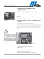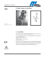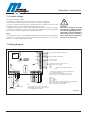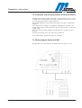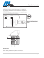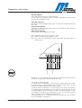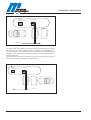
1
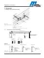
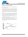
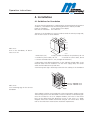
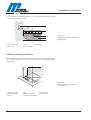
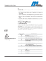
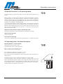
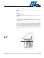
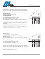
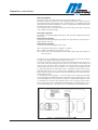
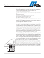
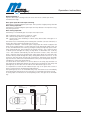
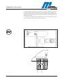
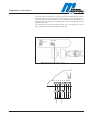
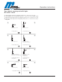
Operation Instructions Operating Instructions MAGSTOP Traffic Barrier MBE35/50 581E,5125/07.03 Operation instructions 1. 1.1 1.2 2. 2.1 2.2 2.3 2.4 2.5 2.6 2.7 3. 3.1 3.2 3.3 3.4 4. 4.1 4.2 4.3 5. 5.1 5.2 5.3 5.4 5.5 6. 7. 7.1 7.2 7.3 7.4 8. 9. 9.1 9.2 9.3 10. 10.1 10.2 10.3 581E,5125 Overview Example layout of barrier system Overview of system components Safety General Safety Information Intended use Symbols used in this Handbook Operational Safety Pedestrian Safety Technical Developments Warranty Functional description Functional description Ecoline barrier Drive unit functional description Spring functional description Limit switch functional description Installation Guidelines for foundation Installing the induction loops Barrier housing installation Mechanical installation and adjustments Gate arm- changing the length and installation Balancing springs- testing and changing the spring tension Adjusting the gate arm position Adjusting the limit switch Left handed and right handed versions and how to change them Main power connection Controller Control voltage Wiring diagram Installation and wiring connection of external devices Wiring diagram desk panel MKI Controller inputs Operating modes Short description Identical functions in all operating modes Operating modes functianal description Barrier and operation settings Barrier reset function after power is restored Signal, warning and traffic lights control dip switch 3 and 4 barrier close deplay timer Controller outputs K1 - K4 / dip switch 5,6,7,8 4 4 4 5 5 5 5 6 7 7 7 8 8 8 8 9 10 10 11 13 13 13 13 14 15 15 17 17 17 17 18 18 18 19 19 20 21 29 29 30 31 3 Operation instructions 11. 11.1 11.2 11.3 11.4 12. 13. 13.1 13.2 13.3 4 Trouble shooting Barrier does not funtion doesn't go up or down Barrier does not open or opens slowly/barrier comes down by itself Barrier arrier does not close or closes slowly/barrier opens by itself Barrier arm is not horizontally or vertically leveled Maintenance and service Addendum Technical data Technical support Spare parts and accessories 33 33 34 34 34 35 36 36 36 36 581E,5125 Operation instructions 1. Overview .0 ,2 m ... ca .1 m Ex i t 1.1 Example layout of barrier system m in 8 4 1 m m in.3 ax m .5 m 6 2 7 nc e 3 En tra Abb. S0001 Layout of barrier system S0001 1,7 safety loop 2,8 Magstop barrier (control unit in pillar) 3 presence loop 4. opening loop 6 MEC control pillar with plug-in module (e.g. for access control) 1.2 Overview of system components Sperrbreite max. 5 m Schranke MBE 35/50 barrier booms longer than 3.5 m require either a pendulum support or a supporting pillar Options induktion loop detektors 6 7 radio receiver 6 11 12 13 7 8 9 10 4 5 operating panel 14 MID 2 MID MDC 1 1 Options 3 4 MID1 1 MID2 MEC control pillar Abb. S0002 Overview of system components 581E,5125 2 2 2 3 MFS MKI control pillar MID I code card reader code key key-operated button / switch intercom token reader ticket dispenser ticket reader timer switch 1 or 3 channel code card reader code key key-operated button / switch intercom control pillar code card reader code key key-operated button / switch 5 Operation instructions 2. Safety 2.1 General safety information This MAGSTOP barrier system has been designed built and tested using state-ofthe-art technology and left our factory only after passing stringent safety and reliability criteria. Nevertheless the barrier system can represent a risk to persons and property if it is not installed and operated correctly. These operating instruc tions must therefore be read in their entirety and all safety information contai ned therein must be complied with. The manufacturer shall refuse to accept liability and shall withdraw warranty if this barrier system is used incorrectly or is used for a purpose for which it was not intended. 2.2 Intended use The MAGSTOP MBE 35/50 barriers are designed to control vehicular access and exits to car parks and access control applications. The MAGTRONIC control units have been specially designed for controlling Magnetic barriers. Any other use of these barrier systems is not permitted. Modifications or changes to the barrier or to the control modules are prohibited. Only original Magnetic spare parts and accessories shall be used. 2.3 Safety symbols used in this handbook The following symbols are used in this operating instruction to indicate potenti al risks and other safety information. Warning! Pedestrian safety is in danger whenever this symbol is displayed. This symbol is used in this manual to warn installer for potential harm. Please read these instructions very carefully. Caution! This symbol is used in this manual to designate those actions or states which represent a potential hazard to property and equipment. Please read these instructions very carefully. Note! This symbol is used in this manual to designate useful information for the ope rator. 6 581E,5125 Operation instructions 2.4 Operational Safety • A safe clearance distance of at least 2 ft (24 inch) must be provided between the tip of the barrier boom and the closest solid obstacle (building, wall, fence etc.). • Any activity in the entrance and exit lanes should be monitored to ensure a safe operation when opening or closing the barrier gates or to prevent altering or vandalism to the equipment from unauthorized persons. • The motion of the barrier boom must be directly observable by the person ope rating the barrier. • While the barrier boom is in motion no pedestrian and no vehicle shall be in the immediate vicinity of the barrier. • It is imperative to have pedestrian sidewalks be parallel to entrance and exit lanes or to have pedestrian walkways on the opposite sides of the facility away of vehi cle traffic. It is also necessary to enforce that pedestrian are using those walkways and do not enter or leave the parking facility on vehicle traffic lanes. • A main power switch or circuit breaker must be installed at the power source. • Pay attention to overhead power lines during the attachment or detachment of the gate arm. • Ensure that the workspace around the barrier is wide enough and that the instal ler has a safe ground to stand on. • The assembly and installation instructions must be complied with in their entire ty. Any alterations must have received prior confirmation from Magnetic Autocontrol GmbH. • The gate arm attachment kit is designed to withstand wind speeds up to 10 Beaufort (=500N/qm). Contact Magnetic if stronger winds are expected. • Barrier booms longer than 3.5m require either a pendulum support or a suppor ting pillar. • It is prohibited to install the barrier without proper mounting to the foundation. • Only certified and trained electrical technicians may perform any electrical con nections, wiring work or exchange of components. • The electrical wiring of the barrier must comply with the included drawings. · Main power to the barrier must be tested in accordance to local electrical code. • Before initial commissioning all electrical components including the external and internal wiring must be tested in accordance with the local electrical code. • Do not start the initial commissioning unless all safety equipment is installed and tested. • Before installing or maintaining the equipment the main power must be discon nected. • Disconnect all external opening or closing devises to prevent unintentional move ment of the barrier during service or maintenance work. • It is prohibited to perform any technical modification to the barrier. • Removing the front door and/or housing lid exposes powered electrical equip ment, tensioned springs, and lever system that can cause bodily harm if not handled correctly. • The motor surface temperature can exceed 80 ºC, touching the motor can cause skin burns. • During intentional or unintentional loss of power make sure to mechanically secure the barrier in its up position or remove the gate arm. If left in the up posi tion without power the arm can go down on its own (e.g. high wind gusts). 581E,5125 7 Operation instructions 2.5 Pedestrian Safety The barrier installation and operation must comply with this Installation and operation manual and all local accident prevention standards and codes. The MAGSTOP MBE 35/50 barriers are designed to control vehicular access and exits to car parks, car parking garages, access control applications, and highways. It is not designed for pedestrian usage of any kind. It is imperative to have pedestrian sidewalks be parallel to entrance and exit lanes or to have pedestrian walkways on the opposite sides of the facility away of vehi cle traffic. It is also necessary to enforce that pedestrian are using those walk ways and do not enter or leave the parking facility on vehicle traffic lanes. The Magnetic barriers come with two pictograms that warn pedestrian from using the vehicle lane. Any activity in the entrance and exit lanes should be monitored to ensure a safe operation when opening or closing the barrier gates or to prevent altering or vandalism to the equipment from unauthorized persons. The motion of the barrier boom must be directly observable by the person ope rating the barrier. While the barrier boom is in motion no pedestrian and no vehi cle shall be in the immediate vicinity of the barrier. Any operation of the barrier without observation and safety is prohibited. 2.6 Technical developments The manufacturer reserves the right to modify, without prior notice, the techni cal specifications in order to accommodate the latest technical developments. Magnetic Automation Corp. will provide information on the status of existing operating instructions and on any alterations and extensions that may be rele vant. 2.7 Warranty Magnetic provides a limited warranty on its barriers that covers all mechanical and electrical components, but excludes parts subject to wear and tear, for a period of two years from the date of first use or for a maximum of three years from the date on which the system was delivered provided that the operating instructions have been complied with, no unauthorized servicing of machine components has taken place, and that no mechanical damage to the machines is evident. Please refer to our Warranty Statement. 8 581E,5125 Operation instructions 3. Functional description 3.1 Functional description ECOLINE barrier The ECOLINE barriers come as RH (Right hand) or LH (left hand) version. The bar rier consists of the powder coated steel housing, drive unit and control panel with controller. The drive unit consists of the torque motor, lever system and spring unit. The included limit switch is only to sent the gate status to the controller it does not switch the torque motor in any way. The torque motor is always energized regardless if moving or in both end posi tions and therefore is always warm. The controller allows a manual and automatic operation of the barrier. The ope rating mode or control function can be set with DIP- and rotary switches. 3.2 Drive unit functional description The sinusoidal lever system transfers the motor torque to the output shaft. A bracket with two rubber end stops halt the gate movement in the end posi tion (UP or DOWN). This system always ensures that the vertical (UP) and hori zontal (DOWN) position is always kept throughout many years of operation. If, for any reasons the horizontal or vertical position of the arm is out of adjustment the output shaft must have slipped within the lever arm. See Chapter: Adjust gate arm position. During operation the motor torque and the sinusoidal lever system lock the gate arm in the up or down position. This prevents the ability to open or close the gate manually. In case of power failure the compressed energy in the rubber end stop pushes the lever arm out of its dead angle. Supported by the spring unit the arm can now be opened manually, without any tools or it can open automatically if the springs are adjusted for auto open on power failure. The weight of the arm is balanced by the spring unit. The motor is not strong enough to open or close the barrier without the support of the springs. If no gate arm is attached the motor is not strong enough to close the barrier. 3.3 Spring functional description To ensure a long and maintenance free lifetime of the barrier the gate arm must be balanced at a 45º angle. This means that the spring tension is holding the gate arm at the 45º position when the power is off. This is the most important adjustment of the drive unit system. Depending on arm length and accessories (signal lamps etc.) that are mounted on the gate arm more or less springs are necessary to balance the arm. The exact adjustment is can be done with the two set screws with which the spring tension can either be increased or decreased. As a result of the spring balance, a motor with low power consumption and less torque can be used to operate the barrier. The motor only needs to move and accelerate the lever system out of its dead position and the spring tension will pull up the arm are lower it smoothly. Automatically opening on power failure can be easily achieved by increasing the spring tension consequently it pulls up the gate arm in the event of power loss. Because of the limited spring tension the arm length and the attachment of Magnetic Accessories is restricted. If the maximum quantity and strength of the springs cannot balance the arm it will have a impact on the lifetime of the bar rier. Any add on to the barrier arm without consulting with Magnetic first will terminate the warranty. 8 581E,5125 9 Operation instructions 3.4 Limit switch functional description Ex factory a limit switch to disable the vehicle safety device (IN5) is connected to IN6. To disable the pedestrian safety device (IN4) a second limit switch (optional) must be connected in parallel to IN4. Vehicle and pedestrian safety devises such as inductive loops and or light beams can be connected to the controller. If the safety devise detected a vehicle or pedestrian while the barrier is in the up position or during closing the barrier will stay up or instantly reverse to the up position. The limit switch will disable the feature 15º (adjusted ex factory) before the barrier reaches the fully closed posi tion. Adjusting the limit switch to disable the safety device shortly before the arm reaches the end position achieves a long safety period while the arm is moving. Decreasing this angle will lower the safety but increase the tailgating prevention. The limit switch can easily be adjusted during installation by moving the limit switch cam. As soon the cam activates the limit switch it disables the safety devi ce and the barrier continues to go down regardless if a person or object is in the safety zone. The limit switch prevents the barrier from reopening when the bar rier is closed and a vehicle pulls up on or close to the safety zone. If a separate pedestrian and vehicle safety device is installed an additional limit switch for pedestrian safety is required. If there is no safety devices installed a jumper wire between IN4 to +24V and or IN5 to +24VDC are obligatory. Without the jumpers the barrier will not close. Please read chapter: "Input Functionality" for detailed input description. Prevision to install additional proximity or mechanical limit switches are made. To read more about how to adjust the limit switch please go to chapter: "Adjusting the limit switch" Opened 90˚ Safety angle adjustable between 80˚... 10˚ adjustment ex factory approx. 15 Position of barrier boom below the safety angle the limit switch (connected to IN4/IN6) disable the safety device and the barrier closed fully even there is a object in the area. Closed 0˚ 10 581E,5125 Operation instructions 4. Installation 4.1 Guidelines for Foundation To ensure that the equipment is solidly bolted to the ground under all operation conditions, a foundation with the following dimensions shall be provided: Depth of foundation: at least 800mm (frost-depth) Base area of foundation: 500 x 600 mm 15 5 5 15 19 0 50 0 The base of the foundation is 100 mm wider towards the vehicle passage side, than in other section of the foundation. 155 190 500 155 800 1 2 3 4 Abb. S0101 View of the foundation, all dimensions are in mm 5 600 S0101 1 Anchor bolts (4x) 2 Empty conduit for induction loop lead wire, dia. 29 3 Conduit for power cables, dia. 29 4 Conduit for control cables, dia.29 5 Concrete foundation (BH PC 250, Strength W=25N/mm≈) 19 0 Conduit pipes (with different diameters for low and high voltage cables as per Electrical code) must be installed to run the mains supply cable, the control cables and the induction loop lead wires. A reinforcing steel cage is absolutely essential for the stability of the foundation Abb. S0102 Steel reinforcing cage for the concrete foundation 5x Ø 8 440x440 St III 3x Ø 12 740x410 St III S0102 The foundation shall be constructed with at least W=25N/mm≈ grade concrete. The mounting surface must be leveled to insure a solid base for the barrier gate. Once the concrete has set to an adequate hardness, the holes for the anchor bolts can be drilled using the dimensions shown in Fig. S0101 as a guide. Magnetic Autocontrol GmbH recommends using Ø 3/8" anchor bolts. Please refer to the anchor bolt manufacturers installation requirements. 581E,5125 11 Operation instructions 4.2 Installing the Induction Loops This chapter describes how to install an inductive loop. The inductive loop below the gate arm shall only be uses for vehicle safety and closing of the barrier. As long the gate arm is up and a vehicle is on the induction loop the gate will remain up. If the vehicle leaves the detection zone the barrier can be closed or, in automatic mode, will close as soon the safety zone is cleared. The limit switch disables the safety device in the down position. In any case, the loop size, posi tion and geometry depend on the current installation. Note: Only metallic objects can be detected. The loop frequency change depends on the size and form of the to be monitored object (i.e. car) not on the material mass, which does not influence the loop. 300 1 300 3 m in .5 00 50 0 2 Abb. S0103 Example of how an induction loop is installed 1 Lane 2 Induction loop (size, geometry and length depend on installation require ments, arm length and vehicles) 3 Projection of the barrier arm on the lane at standard installation Following guidelines must be followed during installation of induction loops • The loop must be installed symmetrically centered to the gate arm. Please noti ce that the arm is mounted to the side of the barrier housing • The loop distance in front and behind the barrier arm must be at least 500 mm. • The distance between the end of the loop to the tip of the barrier arm and to the end of the roadway shall be around 300 mm. • When installing a automatic opening loop, these opening loop must be instal led direct in front of the safety loop. The distance between the safety loop and the opening loop must be between 0,2 m and 1 m max. • The loop must be installed so that it will not move when a vehicle passes over it. • If the roadway uses metal reinforcement you must keep a 50 mm distance between the reinforcement and the loop wire. Otherwise the reinforcement will degrease the loop sensitivity. • =The lead-in wire length should not exceed 15 m. It is a must to cut the leads to the proper length. Excessive long leads looped before it is wired to the detector will decrease the loop functionality. The loop lead-in wire must be twi sted about 20 times per meter up to the point where the wires connect to the detector. • Before sealing the loop you must measure the loop resistance and the loop insulation resistance to earth ground. The loop resistance must be lower than 2W. The loop insulation resistance to earth ground must be lower then 1 MW (see technical data regarding inductivity). If this is not the case the loop insula tion might be damaged. • Do not leave metal objects near the loop when measuring the resistance or inductivity. 12 581E,5125 Operation instructions Installation of induction loops in asphalt roads • Ready made loops in different sizes can be purchased from Magnetic (Type KAS 1-5). • Alternatively a loop can also be manufactured from a single 0,75-1,5 mm≈ cross section. The inductivity of the loop must range between 70 - 500 µH, which usually can be achieved with 3-5 wire turns. • The depth of the loop cut shall be at least 30 mm up to 70 mm deep (see Drawing S0104). The depth must be the same all around the cut out.. To les Warning! sen the stress and abrasion of the loop wire the 90° corners shall be cut at a When using an angle grinder, please 45° angle. follow the manufacturer´s safety instructions! • Please use caution when installing the loop wire in the cut out. Do not use any sharp objects to push or secure the wires in the cut out. • In addition you can cover the wire with fine sand. If you do so make sure that you leave a minimum distance of 25mm from top of sand to the road surface for the sealing compound. Caution!! The loop cable insulation must not be damaged during installation! The loop cable must be completely covered with sealing compound 1 150 300 2 Abb. S0104 Installing an induction loop in asphalt 25 30 50 3 4 5 6 S0104 1 barrier housing 2 cut out with sealing compound 4 fine sand 5 Loop wires 3 Asphalt 6 Foundation • After installing the loop wire run the lead wire through the existing conduit into the barrier housing. • The temperature of the sealing must be below the temperature of the wire insulation. Otherwise high temperature resistant wires must be used. Installation of induction loops in brick roads • If loops are being installed below brick roads you must purchase the loop wires from Magnetic (Type KAS1…KAS 5). • You must install the loop wires on sand and you also need to make sure that the wires will not move after the installation. 581E,5125 13 Operation instructions • You must keep a minimum distance of ca. 30 mm between the loop wire and the bricks (see drawing S0105) 1 150 300 2 30 3 4 5 Abb. S0105 Installing an induction loop under paving stones S0105 1 barrier housing 4 fine sand 2 brick 3 Loop wires 5 base material 4.3 Barrier housing installation Use the mounting kit that comes with each shipment to secure the housing to the foundation (see Fig. S0106). Make sure to level out the housing before secu ring the bolts. 1 2 3 4 5 6 7 8 S0106 1 barrier housing 4 small flat washers 7 U-rail 14 2 nut 5 large flat washers 8 concrete foundation Abb,S0106 Mounting the barrier housing to the foundation 3 lock washer 6 anchor bolt 581E,5125 Operation instructions 5. Mechanical installation and adjustments 5.1 Gate arm- Changing the length and installation Ones the gate arm is installed you must adjust the springs to balance the gate arm. Please note: • the overall arm length is not equal to the road width • Distance to support pillar • Distance from gate housing to curb edge Abb. F001 5.2 Balancing springs- Testing and changing the spring tension The functionality of the springs is explained in chapter 3.3. Magnetic does not adjust the spring balance prior to shipping. The correct spring tension is the installer's responsibility. You must adjust the springs after installing the gate arm and before turning the power on. The spring tension depends on the gate arm length. The barrier will only work correctly if the gate arm is perfectly bal anced. Warning! 4 When tensioned, the springs and the barrier boom exert considerable forces on the drive unit and there is thus a potential risk of injury. Any work on the drive unit must therefore be carried out only when the springs are not under tension and when the barrier boom has been secured or removed! 1 3 2 5 Abb. F002 1 2 3 4 5 gate arm spring tension adjustment screws with safety clips shaft clamp lever with socket head cap screws SW10 rubber end stop connecting rod with motor lever Following describes how to adjust the spring tension 1. Make sure that the power is turned off 2. Remove the safety clips on both spring tension adjustment screws 3. Manually move the gate arm to a 45º position 581E,5125 15 Operation instructions 4. Tighten or looses both screws evenly. The gate arm is balanced when it, by itself, remains at the 45º position. 5. Replace the safety clips If you attach anything (signs etc.) to the gate arm, shorten the arm for any rea son or exchange the gate arm with another gate arm you must readjust the spring tension again. Adjustment for automatic opening in the event of a power failure: To test this setting you must turn the power on, with the gate arm attached, close the barrier using the gate close command. When the arm is in the com plete down position turn the power off. The spring tension should now pull the gate arm up. The adjustment for automatic opening depends on arm length. The MBE35 can be adjusted for automatic opening up to a 3m the MBE50 up to a 5m gate arm 5.3 Adjusting the gate arm position Ex factory the gate arm is adjusted to be leveled in the horizontal position (down position) in respect to the housing. During installation it might be necessary to readjust the horizontal gate arm posi tion. The gate arm position can also be changed if vandalism occurred. The drive unit is designed to slip if extensive manual up or down force is applied to the gate arm. This prevents any physical damage to the drive unit shaft. The two allen screws (M12) that clamp the lever to the flange shaft are tightened with 65 Nm please make sure that you use the same torque to retighten the bolts. Warning: The gate arm adjustment must be done while power is applied therefore you must pay undivided attention when adjusting the gate arm position. Please make sure that no external device can operate the barrier while you are working on the adjustment. Do not reach inside the drive arms. The lever may not be moved laterally and must be parallel with the connecting rod and motor lever. 1. Make sure that no external switch, remote control, induction loop or any other device can operate the barrier while you perform the adjustment. If you are not sure if a device is activated or not simply mark all wires going to input IN1 and IN2 and disconnect them. 2. Close the barrier with a closing input. 3. Remove the housing lid. 4. Loosen, but do not remove, the M12 socket head cap screws that clamp the shaft lever to the shaft. The two screws shall still be tight enough to hold the arm in place but loose enough to be able to manually rotate the shaft while moving the gate arm up and down. 5. Manually move the gate arm to the desired position. 6. Tighten the two M12 socket head cap screws with 65Nm torque. 7. If you removed the inputs on IN1 and IN2 please reconnect them in the same way you removed them. 8. Replace housing lid. 16 581E,5125 Operation instructions 1 3 Abb. F003 1 gate arm 3 shaft clamp lever, allen srew M12 5.4 Adjusting the limit switch 6 8 Abb. F004 Limit switch with 1 cam and clamp 7 Abb. F004 6 imit switch 7 cam 8 clamp Ex factory the barrier comes with a limit switch connected to IN6. This limit switch (6) disables the safety device when the gate is in the down position. Ex factory the limit switch is adjusted to disable the safety device between 15º to 30º before the gate is fully closed. If you need to readjust the limit switch simply loosen the cam clamp (8) and rota te the plastic cam (7) to the desired position. Make sure that the cam is centered to the limit switch actuator and that the clamp does not hit the limit switch during a complete cycle of the barrier. Ausführung rechts Fahrbahn 5.5 Left handed and right handed versions and how to change them. Ausführung links 581E,5125 The MBE series can easily be changed in the field from RH to LH or vise versa. Please comply with the current standards of work safety. • Wear safety shoes • Turn of power to the barrier and make sure nobody can turn it back on while you are working on it. • Removing or installing the gate arm requires two people • Do not hold your hands inside the lever system 17 Operation instructions When changing from RH to LH or vise versa please follow these steps: 1. Remove housing lid and door 2. Turn power off and make sure nobody can turn it on while you are working on the barrier. 3. Move the gate arm manually to the up position 4. Remove the gate arm 5. Remove the springs 6. Loosen up but not remove the camp clamp and remove the limit switch pla stic cam 7. Loosen up, but don't remove, the two M12 socket head cap screws that clamp the shaft lever to the flange shaft. 8. Loosen up, but don't remove, the 4 (two on each bearing) set screws that hold the two flange bearing to the shaft. 9. Remove the rubber hole-plug opposite of the current flange location. 10. Pull the flange out of the unit while securing the shaft lever and the cam clamp from falling down. 11. Carefully insert the flange from the other side through the flange bearing, cam clamp, flange shaft and bearing on the opposite side. 12. Make sure that the distance between the housing and the inside of the flan ge is 40mm. 13. Ones the flange is in the correct position retighten the 4 (two on each bea ring) set screws using 5.5Nm torque. 14. Replace the rubber hole-plug 15. Slide the shaft lever along the shaft until the shaft lever and motor lever are parallel to each other. 16. Push the motor lever to the upper end stop. 17. Retighten the shaft lever using 65Nm torque. 18. Replace the springs. 19. Replace the barrier arm. 20. Turn the power on and send the gate to the closed position 21. Adjust the horizontal position of the barrier arm (see Chapter 5.3). 22. Reinstall the limit switch cam and adjust it to the correct position (see chap ter 5.4). 23. Close the housing door and replace the lid. Secure lever when removing 1 3 Bearing set screws 3 mm 40 5 Abb. F005 1 gate arm 3 shaft clamp lever 5 connecting rod with motor lever 18 581E,5125 Operation instructions 6. Main power connection Abb. F006 Power supply connection Abb. F006 7. Controller The ECOLINE controller has been specially designed for use with MBE 35and MBE 50 barrier gates. It cannot be used with any other barrier type. This controller enables the barrier to be operated manually or automatically. There are 11 standard functions to be selected for operating the barriers. These functions cover all standard applications. Integrated custom functions are: Control of signal - and warning lights Traffic light control Storage of applied opening inputs at IN1 Different reset functions The controller has 6 Inputs and 4 outputs. The motor is operated through wear and tear free TRIAC's. The operating mode and special functionality can be adjusted using the 16 position rotary switch and the 8 position DIP switch. The controller also comes with a manual reset button to reset the controller after any changes were made. Do not remove the plastic cover when operation the barrier. On the 230/240 V models the torque capacitor is built into the controller. 581E,5125 19 Operation instructions 7.1 Control voltage The control voltage is 24VDC. A T800mA (5 x 20mm) fuse (F2) protects the circuitry from overload. The controller provides 24VDc at max. 500mA for external equipment. In case of overload (electrical short, wrong connection, overload etc.) the F2 fuse disconnects the 24V circuit and the barrier goes out of order. In addition the main power input is also protected with a fuse F1 (F4A fast acting / 5 x 20mm). If a problem occurs this fuse will activate and disconnect the main power input to the controller to protect the controller and motor. Note: The 24V power supply is not regulated. Depending on the load it may fluctuate bet ween 24V - 30V. Pay attention to the main power input because it is still on when either F1 or F2 both fuses were activated. Warning! The control voltage is not stabilized and may stagger between 24 and 30 V depending on the connected external equipment. High voltage remain on parts of the control unit even when the fuses F1 or F2 are blown. F2 T800mA 7.2 Wiring diagram Transformer Operating Functions mode K4 Universal Error Output / traffic light * K3 Warning light / traffic light * K2 Pulse when gate opens / closes * K1 Feedback up - down / barrier closed * (Flashing in case of errors) 0V +24 V Total external load max. 500mA +24 V F1 F4AH Reset IN 1 2 3 4 5 6 +24V M barrier housing Voltage 230V 50/60Hz *) Function according to selected operating mode (see instruction manual) Relay contacts: load max. 24VDC/ 10 mA....1 A Relay contacts are shown in power - down state green/ yellow blue brown black 1 2 PE PE U V W Note: If no safety device is connected to IN4 and IN5 these inputs have to be connected to +24V (insulated wire strap). Inputs: IN 1 Open 1 * IN 2 Open 2 * IN 3 Close * IN 4 Safety device for detecting persons and limit switch IN 5 Safety device for detecting vehicles IN 6 Limit switch Safety for IN5 55255697 20 581E,5125 Operation instructions 7.3 Installation and wiring connection of external devices Available optional devices like loop detectors, radio receiver, relays etc. can be installed on the mounting plate or Din-Rail. Mounting brackets must be used to secure these devices from moving sideward. The mounting brackets come with the MID and MFS models if ordered from Magnetic. The controller power supply is not regulated. Depending on the load it can output 24VDC-30VDC. Please make sure that the external device is within the voltage range. Make sure that all external equipment combined do not exceed the max. of 500mA. Overload will activate the F2 fuse and turn the barrier off. Please read chapter "Trouble-shooting" for more help. 7.4 Wiring diagram desk panel MKI Wiring diagram for motor direction UP/DOWN with DIP switch 5 = OFF 581E,5125 21 Operation instructions 8. Controller Inputs The MBE controller has 6 digital inputs (IN = Input) for the control voltage +24 V. All inputs require a potential free contact. Activated inputs are displayed with a "RED" LED. Following is a description of the individual inputs: IN 1 Gate open input for operating modes 2,4 - B. Requires a potential free normal ly open contact from an access control device, push button etc. Higher priority than IN2 and IN3. As long as this input is made the gate will not close even then when there is a close signal at IN3. In the dynamic operating modes 5, 6, 9, and A this input starts the 30 or 60 second hold open time. During this time the gate will stay up until the time elap ses or closes immediately after a vehicle passed the safety closing loop (Mode 5B only).In the operating modes 8, 9, A, and B this input increments the vent count. IN 2 Opening loop input. Requires a potential free normally open contact from an inductive opening loop detector. The open hold time will not be set in any of the modes. IN 3 Gate close input. Requires a potential free a normally open contact. When this input is closed the gate will close as long as none of the safety inputs IN4 and IN5 or IN1 or In2 is activated. IN 4 Pedestrian safety input. Used for safety edges or photo beams. ( Not for induc tion loops). Requires a potential free normally closed contact. If the safety device detects a pedestrian while closing it will reopen the barrier and stay up for 5sec. If the gate is up while a pedestrian or object is detected at IN4 it will not close until the safe ty zone is cleared. This input can be disabled with an optional limit switch. If there is no pedestrian safety device connected a jumper wire between IN 4 and + 24VDC must be installed. IN 5 Vehicle safety/closing device input. Used for inductive loops and photo beams For example safety/closing inductive loop detector. Loop detectors do not detect pedestrians. Requires a potential free normally closed contact. If the safety device detects a vehicle while closing it will reopen the barrier and stay open until the vehicle lea ves the detection zone. If the gate is up while a vehicle or object is detected at IN5 it will not close until the safety zone is cleared. This input is disabled when the gate arm is in the down position by the down limit switch on IN6. If there is no vehicle safety device connected a jumper wire between IN 4 and + 24VDC must be installed. 22 581E,5125 Operation instructions IN 6 Limit switch input. This limit switch is installed EX factory in all MBE35 and 50 barriers. It has follo wing functionality: 1. Disabling of safety/closing devices connected to IN5 when the gate is in the down position. Ex factory the limit switch is adjusted to 10º-30º before com pletely closed. 2. The limit switch provides the controller logic with the information that the gate is in the down position. (see chapter 10.3 relays) 3. If the controller is setup for signal reset it uses the limit switch feedback to determine in what position the gate is when the main power returns after it was off. 4. If a warning signal is used on output relay K 3 the signal will stay on for 5sec. after the controller received the feedback from this limit switch that it is in the down position. 9. Operating Modes 9.1 Short description The MBE controller has 11 different operating modes which can be set using the 16 position rotary switch located on the controller. The selection is depending on if the barrier shall be operated manually or automatically and without or with safety devices. Please use a small flat head screw driver to set the switch to the desired position. After changing the operating mode a manual- or signal RESET is required when the barrier is in open position. ( See chapter 10.1) Warning! Turn the main power off before changing the modes or Dip switch settings. Rotary switch Position 0 1 2 3 4 5 6 7 8 9 A B C D E F 581E,5125 Short description No function Maintained contact function, Static Dead man function, Static IPulse control using one input (IN1), Static Pulse control using two inputs (IN1 & IN3) Static. Dynamic function with directional logic and open hold time 30sec. Dynamic function with directional logic and open hold time 60sec. Static with directional logic Pulse control with input counting on IN1 and count reset timer 30 sec. Dynamic with input counting on IN1 and count reset timer 30sec (=hold open timer) Same as Mode 9 but with count reset timer 60 seconds Static with input counting on IN1 and directional logic. No function No function No function No function 23 Operation instructions 9.2 Identical functions in all operating modes The safety inputs on IN4 and IN5 and limit switch input IN6 are identical in all modes. When the gate is closing and the pedestrian safety input IN4 detects a person the barrier returns to the fully up position. After IN4 is cleared the gate will remain in the open position for an additional 5 sec. until it closes. The pedestri an safety input on IN4 must be disabled in the down position with a limit switch (optional, not included in standard package). If the safety device detects a vehicle while closing it will reopen the barrier and stay open until the vehicle leaves the detection zone. If the gate is up while a vehicle or object is detected at IN5 it will not close until the safety zone is clea red. This input is disabled when the gate arm is in the down position by the down limit switch on IN6. Pedestrian safety and limit switch to disable input IN4: Pedestrian safety device to protect pedestrian when barrier is closing. Vehicle safety input IN5: Vehicle safety device. Limit switch at input IN6: Limit switch to disable vehicle safety device when barrier is in the down position. 9.3 Operating modes functional description Operating Mode 1 = factory default Maintained contact function, Static A potential free switch controls the barrier. Input 3 Contact closed = barrier closed". Input 3 Contact open = barrier open. IN4 = Pedestrian safety input (or jumper to +24 V) IN5 = Vehicle safety device (or jumper to +24 V) IN6 = Down limit switch disabling of vehicle safety device (IN5) when gate is in down position. IN 1 2 3 4 5 6 +24V close The barrier will only close if input IN4 and IN5 are not active (made). The only exception is if the 'Auto-reset" function is selected. In this case if the power failed and the vehicle stayed on the safety loop when the power was restored the loop detector will not detect the vehicle and the barrier will close. For the different ways of resetting the barrier after the power to the barrier is turned on please see chapter reset functions. 24 581E,5125 Operation instructions Operating Mode 2 Dead man function, Static Note: Do not use maintained switches only momentary switches are allowed in this mode. Input IN1: pulse to open the barrier. Input IN3: maintained signal until the barrier reached the down limit switch to close the barrier. IN4 = Pedestrian safety input (or jumper to +24 V) IN5 = Vehicle safety device (or jumper to +24 V) IN6 = Down limit switch disabling of vehicle safety device (IN5) when gate is in down position. The barrier will open or remain open after power up if no maintained close sig nal on IN3 is applied. The barrier only closes if the closing signal on IN3 is main tained until the barrier reaches the down limit switch. After reaching the limit switch the IN3 input can be released and the barrier will stay in the closed posi tion. If IN3 is released before the gate reaches the limit switch the boom will return to the up position. The barrier open input IN1 has a higher priority than the closing input IN3, the refore the barrier will open when a close input on IN3 and a open input on IN1 is made. 581E,5125 close open IN 1 2 3 4 5 6 +24V 25 Operation instructions Operating Mode 3 Pulse control using one input (IN1), Static Each input (pulse) on IN1 results in a change of direction (up/down). When the controller is setup for signal reset the controller can be reset with a momentary input on IN3 or a vehicle passing the safety closing device connected on IN5. First input: gate opens, second input: gate closes, third input: gate opens…a. s. o. Gate open input IN1: Open/Close using one momentary switch. Gate closing input IN3: This input resets the controller (Signal-reset) IN 1 2 3 4 5 6 +24V Every pulse signal (min. 200ms in length) on input IN1 will change the direction of the barrier. For example: First pulse IN1 opens barrier, Second pulse IN1 closes barrier, third pulse IN1 opens barrier ….etc. The barrier closes after a controller reset. For the different options on how to reset the controller please see chapter Reset function. In operating mode 3 the only function of IN3 is to reset the controller at start up. During normal operation in mode 3 IN3 has no function. open/close IN4 = Pedestrian safety input (or jumper to +24 V) IN5 = Vehicle safety device (or jumper to +24 V) IN6 = Down limit switch disabling of vehicle safety device (IN5) when gate is in down position. Operating Mode 4 Pulse control using two inputs (IN1 & IN3) Static. Signal on IN1 opens the barrier; signal on IN3 closes the barrier. Gate open input IN1: Momentary or maintained gate open input. This input has a higher priority than IN3 Gate closing input IN3: Momentary or maintained gate close input. IN 1 2 3 4 5 6 +24V 26 close The barrier closes immediately after resetting the controller (see chapter reset function) as long as the safety inputs IN4 and IN5 are not active. After that a pulse or maintained contact on IN1 opens the barrier and a pulse or maintained contact on IN3 closes the barrier. The barrier open input IN1 has a higher priori ty than the closing input IN3; therefore the barrier will open when a close input on IN3 and an open input on IN1 are made. open IN4 = Pedestrian safety input (or jumper to +24 V) IN5 = Vehicle safety device ( or jumper to + 24 V) IN6 = Down limit switch disabling of vehicle safety device (IN5) when gate is in down position. 581E,5125 Operation instructions Operating Mode 5 Dynamic function with directional logic and open hold time 30sec. The barrier opens by a pulse on IN1 or opening loop detector on IN2 and closes automatically after the hold open time is elapsed (30sec.), immediately after the safety device has been passed (IN5), or after a closing pulse has been given (IN3). The hold open time is fixed at 30sec. This program mode is used when automatic functioning of the gate is required. It also supports directional logic. Gate open input IN1: Momentary or maintained gate open input. This input has a higher priority than IN2 or IN3 Gate closing input IN2: Momentary or maintained gate open input from loop detector. This input has a higher priority than IN3 Gate closing input IN3: Momentary or maintained gate close input. IN4 = Pedestrian safety input (or jumper to +24VDC) IN5 = Vehicle safety device (or jumper to +24 V) IN6 = Down limit switch disabling of vehicle safety device (IN5) when gate is in down position. The barrier closes immediately after resetting the controller (see reset functions) as long as the safety inputs IN4 and IN5 are not active. Coming from direction 1 the barrier will be opened using input IN1. The activa tion of IN1 starts the hold open timer (30sec.) if this input is maintained it will stay on 30sec. until the input is released. As soon the input on IN1 is released the hold open timer starts to count down. If no vehicle passes through the safe ty closing loop before the hold open timer is elapsed the gate will close auto matically after the 30 sec. If a vehicle passes through the safety closing device before the timer elapses the barrier closes immediately after the vehicle that pas sed through the lane. If a vehicle drives from direction 1 it will first drive on the safety loop and then on the opening loop behind the barrier. The vehicle must activate both, the safe ty and opening loop, at the same time in order for the directional logic to work. It is imperative to install the two inductive loops only so far apart that at time of entry or exit both loops are detected simultaneously. The opening loop acts as an extended safety loop. The barrier closes immediately after leaving the ope 581E,5125 27 Operation instructions ning loop. The open hold time is erased after the barrier closed. If a vehicle travels from direction 2 it will first activate the opening loop. The bar rier opens and stays open as long the vehicle is present on the opening loop. If the vehicle backs up the barrier will close immediately after leaving the ope ning loop. If the vehicle drives forward the barrier closes immediately after lea ving the safety loop. It is imperative to install the two inductive loops only so far apart that at time of entry or exit both loops are detected simultaneously. Ticket Machine, Coin Acceptor etc. Barrier Gate Safety Loop Opening Loop Caution! Do not exchange the inputs IN1 and IN2 there are significant differences between those two inputs. Direction 2 safety device close open opening loop IN 1 2 3 4 5 6 +24V Operating Mode 6 Dynamic function with directional logic and open hold time 60sec. Same as operating mode 5 but hold open time is fixed at 60 seconds. 28 581E,5125 Operation instructions Operating Mode 7 Static with directional logic, no open hold timer For automatic barrier operation with for example card readers, remote controls, token reader, and induction loops. Gate open input IN1: Momentary or maintained gate open input. This input has a higher priority than IN2 or IN3 Gate closing input IN2: Momentary or maintained gate open input from loop detector. This input has a higher priority than IN3 Gate closing input IN3: Momentary or maintained gate close input. IIN4 = Pedestrian safety input (or jumper to +24V) IN5 = Vehicle safety device 8or jumper to +24V) IN6 = Down limit switch disabling of vehicle safety device (IN5) when gate is in down position. safety device close open opening loop IN 1 2 3 4 5 6 +24V The barrier closes immediately after resetting the controller (see reset functions) as long as the safety inputs IN4 and IN5 are not active. This mode has directional logic. If a vehicle travels from direction 1 a input on IN1 will open the barrier. The bar rier remains open as long the vehicle passes through the safety loop. If no vehi cle passes through the gate will remain open (static). If a vehicle drives from direction 1 it will first drive on the safety loop and then on the opening loop behind the barrier. The vehicle must activate both, the safe ty and opening loop, at the same time in order for the directional logic to work. It is imperative to install the two inductive loops only so far apart that at time of entry or exit both loops are detected simultaneously. The opening loop acts as an extended safety loop. The barrier closes immedia tely after leaving the opening loop. 581E,5125 29 Operation instructions Ticket Machine, Coin Acceptor etc. Opening Loop Safety Loop Barrier Gate Direction 1 If a vehicle travels from direction 2 it will first activate the opening loop. The bar rier opens and stays open as long the vehicle is present on the opening loop. If the vehicle backs up the barrier will close immediately after leaving the ope ning loop. If the vehicle drives forward the barrier closes immediately after lea ving the safety loop. It is imperative to install the two inductive loops only so far apart that at time of entry or exit both loops are detected simultaneously. Opening Loop Barrier Gate Safety Loop Ticket Machine, Coin Acceptor etc. Direction 2 30 581E,5125 Operation instructions Operating Mode 8 Pulse control with input counting and count reset timer 30 sec. No hold open timer. The barrier remains open until a vehicle has activated the safe ty device on IN5 and only closes after it has left the detection area. Gate open input IN1 with input counting: Momentary or maintained gate open input. This input has a higher priority than IN3 Gate closing input IN3: Momentary or maintained gate close input. Rest input count IN4 = Pedestrian safety input (or jumper to +24V) IN5 = Vehicle safety device (or jumper to +24V) IN6 = Down limit switch disabling of vehicle safety device (IN5) when gate is in down position. The barrier closes immediately after resetting the controller (see reset functions) as long as the safety inputs IN4 and IN5 are not active. Input counting and count reset timer Mode 8 supports the input count storage feature. It counts and stores every gate open signal at IN1 (up to 255) and decrements the count by passing the safety clo sing input on IN5. Every opening signal to IN1 increments the stored count by "one" and every time a vehicle passes through the safety closing device it decre ments the count by "one". The controller automatically sets the reset timer to 30sec. (max.). The reset timer is the timer that closes the gate after a gate open signal was received on IN1 and NO vehicle passed through the safety closing devi ce within the 30 sec. of the reset time. The reset timer will erase all stored counts. The barrier closes immediately after the last vehicle passed through the safety clo sing device which decrements the stored count to zero (0) or the reset time elap sed. In other words if five (5) cars sent an opening command to IN1 five (5) cars have to pass through the safety closing device for the barrier to close. If a momentary gate close signal is applied to IN3 it decrements the count by "one". If the closing input on IN3 is maintained the gate will close and stay clo sed, when the maintained contact is released before the reset timer elapsed and the stored count is more than one (1) the gate will go to the open position again waiting for the next vehicle to pass through the safety closing device.When the gate is closing and the pedestrian safety input IN4 detects a person the barrier returns to the fully up position. After IN4 is cleared the gate will remain in the open position for an additional 5 sec. until it closes without having to apply a new clo sing command. The pedestrian safety input on IN4 must be disabled in the down position with a limit switch (optional, not included in standard package). 581E,5125 close open IN 1 2 3 4 5 6 +24V When the gate is closing and the vehicle safety input IN5 receives an input the bar rier returns to the fully open position. As soon as the safety zone is cleared the bar rier closes immediately without having to apply a new closing command. When the barrier is closing and has already passed the switch point of the down limit switch, the safety feature is disabled and the gate will continue to close regardless if the safety device detects an object. Ex factory the limit switch is adjusted to disa ble the safety/closing device on IN5 15º before it reaches the fully closed position. 31 Operation instructions Operating Mode 9 Dynamic with input counting and count reset timer 30sec (=hold open timer) with directional logic. Gate open input IN1 with input counting: Momentary or maintained gate open input. This input has a higher priority than IN3 Gate closing input IN2: Momentary or maintained gate open input from loop detector. This input has a hig her priority than IN3 Gate closing input IN3: Momentary or maintained gate close input. Rest input count IN4 = Pedestrian safety input (or jumper to +24V) IN5 = Vehicle safety device (or jumper to +24V) IN6 = Down limit switch disabling of vehicle safety device (IN5) when gate is in down position. The barrier closes immediately after resetting the controller (see reset functions) as long as the safety inputs IN4 and IN5 are not active. Coming from direction 1 the barrier opens using input IN1. Mode 9 supports the input count storage feature. It counts and stores every gate open signal at IN1 (up to 255) and decrements the count by passing the safety closing loop input on IN5. Every opening signal to IN1 increments the stored count by "one" and every time a vehicle passes through the safety closing device it decrements the count by "one". The controller automatically sets the reset timer to 30sec. (max.). The reset timer is the timer that closes the gate after a gate open signal was received on IN1 and NO vehicle passed through the safety closing device within the 30 sec. of the reset time. The reset timer will erase all stored counts. The barrier closes immedia tely after the last vehicle that incremented the count passes through the safety clo sing device or if the reset timer elapses. If a vehicle drives from direction 1 it will first drive on the safety loop and then on the opening loop behind the barrier. The vehicle must activate both, the safety and opening loop, at the same time in order for the directional logic to work. It is imperative to install the two inductive loops only so far apart that at time of entry or exit both loops are detected simultaneously. The opening loop acts as an extended safety loop. The barrier closes immediately after leaving the opening loop. The reset timer is erased after the barrier closed. A closing input on IN3 erases all stored opening counts. The gate closes immedia tely. Opening Loop Barrier Gate Safety Loop Ticket Machine, Coin Acceptor etc. Direction 1 32 581E,5125 Operation instructions If a vehicle travels from direction 2 it will first activate the opening loop. The bar rier opens and stays open as long the vehicle is present on the opening loop. If the vehicle backs up the barrier will close immediately after leaving the ope ning loop. If the vehicle drives forward the barrier closes immediately after lea ving the safety loop. It is imperative to install the two inductive loops only so far apart that at time of entry or exit both loops are detected simultaneously. safety device close open 581E,5125 opening loop IN 1 2 3 4 5 6 +24V 33 Operation instructions Operating Mode A Same as Mode 9 but with count reset timer 60 seconds. Operating Mode B Static with input counting and directional logic. No hold open timer or reset timer. Gate open input IN1 with input counting: Momentary or maintained gate open input. This input has a higher priority than IN3 Gate closing input IN2: Momentary or maintained gate open input from loop detector. This input has a higher priority than IN3 Gate closing input IN3: Momentary or maintained gate close input. Rest input count IN4 = Pedestrian safety input (or jumper to +24VDC) IN5 = Vehicle safety device IN6 = Down limit switch disabling of vehicle safety device (IN5) when gate is in down position. The barrier closes immediately after resetting the controller (see reset functions) as long as the safety inputs IN4 and IN5 are not active. Coming from direction 1 the barrier opens using input IN1. Mode B supports the input count storage feature. It counts and stores every gate open signal at IN1 (up to 255) and decrements the count by passing the safety closing input on IN5. Every opening signal to IN1 increments the stored count by "one" and every time a vehicle passes through the safety closing device IN5 it decrements the count by "one". This mode does not have a reset timer. The barrier closes immediately after the last vehicle passed through the safety closing device which decrements the stored count to zero (0). In other words if five (5) cars sent an opening command to IN1 five (5) cars have to pass through the safety closing device for the barrier to close. In Mode B the gate will not time out to close. If for any reason the timer has to be reset to zero (0) apply a clo sing pulse to IN3. A momentary or maintained closing input on IN3 resets the stored count to zero (0) and closes the gate. If a vehicle drives from direction 1 it will first drive on the safety loop and then on the opening loop behind the barrier. The vehicle must activate both, the safe ty and opening loop, at the same time in order for the directional logic to work. It is imperative to install the two inductive loops only so far apart that at time of entry or exit both loops are detected simultaneously. The opening loop acts as an extended safety loop. The barrier closes immedia tely after leaving the opening loop. The reset timer is erased after the barrier clo sed. A closing input on IN3 erases all stored opening counts. The gate closes imme diately. Opening Loop Barrier Gate Safety Loop Ticket Machine, Coin Acceptor etc. Direction 1 34 581E,5125 Operation instructions If a vehicle travels from direction 2 it will first activate the opening loop. The bar rier opens and stays open as long the vehicle is present on the opening loop. If the vehicle backs up the barrier will close immediately after leaving the ope ning loop. If the vehicle drives forward the barrier closes immediately after lea ving the safety loop. It is imperative to install the two inductive loops only so far apart that at time of entry or exit both loops are detected simultaneously. safety device close open 581E,5125 opening loop IN 1 2 3 4 5 6 +24V 35 Operation instructions 10. Barrier and operation settings After setting the desired operating mode using the rotary switch you can set additional functions using the 8 position DIP switch. Factory default: DIP 1- 8 = OFF position Please use a small screw driver to set the Dip-switches. 1. Use DIP 1 and 2 to set the barrier reset function after power on. 2. Use DIP 3 and 4 to set the barrier close delay timer. 3. Choose the time table for the signal-/warning lights a-d 4. Choose the relay functions for K1 - K4. 5. Use DIP switch 5,6,7 and 8 to set the signal-/warning lights, traffic lights, and relay functions. 10.1 Barrier reset function after power is restored For safety reasons the factory default for DIP switch 1 and 2 is set to off. DIP 1 OFF OFF ON ON Function 2 OFF ON OFF ON Manueller Reset Manueller Reset Signalrest Auto reset DIP Switch 1 off: Manual reset After return of power the gate moves to the up position and a manual reset using the reset button is required DIP Switch 1 on: Signal- or Auto reset Activates the RESET functions of DIP switch 2. DIP Switch 2 off: Signal reset (only with DIP switch 1 in ON position) Signal reset. When the gate was in the up position before the power turned off, and still is after the power returned, the gate will stay up and only pressing the reset button at the controller, a down command, or passing of the safety closing device will reset the gate to go down. If the gate was in the fully closed position (down limit switch activated) before the power went off, and still is when the power returned, the gate will remain in the down position 36 581E,5125 Operation instructions DIP Switch 2 on: Auto reset (only with DIP switch 1 in ON position) Auto reset. The gate will close immediately after the power is restored as long there is no vehicle or pedestrian (if IN4 is used) in the detection zone. Warning! If the power was restored while a vehicle was on the induction safety loop any loop detector will read this vehicle as part of the loop and will not detect the vehicle when the gate comes down. This will cause the gate to hit the vehicle! The adjustment Auto reset is not recommended. 10.2 Signal, Warning and traffic lights control DIP switch 3 and 4 barrier close delay timer Factory default: DIP 3 and 4 = OFF position Controlled relays K3 and K4 (see chapter 10.3) DIP 3 OFF OFF ON ON Signal and warning Barrier close delay time 4 OFF NONE ON 2 sec. OFF 5 sec. ON 9 sec. lights functions adjustable using DIP switch 7 and 8 DIP switch 3 and 4 are used to set the barrier close delay timer. This timer is used to activate signal and warning lights before the barrier closes. If a clo sing input on IN3 or a vehicle passes the safety closing zone the barrier will close after the close delay timer elapses. If not closing delay is selected the barrier closes immediately. If a closing delay timer is activated it will first acti vate a output relay that controls the warning lights and closes after the timer elapses. For exact functionality of this feature please see chapter "Time table for war ning and traffic lights". 581E,5125 37 Operation instructions Time table for warning and traffic lights DIP switch 7 and 8 a) b) c) d) Warning lights without closing delay timer, DIP 7 = OFF / DIP 3,4 = OFF Warning lights with closing delay timer, DIP 7 = OFF / DIP 3,4 according to table Red/Green traffic light without closing delay timer, DIP 7,8 = ON / DIP 3,4 = OFF Red/Green traffic light with closing delay timer, DIP 7,8 = ON / DIP 3,4 accor ding table 1 2 Barrier gate is closed Barrier gate opens => Signal light is off => Signal light stays off 3 4 Barrier gate is open Barrier gate is open Vehicle enters safety loop => Signal light stays off => Signal light stays off 5 7 38 safety angle Vehicle exits safety loop Barrier gate closes immediately Boom position reaches safety angle Delay time starts => Signal light is turned on => Relais K3 on => Signal light stays on => Relais K3 on 6 8 safety angle Delay time expires Barrier gate is closed => Signal light is turned off => Signal light stays off 581E,5125 Operation instructions b)Signal Light with Lead Time DIP7 = OFF DIP 3/4 see chapter 10.2 1 2 Barrier gate is closed Barrier gate opens => Signal light is off => Signal light is stays off 3 4 Barrier gate is open Barrier gate is open Vehicle enters safety loop => Signal light is stays off => Signal light is stays off 5 7 581E,5125 safety angle Vehicle exits safety loop Barrier gate closed after lead time expires Boom position reaches safety angle Tailing time starts => Signal light is turned on and stays on during load time => Relais K3 on => Signal light stays on => Relais K3 on 6 8 safety angle Tailing time expires Barrier gate is closed => Signal light is turned off => Signal light stays off 39 Operation instructions c) Traffic Light without Lead Time DIP 7/8 = ON DIP 3/4 = OFF 1 safety angle Barrier gate is closed Barrier gate opens Boom position is still below the safety angle =>Relais K3/K4 = on =>Relais K3/K4 = on =>Traffic light is red =>Traffic light stays red 3 2 4 safety angle Barrier gate opens boom position is above the safety angle Barrier gate is open =>Relais K3/K4 = off =>Relais K3/K4 = off =>Traffic light turns green (red is off) =>Traffic light stays green (red is off) 5 6 Barrier gate is open Vehicle enters safety loop Vehicle exits safety loop Barrei gate closed immediately =>Relais K3/K4 = off =>Relais K3/K4 = on =>Traffic light stays green (red is off) =>Traffic light turns red 7 Barrier gate is closed =>Relais K3/K4 = on =>Traffic light stays red 40 581E,5125 Operation instructions d) Traffic Light with Lead Time DIP7/8 = ON DIP 3/4 see chapter 10.2 1 safety angle Barrier gate is closed Barrier gate is opens Bomm position is still below the safety angle =>Relais K3/K4 = on =>Relais K3/K4 = on =>Traffic light is red =>Traffic light stays red 3 2 4 safety angle Barrier gate opens Bomm position is above the safety angle Barrier gate is open =>Relais K3/K4 = off =>Relais K3/K4 = off =>Traffic light turns green (red is off) =>Traffic light stays green (red is off) 5 6 Barrier gate is opens Vehicle enters safety loop =>Relais K3/K4 = off =>Traffic light stays green (red is off) Vehicle exits safety loop Lead time starts Barrier gate stays open =>Relais K3/K4 = on =>Traffic light turns red 7 8 Barrier gate closes after lead time expires =>Relais K3/K4 = on =>Traffic light stays red 581E,5125 Barrier gate is closes =>Relais K3/K4 = on =>Traffic light stays red 41 Operation instructions 10.3 Controller outputs K1 - K4 / DIP switch 5,6,7,8 The MBE controller has 4 relay outputs (K* = Output). The output relay contacts are rated for 24 V DC/ 1A. Factory default: DIP 5,6,7, and 8 = OFF DIP 5 OFF ON 6 OFF ON 7 OFF ON 8 OFF ON Relay function K1 Motor drive indication. Flashing when error or reset expected Gate closed indication. Relay is active when limit SW active. K2 Pulse when vehicle passes through safety closing zone Pulse when barrier opens, for sliding or roll doors K3 Signal- Warning lights (Close delay timer DIP 3,4) see chapter 10.2 Traffic light control (Close delay timer DIP 3,4) see chapter 10.2 K4 Universal error output Additional traffic light control like K3 (Close delay timer DIP 3,4) All four relay outputs (K1-K4) are Form C relays with a potential free (dry) output. Each relay has two selectable functions (see table above) that remain the same in all operating modes. Each relay has a red LED indicating light that is on when the relay is active. Output K 1: Motor drive direction, reset expected, error or barrier closed indication Depending on DIP switch 5 settings: DIP switch 5 in off position: Motor drive indication. Relay is active as soon as gate starts to come down. DIP switch 5 in ON position: Gate closed indication. Relay is active as soon as the gate is in full closed position, depending on limit switch settings. This relay output, independent of the DIP switch setting, will cycle between on and off when a gate failure occurred or right after the power is turned on. In this case pushing the RESET button will get the controller in the operating mode. Output K 2: Pulse when passing safety closing zone or slide-roll door pulse Depending on DIP-switch 6 settings. DIP switch 6 in off position: 500ms pulse signal when barrier is open and a vehi cle passed through the safety/closing device connected to IN5. DIP switch 6 in on position: 500ms pulse signal when the controller received in input on IN1 gate open for roll or sliding doors. 42 581E,5125 Operation instructions Output K 3: Warning or traffic lights Depending on DIP-switch 7 settings. DIP switch 7 in off position: This output is used to turn warning signals (lights or horns) on prior to closing the barrier. For example turning on a red light to alarm people that the gate will close soon. The light will turn off after 5 seconds after the gate closed. DIP switch 7 in on position: This output is used to turn warning signals (lights or horns) on prior to closing the barrier. For example turning on a red light to alarm people that the gate will close soon. The light will remain on as long as the gate is in the down position. Output K 4: Universal error or traffic lights Depending on DIP-switch 8 settings. DIP switch 8 in off position: Universal error output. If red LED is ON = no error. Gate failures reported are: 1. run time error in case the end limit switch is not activated when the gate is in the down position 2. controller is waiting for a manual or signal reset 3. pedestrian safety input IN4 is occupied longer than 3 minutes (e.g. dirty light beam) 4. vehicle safety input IN5 is occupied longer than 3 minutes (e.g. detector fai lure) 5. in case of a power failure of the 24V or 5V supply. DIP switch 8 in ON position: same functionality as K3 (DIP switch 7 on). 581E,5125 43 Operation instructions 11. Trouble shooting 11.1 Barrier does not function. Doesn't go up or down. Error After power on barrier is not functio ning, no LED lights are on Possible cause Main power is not connected Solution Wrong connection Blown fuse Main safety switch off F1 safety switch off Main switch off Main power is on but still no function Fuses F1 and/or F2 on control board Attention:Turn power off and make sure and all LED's are off are blown. Overload or electrical short. nobody can turn it back on. Replace Max. load for external equipment is fuses if necessary. Check the external 24VDC @ 500mA. equipment for current max. Current. Barrier does not open or close but LED's are on LED of relay K1 is blinking Missing reset Wrong rotary switch or DIP switch settings Wiring is wrong Universal error Barrier arm is not attached. Barrier does not operate after reset. Barrier does not close. Barrier does not close. Barrier does not Wrong operating mode open or close as desired Wrong DIP switch settings. External devices (loop detector, card reader etc.) connected wrong. Limit switch out of adjustment Barrier does not close Loop detector does not see loop. Loops are cross talking. Barrier does not close Maintained input on IN1. Missing wire bridge from +24VDC to IN4 or IN5 if no safety device is instal led. Light beam dirty or out of adjustment. Barrier does not close or open. Controller or motor wiring incorrect. Controller or motor defect. Motor thermal switch activated. Barrier does not close or open. Limit switch wiring incorrect or limit switch is out of adjustment. 44 Reset controller (manually or signal). Check and set Dip switch 1 and 2 and rotary switch settings Attach barrier arm and adjust the springs. Check your operating mode and DIP switch settings. Check loop detector and loops. Set different loop frequencies to prevent cross talking. Check inputs.Clean or readjust light beam. Check wiring. Check motor and controller. Let motor cool down and try again.Be careful! Motor is hot! Check limit switch wiring. Readjust limit switch plastic cam. 581E,5125 Operation instructions 11.2 Barrier does not open or opens slowly/ Barrier comes down by itself Error Barrier does not open or closes on its own. Barrier arm closes on its own without power if not balanced at a 45º angle. Possible cause Solution Barrier arm too heavy. Adjust the springs so the arm is balan Wrong spring adjustment. ced at a 45º angle when power is off. Springs too weak. Additional mounted objects on barrier Adjust spring balance. arm like signs, lights, etc. Add springs. Wrong barrier arm. Check barrier model and barrier arm Damaged spring. for correct model. Barrier opens slowly but closes fast and Wrong spring adjustment. slams into the down position. Barrier arm too heavy or too long Check spring adjustment.See Chapter 5.2 Balancing springsTesting and changing the spring ten sion 11.3 Barrier does not close or closes slowly/ Barrier opens by itself Error Barrier does not close or opens on its own. Barrier arm is not balanced at a 45º angle and opens by itself (if adjusted for auto open on power failure the adjustment is correct). Possible cause Barrier arm too light. Spring adjustment incorrect. Spring adjustment too strong. Barrier arm was shortened but the springs weren't readjusted. Wrong barrier arm. Barrier closes slowly but opens fast and Wrong spring adjustment. slams into up position. Barrier arm too light or too short. Solution Adjust the springs so the arm is balan ced at a 45º angle when power is off. Adjust spring balance. Remove springs. Check barrier model and barrier arm for correct model. Check spring adjustment. See Chapter 5.2 Balancing springsTesting and changing the spring ten sion 11.4 Barrier arm is not horizontally or vertically leveled Error Possible cause Solution Barrier is not leveled in the up or down Flange shaft slipped inside the shaft Correct barrier arm position. position. lever. Torque down the bolts using 65Nm torTorque of the shaft lever screw is below que. 65Nm. See chapter 5.3 Adjusting the gate arm Vandalism.Barrier arm was manually position forced up or down. 581E,5125 45 Operation instructions 12. Maintenance and service The ECOLINE barrier gates are designed for a long lifetime with only a minimum of maintenance required. The motor itself is maintenance free. To guarantee the greatest available equipment uptime and maximize the lifetime of the barriers please follow the prescribed maintenance schedules. If it becomes necessary to exchange parts, you must use original spare parts from magnetic. You must obey the safety requirements when working on the barrier. A) Check the spring adjustments and arm position. B) Check the rubber end stops and exchange them if necessary. C) Inspect the housing inside and batch up paint damages. D) Inspect the barrier arm for physical damage and check if the barrier arm attachment kit is used properly and all parts are in place and tight. E) Inspect for proper attachment of all safety related signage such as Gate Cabinet and barrier arm safety sticker. F) Check barrier operation. G) Inspect and test all safety devices such as light beams and inductive loops. H) Inspect and test the limit switch and cam position. Every 6 months Every 6 months Every 6 months Every 6 months Every 6 months Every 6 months Every 6 months Every 6 months If the barrier is not used for a long period of time after installation move it to the up position and remove the gate arm. If at all possible leave the power on and maintain the up command on IN1. This will provide the maximum protection against corrosion. Make sure to test all safety devices when reinitiating the barrier operation. 46 581E,5125 Operation instructions 13. Addendum 13.1 Technical Data ECOLINE Model Barrier inclusive controller Maximum arm length Pendulum support/post Opening time Closing time Voltage Frequency Max. Current draw Power consumption Housing size Length x Width x Height Weight without packaging Weight with packaging Weight with packaging And arm Protection Temperature range Controller Control voltage Power consumption Power output Max. Output current Main Fuse F1 Secondary Fuse F2 Inputs, 6 Relay output potential free, 4 Max. contact load Operating capacitor MBE35*- MBE50*- sec sec V Hz A W 3500 3,0 3,6 230 50 0,35 85 5000 necessary 6,3 7,5 230 50 0,35 85 mm Kg Kg kg 300 x 350 x 1040 56 68 72 300 x 350 x 1040 56 68 75 IP °C 54 -25....50 54 -25....50 V / DC W V / DC mA V / mA 24 15 24, nicht stabil. 500 F4A H T800mA 24 / 10 24 15 24 , nicht stabil. 500 F4A H T800mA 24 / 10 V DC/ A µF 24 /0,01...1 2 24 /0,01...1 2 mm 13.2 Technical Support Please contact our authorized dealer if you experience problems during opera tion. Please make sure that you have the barrier model and serial number ready when calling. 13.3 Spare parts and accessories Spare parts and optional accessories can be viewed in a separate catalogue which can be requested from our authorized dealers or from Magnetic. © 2003 by Magnetic Autocontrol GmbH, 79650 Schopfheim 581E,5125 47 Magnetic Autocontrol GmbH Grienmatt 20 D-79650 Schopfheim Telefon: Telefax: e-mail: http: 48 +49 7622 / 695-5 +49 7622 / 695- 602 [email protected] www.ac-magnetic.com 581E,5125