1
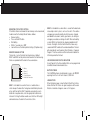
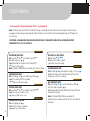
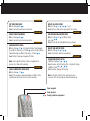
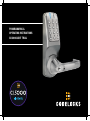
PROGRAMMING &
OPERATING INSTRUCTIONS
CL5000 AUDIT TRAIL
1
CODES AND OPERATION
CODES
OPERATING INSTRUCTIONS
• The factory set Master Code is #1234.
This should be changed immediately after installation (see
Program 10).
• The Master Code and optional Sub-Master Code always start
with the # prefix. This puts the lock into Programming Mode.
• When the Master or Sub-Master Code is entered 3 times
consecutively without performing a programming function, a penalty time of 10 seconds is activated.
• The length of the Master Code determines the length of the
User Codes and the Sub-Master Code.
• If the Master Code is changed to another of the same length
then the Sub-Master and all User Codes will be retained.
• If the Master Code is changed to one of a different length
then the Sub-Master and all User Codes will be deleted.
• Codes may be 4, 5 or 6 digits long. The lock memory will
store 989 different User Codes, each identified by a User
Code ID - 001-989.
• The lock memory can store 10 different One Time User
Codes. Each One Time User Code is identified by a One
Time User Code ID - 990 to 999.
• If Program 16 is activated, User Codes can bet set
individually or as a group using Program 17 to enable the
lock to be opened only at specified times.
• When in Programming Mode a Program Code must be
entered within 5 seconds, otherwise the Red LED will flash
and BEEP and the lock will revert to normal.
• If a programming mistake is made wait 5 seconds, the Red
LED will flash and BEEP and the lock will revert to normal.
• A new code will be rejected if it is already in the memory.
The CL5000AT lock has a 12 button keypad including ✱ and # buttons.
AUDIT TRAIL FUNCTION
The CL5000AT has the ability to provide audit
information of lock activity; time lock opened, User Code
used etc. Once activated (Program 16) the same software
allows for easy programming of locks via a USB Stick
from a PC to the lock and from the lock back to the PC.
Multiple locks can be programmed in this way if required.
UNLOCK TIME
The factory pre-set UNLOCK time is 4 seconds. This may
be changed – (see Program 06).
PENALTY TIME
Entering 3 incorrect codes will cause the lock to suspend
activity for a penalty time of 10 seconds.
KEY OVER-RIDE
Turn the key clockwise 90º and depress the lever handle
to open the door.
CODE FREE MODE
Using the Master or the Sub-Master Code, Programs 08
and 09 will put the lock into, and out of, Code Free Mode.
In Code Free Mode battery power is not being used. If
Master and Sub-Master Codes cannot be issued for this
purpose it is possible to use the Key-in-Lever to put the
lock into Code Free Mode. This requires that the cylinder
tailpiece be changed according to the instruction on
pages 4 and 5.
REVERTING TO FACTORY SETTING
If the Master Code is not known the lock memory can be cleared and
made to revert to the factory Master Code as follows:
• Remove battery
• Press and hold ‘0’ button
• Refit battery
• Within 7 seconds press ‘000’
• Lock will be reset to factory default settings (AT option only).
REMOTE RELEASE OPTION
The lock has 2 sets of terminals for remote release, labelled REM 1 and REM 2 on the printed circuit board in the front housing.
Cables are provided with the lock for these connections.
1.
2.
3.
4.
5.
Battery
Remote 1
Remote 2
Clutch / Actuator
Data Cable Connector
REM 1 is intended for use when there is a need to allow a
visitor to open the door after having been identified by intercom
or by sight from within. REM 1 would be connected to a push
button on a reception desk, or to the appropriate button on an
intercom. Pushing the button would cause the Blue LED to light
and would release the lock for the normal set time.
REM 2 is intended for use when there is a need for the door to be
released by an alarm system, such as a fire alarm. This enables
emergency personnel to rapidly check that no one is trapped,
overlooked in classrooms, wards, guest rooms, etc. during an
emergency evacuation, or during a fire drill. When activated by
an alarm REM 2 will maintain the unlocked condition for 30
minutes. During this time the Red LED will flash once every
second and BEEP to indicate the unlocked condition. The lock
will automatically revert to normal after 30 minutes. If required
Program 11 can be used to revert the lock to normal before the
30 minute period has finished.
LOCKED/UNLOCKED STATUS INDICATION
Using Program 15 the Blue and Red LEDs can be programmed
to indicate locked and unlocked status.
BATTERY POWER
The CL5000 Electronic should provide in excess of 200,000
openings from the 4 x AA cells rated at 2,900 mAh.
LOW BATTERY
When the battery power is low the Red LED will flash 5 times
before the Blue LED flashes to signal acceptance of the code.
Batteries should be changed as soon as this happens.
3
CYLINDER REMOVAL
REMOVAL OF FRONT-LOAD CYLINDERS TO CHANGE KEY BYPASS FUNCTION, TO REPIN CYLINDERS,
OR TO REPLACE WITH CYLINDERS BY A DIFFERENT MANUFACTURER*
1
1. Remove handle and cylinder cover.
2. T urn key 90º clockwise and remove cylinder from boss.
*If intending to use a cylinder by a different manufacturer it is advisable to confirm beforehand that the new cylinder will fit the boss. Note that the CL5000 uses a 6 pin screw-
cap cylinder.
CHANGING KEY BYPASS FUNCTIONS
A
2
B
A - Storeroom function
Tailpiece allows key to turn 90º clockwise to enable handle to
retract the latch - this is the factory fitted function.
B - Classroom function
Tailpiece allows key to turn 90º clockwise and be removed leaving
the handle engaged in Code Free Mode.
Code Free Mode is cancelled by turning key 90º anti-clockwise.
4
THESE TAILPIECES WILL FIT MOST SCREW-CAP
CYLINDERS FROM OTHER MANUFACTURERS
3
4
3.
Remove key from cylinder. Hold down the control pin in the
end of the cylinder and unscrew the cap.
4.
Replace the tailpiece, hold down the control pin and screw
the cap fully on without tightening. Ensure control pin
projects to lock the cap.
5.
Test the key operation. If the key is difficult to insert or tight
when turning, then the cap maybe too tight. Loosen the cap
one notch at a time and try the key again. If the key inserts
and turns OK, but is difficult to remove, then the cap may be
too loose. Tighten up the cap one notch at a time. Adjust the
cap until the key inserts, turns and removes easily.
CAUTION! DO NOT INSERT THE KEY IN THE CYLINDER
ONCE YOU HAVE REMOVED THE SCREW-CAP
5-6
6.
With key turned 90º clockwise replace cylinder, cylinder
cover and handle.
5
PROGRAMMING
* First change the factory Master Code #1234 – see Program 10.
Note: The Master Code and Sub-Master Code MUST always start with #. All codes must be the same length as the Master Code.
A or in the Key Sequence below indicates LED illumination. To use Audit Trail Function and programming via PC Program 16 must be active.
• •
IF ENTERED, A SUB-MASTER CODE CAN BE USED INSTEAD OF THE MASTER CODE FOR ALL PROGRAMS EXCEPT
PROGRAMS 10,12,14,16,17,18 AND 19.
PROGRAM 01
ENTER NEW USER CODE
#Master Code
01
User Code ID (e.g. 001)
New Code (e.g. 4321)
Result: New code 4321 entered at User Code ID 001.
( when user enters code)
Note: ID positions 990 to 999 are reserved for One-Time User Codes.
• •
••
•
•
PROGRAM 02
SUSPEND USER CODE
#Master Code
02
User Code ID (e.g. 001)
Result: User Code at ID 001 suspended.
(
when user 001 enters code).
• •
••
PROGRAM 03
RESTORE USER CODE
#Master Code
03
User Code ID (e.g. 001)
Result: User Code at ID 001 restored.
( when user 001 enters code).
• •
•
• ••
••
••
PROGRAM 04
SUSPEND ALL USER CODE
#Master Code
04
Result: All User Codes suspended.
(
when user enters code).
6
••
PROGRAM 05
RESTORE ALL USER CODES
#Master Code
05
Result: All User Codes restored.
( when all users enter code).
• ••
•
PROGRAM 06
CHANGE UNLOCK TIME
#Master Code 06 enter open time (range 2 - 9 secs)
Result: After code entry the lock will unlock for the set time.
(Factory pre-set time is 4 seconds).
• •
••
PROGRAM 07
ONE-TIME USER CODE
#Master Code
07
One Time Code ID (e.g. 990)
One-Time Code (e.g. 5555)
Result: Code 5555 in position 990 will work once and then be
removed from memory.
• •
••
•
Note: ID Positions 990 to 999 are reserved for this program function, allowing up to 10 One-Time User Codes to be entered.
PROGRAM 08
PROGRAM 12
SET CODE FREE MODE
#Master Code 08
Result: Lock will be continuously unlocked.
DELETE ALL USER CODES
#Master Code
12
12
(7 secs)
Result: All User Codes will be cleared from the memory.
• ••
• • ••
PROGRAM 09
PROGRAM 13
CANCEL CODE FREE MODE
#Master Code 09
Result: Lock will revert to normal operation.
ADD/CHANGE SUB-MASTER CODE
#Master Code
13
Sub-Master Code (e.g. 2468)
Result: A Sub-Master Code #2468 has been entered.
• ••
• •
••
PROGRAM 10
CHANGE MASTER CODE *
#Master Code
10
Enter length of Master Code followed by new Master Code (e.g. 6, 123456)
confirm length of Master
Code followed by new Master Code (e.g. 6, 123456)
Result: Master Code now changed to #123456.
• •
•
PROGRAM 14
DELETE SUB-MASTER CODE
#Master Code
14
14
Result: Sub-Master Code has been deleted.
• • ••
••
PROGRAM 15
LOCKED/UNLOCKED STATUS
1. #Master Code
15
1
Result: Locked - No LED flashing (this is the default setting).
2. #Master Code
15
2
Result: Locked - Red
LED flashing.
• • ••
• • ••
•
Note: If the length of the Master Code is changed then all previous User Codes will be deleted.
PROGRAM 11
CANCEL EMERGENCY OPEN MODE
#Master Code
11
Result: The emergency unlocked condition via REM 2 will be
cancelled and the lock will revert to normal operation.
• ••
Note: If activated, LEDs will flash continuously every 5 seconds. LEDs will not indicate unlocked mode by key.
Code accepted
Code rejected
Code(s) valid but suspended
•• 7
PROGRAMMING
3
ACTIVATE AUDIT TRAIL FUNCTION
1. Set date, time, daylight saving and Door ID on lock. See program 16, page 9.
2. Insert Codelocks USB Stick into PC. Following prompts, install
data management software (DMS). Activate Codelocks USB Stick by clicking on the “Tools”menu
and select “Activate USB”
Close down DMS and remove USB Stick from PC
3. Insert USB Stick into lock USB port.
4. Enter: #Master Code
19
1
followed by
(flash for 35 seconds). Audible BEEP will signify process complete.
5. Remove USB from lock and insert into PC USB port.
6. Open DMS and click on “Open USB” button.
7. Click on data file in left hand column. The data file will match the Door ID set in 1 above.
8. Following on screen prompt, enter Master Code for lock. Note: No # prefix required.
9. “Main Settings” and “User ID Setting” can now be modified or added by clicking on either settings tab to make changes required.
10. Once changes have been made, click “Save to USB” button at bottom of screen.
11. Remove USB Stick from PC and insert into lock USB port.
12.Enter: #Master Code
19
2
followed by (flash
for 10 seconds)
(flash for 35 seconds). Audible BEEP will signify process complete and changes uploaded to lock.
Note: Master Code used in Point 12 must be Master Code installed
on lock. If Master Code has been changed, it will only be active after
successful data upload to lock.
•
•
• • ••
•
8
• • ••
•
Note 1: Audit information and program settings can be
uploaded/downloaded to and from the PC and lock via the
activated USB Stick using Program 19.
Note 2: When Program 16 is active, the Audit Trail
Function is automatically enable for all previously installed
and new User Codes.
Note 3: Programs 17, 18 and 19 will not work until
Program 16 is active.
Note 4: If daylight saving (DST) is enabled, system will
auto-adjust time. If daylight saving is not required, enter
0000 in the start and end DST section in Program 16.
If the start date and end date of daylight saving should
change in subsequent years, adjust your settings in the
Data Management Software (DMS). For assistance with DST, go to:
www.codelocks.com/help/dst
Note 5: Should battery power fail for more than 24 hours,
Program 16 will need to be re-entered to reset the clock
time. All program features will be retained.
•
ONLINE HELP
Additional information is available at:
www.codelocks.com/help/audit
PROGRAM 16
SET A VALID CODE ACTIVE PERIOD
SET DATE AND TIME, DAYLIGHT SAVING & DOOR ID
• •
•
• • •
•
•
•
•
•
•
•
••
#Master Code
16
date, month, year
date, month, year
day
day
hour, minutes
hour, minutes
start daylight saving
start daylight saving
end daylight saving
end daylight saving
Door ID
Door ID
Day*= Week day number
Mon = 1, Tue = 2, Wed = 3, Thur = 4, Fri = 5, Sat = 6, Sun = 7
Example: (Example only - you will need to change the values for your lock)
# 1 2 3 4
1 6
1 9 0 8 1 3
1 9 0 8 1 3
1
1
1 5 1 7
3 1 0 3
1 5 1 7
3 1 0 3
2 7 1 0
2 7 1 0
0 0 1
0 0 1
•
•
• • •
•
•
•
•
•
•
PROGRAM 17
•
•
••
ID • days (Mon to Sun) •
• • User
(to) ••
•001hour, minutes
0100010
• • •
• 1330 • #Master Code
17
hours, minutes (from)
#Master Code
17
1830
••
Result: User ID 001, will be able to open the lock on a Tuesday
and Saturday from 1:30pm to 6:30pm only.
Note 1: Default is for all codes to work 24/7 unless programmed
otherwise.
Note 2: The status of each day of the week should be indicated
by 1 for active or 0 for inactive.
Note 3: Week begins on Monday. For example: to set the active
period to Monday only, the days should be set to “1000000”.
Result: Lock internal timer set running on 19th August 2013,
Monday, at 17 minutes past 3 in the afternoon. Daylight saving time set and door ID number is 001.
CANCEL SINGLE USER CODE ACTIVE PERIOD
#Master Code
17
001
000000
Result: User ID 001, active period settings will be cancelled.
Use the grid below to write your sequence:
SET ACTIVATION PERIOD FOR “ALL USERS”
#Master Code
17
000
0100010
1330
1830
Result: All Users will be able to open the lock on a Tuesday and
Saturday from 1.30pm to 6.30pm only. Overrides individual user
settings.
#
•1 6•
• • •
•
•
•
•
•
•
•
•
DISABLE AUDIT TRAIL
• •
•
••
#Master Code
16
000000
000000
Result: Lock internal timer and AT Function is disabled,
programs 17, 18 and 19 will not work.
• • •
•• ••
• • •
••
•
•
CANCEL ACTIVE PERIOD FOR “ALL USERS”
#Master Code
17
001
000000
Result: The active period set for all ALL User Codes (User ID
ref: 000) will be cancelled. Individual user setting are restored.
• • •
••
9
PROGRAMMING
PROGRAM 18
PROGRAM 19
WEEKEND LOCK OUT
DOWNLOAD AUDIT DATA & SETTINGS: Lock to USB Stick
This is an on/off (toggle) command.
#Master Code
19
1
followed by
(flash for 35
seconds). Audible BEEP will signify process completed.
Result: Audit Trail and settings data will be downloaded to USB Stick
from lock.
• • ••
#Master Code
18
18
Result: No User Codes will be able to open lock during weekend period. Note: Repeating the sequence will remove the weekend lock out for
all User Codes with previous weekend access.
• • ••
• • ••
•
To view data, insert USB Stick into PC with Codelocks DMS •
installed.
#Master Code 18 18
Result: All User Codes will be able to open lock during weekend period.
UPLOAD OF NEW/CHANGED SETTINGS: USB Stick to Lock
Note 1: Using this program will lock out ALL User Codes over a
weekend (Saturday/Sunday). Note 2: Using Program 17, an active User Code may be entered in this lockout period if desired.
Insert USB Stick into PC with Codelocks DMS installed. •
Follow on screen prompts and make required changes and save to USB Stick. • Remove USB Stick and insert into lock USB port.
• • ••
#Master Code
19
2
followed by
seconds)
(flash for 35 seconds).
Audible BEEP will signify process completed.
•
• (flash for 10
Result: New/changed settings uploaded to lock and now active.
Note 1: Lock buttons should not be pressed through extended
and
LED flashing sequences during upload or download.
•
•
Note 2: USB Stick must not be removed during upload/download.
10
ick
5OOO
AUDIT TRAIL
CODELOCKS LTD UK
Tel: +44 (0) 1635 239645
Fax: +44 (0) 1635 239644
[email protected]
Helpline, service & spares
FREEPHONE 0800 393 405
CODELOCKS INC US
Tel: +1 714 979 2900
Fax: +1 714 979 2902
[email protected]
www.codelocks.com
www.codelocks.com
POI-CL5000AT-v1:0913