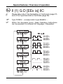
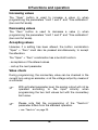
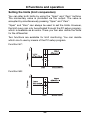
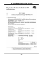
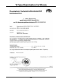
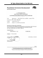
1
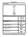
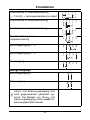
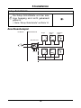
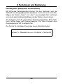
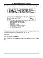
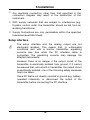
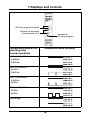
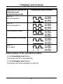
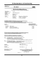
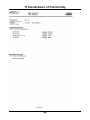
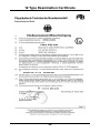
J dTRANS T02 Ex Programmierbarer Messumformer Programmable transmitter B 70.7025.0 Betriebsanleitung Operating Instructions 03.07/00396221 Besonderheiten / Bedienübersicht II (1) G D [EEx ia] IIC A Die Konformitätserklärung (Seite 27) und die Baumusterprüfbescheinigung (Seite 29) sind zu beachten. H Der Typ 707025/... entspricht dem Typ 956525/.... H Innerhalb der EU-Mitgliedsstaaten kann diese Betriebsanleitung auf Wunsch in einer anderen EU-Landessprache angefordert werden. 1 Zielgruppe / Normenkonformität Zielgruppe Der Messumformer JUMO dTRANS T02 Ex Typ 707025/... dient zur Signalumwandlung von Widerstandsthermometern, Thermoelementen, Widerstands-, Spannungs- und Stromgebern in die Einheitssignale 0 … 20mA, 4 … 20mA bzw. 0 … 10V. Eingang, Ausgang und weitere Konfigurationsparameter sind über eine Schnittstelle mittels PC-Programm frei einstellbar. Der Messumformer ist zur Montage auf Tragschiene außerhalb des explosionsgefährdeten Bereichs vorgesehen. Normenkonformität Die grundlegenden Sicherheits- und Gesundheitsanforderungen werden erfüllt durch Übereinstimmung mit: - EN 61 326: 2001 - EN 61 010-1: 2001 - EN 50 014 + A1 + A2: 1997 - EN 50 020: 1994 3 2 Sicherheitshinweise - Die Errichtung und der Betrieb des Messumformers muss unter Berücksichtigung dieser Betriebsanleitung und den für sie gültigen Regeln und Normen erfolgen. - Der Messumformer ist zur Montage auf Tragschiene außerhalb des explosionsgefährdeten Bereiches vorgesehen. Versorgung und Ausgang des Messumformers müssen in der nicht eigensicheren Zone liegen. - Der Sensorstromkreis kann entsprechend der Gerätegruppe „II“ Kategorie „(1) G D“ in die Zone 0, Zone 1 und Zone 2 geführt werden. - Feldgeräte, die an den Sensorstromkreis zum Einsatz in staubexplosionsgefährdeten Bereich angeschlossen werden, bedürfen einer gesonderten Baumusterprüfung. - Eingang, Ausgang und weitere Konfigurationsparameter sind über eine Schnittstelle mittels PC-Programm frei einstellbar. - Die höchstzulässige Umgebungstemperatur für den Messumformer beträgt +60°C. - Der Messumformer ist so zu errichten, dass auch für die Anschlussteile ein Schutzgrad von mindestens IP 20 gemäß EN 60 529 erreicht wird. - Bei der Errichtung und dem Betrieb des Messumformers ist darauf zu achten, dass keine elektrostatische Aufladung auftreten kann. - Der eigensichere Sensorstromkreis ist von allen nichteigensicheren Stromkreisen bis zu einem Scheitelwert der Nennspannung von 375V sicher galvanisch getrennt. 4 2 Sicherheitshinweise Auszug aus der EG-Baumusterprüfbescheinigung PTB 01 ATEX 2149 Messumformer 707025 Versorgungsstromkreis (Höchstwerte an den Klemmen L1(L+) und N(L-) und PE) II (1) G D [EEx ia] IIC AC 230V ±10%, 48…63Hz oder AC/DC 20 … 53V, 48…63Hz Sicherheitstechnische Maximalspannung Um = 253V Ausgangsstromkreis (Klemmen 9(+) und 10(-) ) 0 … 20mA (Um = 253V) Ausgangsstromkreis (Klemmen 11(-) und 12(+) ) 0 … 10V (Um = 253V) Setup-Stromkreis 5V - TTL-Pegel (Um = 253V) Sensorstromkreis (Klemmen 1 … 5) in Zündschutzart Eigensicherheit EEx ia IIB/IIC bzw. EEx ib IIB/IIC Uo = 6,0V / Io = 18,9mA Po = 28,4mW Kennlinie: linear Li ≈ 0 / Ci ≈ 0 höchstzulässige äußere Induktivität/Kapazität EEx ia IIB / EEx ib IIB EEx ia IIC / EEx ib IIC Lo = 400mH / Co = 1000µF Lo = 100mH / Co = 40µF Bei Vorhandensein konzentrierter Kapazitäten und / oder Induktivitäten im eigensicheren Sensorstromkreis gelten: höchstzulässige äußere Induktivität/Kapazität EEx ia IIB / EEx ib IIB EEx ia IIC / EEx ib IIC Lo = 20mH / Co = 8µF Lo = 10mH / Co = 1,7µF 5 3 Typenerklärung / -schilder JUMO dTRANS T02 Ex (1) Grundausführung 707025 x x 888 999 x x 888 999 x x dTRANS T02 Ex programmierbarer Messumformer mit Ex-Schutz II (1) G D [EEx ia] IIC (2) Eingang (programmierbar) Werkseitig eingestellt (Pt100 DIN vl / 0 … 100°C) Konfiguration nach Kundenangaben1 (3) Ausgang (eingeprägter Gleichstrom - programmierbar) Werkseitig eingestellt (4 … 20mA) Konfiguration nach Kundenangaben (4 … 20mA oder 0 … 10V bzw. 2 … 10V) (4) Spannungsversorgung 03 AC 230V ±10%, 48 … 63Hz 22 AC/DC 20 …53V, 48 … 63Hz Bestellschlüssel Bestellbeispiel (1) (2) (3) (4) 707025 / 707025 / 888 - 888 - 03 1. Bei der Konfiguration nach Kundenangaben sind die Fühlerart und der Messbereich im Klartext anzugeben Serienmäßiges Zubehör - 1 Betriebsanleitung 70.7025.0 Zubehör - PC-Setup-Programm, mehrsprachig - PC-Interface mit TTL/RS232-Umsetzer und Adapter (Buchse) - PC-Interface mit USB/TTL-Umsetzer, Adapter (Buchse) und Adapter (Stifte) 6 3 Typenerklärung / -schilder Die nachfolgende abgebildeten Typenschilder befinden sich auf dem Gehäuse des Messumformers. Der F-Nr. (Fabrikations-Nummer) kann das Produktionsdatum (Jahr/ Woche) entnommen werden. Es handelt sich hierbei um die Zeichen 12, 13, 14, 15. Beispiel: F-Nr. 0041367101001360014 Der Messumformer wurde demnach in der 36. Woche 2001 produziert. 7 4 Technische Daten - Kennzeichnung: II (1) G D [EEx ia] IIC - EG-Baumusterprüfbescheinigung: PTB 01 ATEX 2149 siehe Kapitel 2 „Sicherheitshinweise“ und siehe Kapitel 12 „Baumusterprüfbescheinigung“ - Konformitätserklärung: siehe Kapitel 11 „Konformitätserklärung“ - Typenblatt: T 70.7020 8 5 Installation Für das Errichten/Betreiben sind die Vorschriften gemäß ElexV und diese Betriebsanleitung maßgebend. Die höchstzulässige Umgebungstemperatur für den Messumformer von +60°C ist unbedingt einzuhalten. Abmessungen 1 2 3 4 5 6 7 8 dTRANS T02 Ex Power Status Span Zero 9 10 11 12 L1 N 15 PE (L+) (L-) Weitere Installationshinweise entnehmen Sie bitte Kapitel 2 „Sicherheitshinweise“. 9 5 Installation Anschlussplan 1 2 3 4 5 6 7 8 dTRANS T02 Ex Power Status Span Zero 9 10 11 12 L1 N 15 PE (L+) (L-) Anschluss für Spannungsversorgung lt. Typenschild Analoge Eingänge (Ex) Thermoelement Widerstandsthermometer in Zweileiterschaltung 1 2 3 4 RL RA=RL RA RL ≤ 15Ω (RL = Leitungswiderstand je Leiter) Widerstandsthermometer in Dreileiterschaltung 1 5 2 3 4 5 3 4 5 Widerstandsthermometer in Vierleiterschaltung 1 2 10 5 Installation Potentiometer in Zweileiterschaltung 1 RL ≤ 15Ω (RL = Leitungswiderstand je Leiter) 2 3 4 5 RL RA=RL RA Potentiometer in Dreileiterschaltung 1 2 3 4 5 Potentiometer in Vierleiterschaltung 1 2 3 4 5 Widerstandsferngeber in Dreileiterschaltung Spannungseingang < 1V Spannungseingang ≥ 1V Stromeingang Analoge Ausgänge Spannungsausgang Stromausgang A Strom- und Spannungsausgang sind nicht gegeneinander galvanisch getrennt. Die Massen von Strom- und Spannungsausgang dürfen nicht zusammengeschaltet werden. 11 5 Installation Setup-Schnittstelle A Die Setup-Schnittstelle und der analoge Ausgang sind nicht galvanisch getrennt. v Siehe “Setup-Schnittstelle” auf Seite 14. Anschlussbeispiel Ex-Bereich Nicht Ex-Bereich Regler Messumformer + Anzeigegerät - + Registriergerät - + - + - + = ~ 4...20 mA / 0...20 mA - L1 N PE + - + + 0...10 V - 12 - 5 Installation Installationshinweise ! Sowohl bei der Wahl des Leitungsmaterials bei der Installation als auch beim elektrischen Anschluss des Gerätes sind die Vorschriften der VDE 0100 „Bestimmungen über das Errichten von Starkstromanlagen mit Nennspannungen unter 1000V“ bzw. die jeweiligen Landesvorschriften zu beachten. ! Der elektrische Anschluss, sowie Arbeiten im Geräteinneren dürfen ausschließlich von Fachpersonal durchgeführt werden. ! Das Gerät allpolig vom Netz trennen, wenn bei Arbeiten spannungsführende Teile berührt werden können. ! Ein Strombegrenzungswiderstand (Sicherheitsfunktion) unterbricht bei einem Kurzschluss im Messumformer den Netzstromkreis. Die äußere Absicherung der Spannungsversorgung sollte einen Wert von 1A (träge) nicht überschreiten. ! In der Nähe des Gerätes keine magnetischen oder elektrischen Felder, z.B. durch Transformatoren, Funksprechgeräte oder elektrostatische Entladungen entstehen lassen. ! Induktive Verbraucher (Relais, Magnetventile etc.) nicht in Gerätenähe installieren und durch RC- oder Funkenlöschkombinationen bzw. Freilaufdioden entstören. ! Eingangs-, Ausgangs- und Versorgungsleitungen räumlich voneinander getrennt und nicht parallel zueinander verlegen. Hinund Rückleitungen nebeneinander führen und nach Möglichkeit verdrillen. ! Alle Ein- und Ausgangsleitungen ohne Verbindung zum Spannungsversorgungsnetz müssen mit geschirmten und verdrillten Leitungen verlegt werden. Die Schirmung muss geräteseitig auf Erdpotential gelegt werden. ! An die Netzklemmen des Gerätes keine weiteren Verbraucher anschließen. 13 5 Installation ! Der Messumformer ist zur Montage auf Tragschienen außerhalb des explosionsgefährdeten Bereiches vorgesehen. ! Ein vom Anschlussplan abweichender elektrischer Anschluss kann zur Zerstörung des Gerätes führen. ! Bei störungsbelasteten Netzen (z. B. Thyristorsteuerungen) sollte das Gerät über einen Trenntransformator gespeist werden. ! Netzschwankungen sind nur im Rahmen der angegebenen Toleranzen zulässig (siehe Typenblatt). Setup-Schnittstelle A Die Setup-Schnittstelle und der analoge Ausgang sind nicht galvanisch getrennt. Unter ungünstigen Umständen können daher, bei einem eingebauten Messumformer, Ausgleichsströme fließen, wenn das PC-Interface angeschlossen wird. Die Ausgleichsströme können Schäden bei den beteiligten Geräten bewirken. Keine Gefahr besteht, wenn der Ausgangsstromkreis des Messumformers galvanisch von Erde getrennt ist. Wenn nicht sichergestellt ist, dass bei einem eingebauten Messumformer der Ausgangskreis galvanisch getrennt ist, sollte eine der folgenden Sicherheitsmaßnahmen verwendet werden: Einen Rechner ohne galvanische Kopplung mit Erde verwenden (z.B. einen Notebook im Batteriebetrieb) oder den Ausgang des Messumformers abklemmen bevor das PC-Interface angeschlossen wird. 14 6 Instandhaltung Die für die Wartung/Instandsetzung/Prüfung geltenden Bestimmungen sind einzuhalten. Im Rahmen der Wartung sind vor allem Teile zu prüfen, von denen die Zündschutzart abhängt. Eine Konfiguration des Messumformers über den Setup-Kreis darf niemals im explosionsgefährdeten Bereich erfolgen. Außerhalb des explosionsgefährdeten Bereiches darf der Anschluss aus sicherheitstechnischen Gründen (Schutz der ex-relevanten Bauelemente) nur zur kurzzeitigen Konfiguration erfolgen. 15 7 Anzeige- und Bedienelemente 1 2 3 4 5 6 7 8 dTRANS T02 Ex Power Status LEDs für Betriebszustand Span Tasten zur Bedienung der Parameterebene Zero Schnittstelle für PC-Setup-Programm 9 10 11 12 L1 N 15 PE (L+) (L-) Betriebszustand in der Bedienerebene (Normalbetrieb) Leucht-/Blinkverhalten Limitkomparator 1 inaktiv 2 inaktiv Limitkomparator 1 aktiv 2 inaktiv Limitkomparator 1 inaktiv 2 aktiv Limitkomparator 1 aktiv 2 aktiv Overrange 16 7 Anzeige- und Bedienelemente Betriebszustand in der Parameterebene (Programmier-Modus) Leucht-/Blinkverhalten Grenzwert von Limitkomparator 1 Grenzwert von Limitkomparator 2 Feinabgleich (Nullpunkt) Feinabgleich (Endwert) Teach In (0-%-Wert) Unterscheidung der Betriebszustände - Im Betriebszustand Bedienerebene ist die Power-LED permanent an. - Im Betriebszustand Parameterebene blinkt die Power-LED (zu gleichen Teilen an und aus). 17 8 Funktionen und Bedienung Mit Hilfe der Tasten „Span“ und „Zero“ in Verbindung mit den in Kapitel 7 „Anzeige- und Bedienelemente“ bereits beschriebenen Blinkzyklen der beiden LEDs „Power“ und „Status“ können Sie den Messumformer bedienen. Bei der Bedienung unterscheiden sich zwei Betriebszustände: - Bedienerebene (Normalbetrieb) - Parameterebene (Programmier-Modus) Bedienerebene In der Bedienerebene befindet sich der Messumformer 2 Sekunden nach dem Anlegen der Versorgungsspannung, oder wenn die Parameterebene verlassen wurde. Parameterebene In die Parameterebene gelangen Sie, durch gleichzeitiges Betätigen der beiden Tasten „Span“ und „Zero“ (mindestens 5 Sekunden lang). In der Ebene können folgende Funktionen programmiert werden: - Grenzwert des 1. Limitkomparators - Grenzwert des 2. Limitkomparators - Feinabgleich (Nullpunkt) - Feinabgleich (Endwert) - Teach In Die Parameterebene wird verlassen (beendet), nachdem Sie den Parameter „Teach In“ editiert oder mindestens 20 Sekunden lang keine Taste betätigt haben. Die einzelnen Parameter können nacheinander verändert werden. Von Parameter zu Parameter gelangen Sie durch gleichzeitiges Betätigen der beide Tasten „Span“ und „Zero“ für die Dauer von kleiner 1 Sekunde. 18 8 Funktionen und Bedienung Werte erhöhen Beim Programmieren der Parameter „Grenzwert 1 und 2“ sowie „Feinabgleich“ (Nullpunkt und Endwert) dient die Taste „Span“ zum Erhöhen eines Wertes (+). Werte verringern Beim Programmieren der Parameter „Grenzwert 1 und 2“ sowie „Feinabgleich“ (Nullpunkt und Endwert) dient die Taste „Zero“ zum Verringern eines Wertes (-). Werte übernehmen Wurde eine Einstellung geändert, müssen Sie ebenfalls die Tastenkombination „Span“ + „Zero“ gleichzeitig betätigen, um die Änderung zu übernehmen. „Span“ + „Zero“ hat eine doppelte Bedeutung: - Übernahme von geänderten Werten - Aufruf des nächsten Parameters Wertkontrolle Der aktuelle Wert kann während der Programmierung mit Hilfe eines Strommessers in der Stromschleife bzw. mit Hilfe eines Spannungsmessers am Spannungsausgang kontrolliert werden. H H Ist die Parameterebene aktiv, wird bei der Programmierung der beiden Grenzwerte der Analogausgang nicht entsprechend der Eingangsbeschaltung angesteuert, sondern mit dem aktuellen Grenzwert. Bitte beachten Sie, dass die Programmierung des Parameters „Teach In“ von der Standardbedienung abweicht. v Siehe “Teach In” auf Seite 23. 19 8 Funktionen und Bedienung Grenzwerte (Limitkomparatoren) einstellen Sie können die beiden Grenzwerte mit Hilfe der Tasten „Span“ und „Zero“ verändern. Der aktuelle Wert wird über den Ausgang ausgegeben. Übernommen wird der Wert durch gleichzeitiges Betätigen der Tasten „Span“ und „Zero“. Die Einstellung der Grenzwerte über die Tasten „Span“ und „Zero“ ist immer möglich. Aktiviert werden kann die Grenzwertabfrage jedoch nur mit Hilfe des als Typenzusatz verfügbaren PC-Setup-Programmes. Dort bestimmen Sie auch die Hysterese-Grenzen. Bei der Grenzwertüberwachung stehen zwei Arten zur Verfügung. Welche eingesetzt wird, können Sie mit Hilfe des PC-Setup-Programmes entscheiden. Funktionsweise lk7: Funktionsweise lk8: 20 8 Funktionen und Bedienung H Die Grenzwerte (Limitkomparatoren) werden nur über die Status- und die Power-LED angezeigt. Die Open-Collector-Ausgänge sind - im Gegensatz zu den Messumformern 707021/... (PCP) und 707022/... (LCD) beim Typ 707025/... (Ex) nicht vorhanden. Fehlerausgang Die Funktion „Fehlerausgang“ kann nur mit dem Setup-Programm aktiviert werden. Ist die Funktion „Fehlerausgang“ aktiv, werden folgende Fehler überwacht: - Fühlerbruch - Fühlerkurzschluss (nur Widerstandsthermometer) - Messbereichsüberschreitung - Messbereichsunterschreitung - interne Fehler (Pt100 der Vergleichsstelle defekt, ...) Tritt eines der Ereignisse ein, wird das Blinkverhalten für Overrange aktiviert. v Siehe “Leucht-/Blinkverhalten” auf Seite 16. 21 8 Funktionen und Bedienung Feinabgleich (Nullpunkt und Endwert) Mit Hilfe des Feinabgleiches können Sie den Nullpunkt und die Steilheit des Ausgangssignales anpassen. Auch hier wird durch Betätigen der Tasten „Span“ und „Zero“ der jeweilige Wert verändert und durch gleichzeitiges Betätigen beider Tasten übernommen. Am Ausgang wird der gemessene Istwert ausgegeben. Beim Nullpunkt sollte dieser dem Ausgangssignal 0%, beim Endwert dem Ausgangssignal 100% entsprechen. Die Formel für die Berechnung des neuen Istwertes lautet: Istwert = Messwert skaliert × Endwert + Nullpunkt 22 8 Funktionen und Bedienung Teach In Der Parameter „Teach In“ dient dazu, den 0-%-Wert festzulegen. Am Ausgang wird während der Programmierung der Nullwert ausgegeben (z.B. 4mA). Durch Betätigen der Taste „Zero“ (nur Zero, nicht zusammen mit Span) wird der Wert übernommen. Nach einem Timeout ohne Übernahme steht der alte Wert wieder zur Verfügung. Beispiel: Die Stellung eines Ventils wird von einem Potentiometer erfasst. Das Potentiometer hat einen Bereich von 50 bis 150Ω, wobei 50Ω dem geschlossenen Ventil entsprechen. Der Messbereich ist wie folgt programmiert: - Potentiometer 50 … 150 Ω - Ausgang 0 … 20mA Durch mechanische Toleranzen ist die Potistellung jedoch bei geschlossenem Ventil 52Ω, woraus sich ein Ausgangsstrom von 0,4mA ergibt. Der Fehler kann durch die Funktion „Teach In“ wie folgt beseitigt werden: - Ventil schließen. - Parameterebene aufrufen und „Teach In“ auswählen (am Ausgang sollten dann 0,4mA anliegen). - Taste „Zero“ betätigen, worauf sich der Ausgang auf 0mA ändern muss. - Änderung durch gleichzeitiges Betätigen der Tasten „Span“ und „Zero“ bestätigen. - Die Parameterebene verlassen (entweder nach Timeout von 20s oder durch erneutes Betätigen von „Span und Zero“). 23 9 Hinweise ... ... zur Bedienung innerhalb der Parameterebene H Das gleichzeitige Betätigen der Tasten „Span“ und „Zero“ als Bestätigung einer Werteingabe setzt voraus, dass vorher mindestens einmal eine der beiden Tasten alleine betätigt wurde. Ist dies nicht der Fall, wird die Betätigung als Aufruf des nächsten Parameters angesehen. H Sollen beide Tasten gleichzeitig betätigt werden, aber aus Versehen wird eine der beiden zu früh gedrückt, erfolgt dadurch automatisch eine Wertveränderung. Das nächste wirklich gleichzeitige Betätigen von „Span“ und „Zero“ bewirkt zunächst die Übernahme des geänderten Wertes. Erst ein erneutes Betätigen beider Tasten bewirkt, dass der nächste Parameter (oder der Normalbetrieb) aufgerufen wird. H H Soll der Wert bei einer versehentlichen Änderung nicht übernommen werden, ist der Timeout von 20s abzuwarten. Das Gerät springt dann automatisch in den Normalbetrieb, ohne die Änderung zu übernehmen. Bitte beachten Sie, dass die Programmierung des Parameters „Teach In“ von der Standardbedienung abweicht. v Siehe “Teach In” auf Seite 23. H Die Einstellung der Grenzwerte über die Tasten „Span“ und „Zero“ ist immer möglich. Aktiviert werden kann die Grenzwertabfrage jedoch nur mit Hilfe des als Typenzusatz verfügbaren PC-Setup-Programmes. Dort bestimmen Sie auch die Hysterese-Grenzen. 24 9 Hinweise ... ... allgemeiner Art H Kann kein Parameter verändert werden, haben Sie vielleicht mit Hilfe des Setup-Programmes die Bedienung am Gerät verriegelt. Prüfen Sie die Einstellung durch das Setup-Programm. Nur, wenn für die entsprechende Ebene keine Verriegelung besteht, können die Einstellungen am Gerät geändert werden. H Beide Ausgänge (Strom und Spannung) stehen immer gleichzeitig zur Verfügung. Allerdings besitzt der Ausgang, der nicht im Setup-Programm oder durch die Default-Einstellung aktiviert wurde, nur eine Genauigkeit von ca. ± 2% vom Endwert. 25 10 PC-Setup-Programm Mit der Bedienung am Messumformer lassen sich nur einige wenige Parameter ändern. Mit dem als Typenzusatz erhältlichen PC-SetupProgramm lassen sich alle Parameter des Messumformers bequem ändern. Über die Setup-Schnittstelle werden der Messumformer und der PC über das „PC-Interface“ miteinander verbunden. Konfigurierbare Parameter: - TAG-Number (10 Zeichen) - Analoger Eingang (Sensortyp) - Anschlussart (2-/3-/4-Leiterschaltung) - externe oder konstante Vergleichsstelle - kundenspezifische Linearisierung - Messbereichsgrenzen (Anfang und Ende) - Ausgangssignal Strom/Spannung/Frequenz steigend/fallend - digitales Filter - Verhalten bei Fühlerbruch/-kurzschluss - Nachkalibrierung/Feinabgleich - Gerätekalibrierung - Grenzwert/Hysterese der Limitkomparatoren - Datei-Info-Text Weitere Vorteile des PC-Setup-Programms - mehrere verschiedene Einstellungen verwalten - eine Einstellung für mehrere Messumformer - Einstellung zur Dokumentation ausdrucken - Bedienung umschaltbar in den GMA-Standard 26 11 Konformitätserklärung 27 11 Konformitätserklärung 28 12 Baumusterprüfbescheinigung 29 12 Baumusterprüfbescheinigung 30 12 Baumusterprüfbescheinigung 31 12 Baumusterprüfbescheinigung 32 12 Baumusterprüfbescheinigung 33 JUMO GmbH & Co. KG Hausadresse: Moltkestraße 13 - 31 36039 Fulda, Germany Lieferadresse: Mackenrodtstraße 14 36039 Fulda, Germany Postadresse: 36035 Fulda, Germany Telefon: +49 661 6003-727 Telefax: +49 661 6003-508 E-Mail: [email protected] Internet: www.jumo.net JUMO Mess- und Regelgeräte Ges.m.b.H. Pfarrgasse 48 1232 Wien, Austria Telefon: +43 1 610610 Telefax: +43 1 6106140 E-Mail: [email protected] Internet: www.jumo.at JUMO Mess- und Regeltechnik AG Laubisrütistrasse 70 8712 Stäfa, Switzerland Telefon: +41 44 928 24 44 Telefax: +41 44 928 24 48 E-Mail: [email protected] Internet: www.jumo.ch J dTRANS T02 Ex Programmable transmitter B 70.7025.0 Operating Instructions Special features / Overview of operation A H H II (1) G D [EEx ia] IIC Please take note of the Declaration of Conformity (page 27) and of the Type Examination Certificate (page 29). Type 707025/... corresponds to type 956525/.... Within the European Union, these Operating Instructions can be supplied in a different EU language, if requested. 1 Intended use / Conformity with standards Intended use The JUMO dTRANS T02 Ex type 707025/... transmitter is used for converting the signals from resistance thermometers, thermocouples, resistance, voltage and current sources into standard 0 — 20mA, 4 — 20mA or 0 — 10V signals. Input, output and additional configuration parameters can be freely set through the PC program, via an interface. The transmitter is intended for rail mounting outside the hazardous area. Conformity with standards The fundamental safety and health requirements are fulfilled through compliance with the following standards: - EN 61 326: 2001 - EN 61 010-1: 2001 - EN 50 014 + A1 + A2: 1997 - EN 50 020: 1994 3 2 Safety notes - The transmitter must be set up and operated in accordance with these operating instructions and the regulations and standards relating to it. - The transmitter is intended for rail mounting outside the hazardous area. Supply and output of the transmitter must be located in the nonintrinsically safe zone. - In accordance with equipment group “II” category “(1) G D”, the sensor circuit may be located in Zone 0, Zone 1 and Zone 2. - Field devices connected to the sensor circuit for use in areas with a dust explosion hazard require a separate type examination. - Input, output and other configuration parameters can be freely set through the PC program, via an interface. - The maximum permissible transmitter is +60°C. ambient temperature for the - The transmitter must be set up in such a way as to provide at least IP20 protection as per EN 60 529, also for the connecting parts. - During setting up and operation of the transmitter, any build-up of electrostatic charge must be avoided. - The intrinsically safe sensor circuit is safely isolated from the nonintrinsically safe circuits, up to a peak value of 375V of the nominal voltage. 4 2 Safety notes Extract from the EC Type Examination Certificate PTB 01 ATEX 2149 Transmitter 707025 Supply circuit (maximum values at the terminals L1(L+) and N(L-) and PE) Output circuit (terminals 9(+) and 10(-) ) II (1) G D [EEx ia] IIC 230V AC ±10%, 48 — 63Hz or 20 — 53V AC/DC, 48 — 63Hz max. safe voltage Um = 253V 0 — 20mA (Um = 253V) Output circuit (terminals 11(-) and 12(+) ) 0 — 10V (Um = 253V) Setup circuit 5V TTL level (Um = 253V) Sensor circuit (terminals 1 — 5) intrinsically safe protection EEx ia IIB/IIC or EEx ib IIB/IIC Uo = 6.0V / Io = 18.9mA Po = 28.4mW characteristic: linear Li ≈ 0 / Ci ≈ 0 Max. permissible external inductance /capacitance EEx ia IIB / EEx ib IIB EEx ia IIC / EEx ib IIC Lo = 400mH / Co = 1000µF Lo = 100mH / Co = 40µF In the presence of lumped capacitance and / or inductance in the intrinsically safe sensor circuit the following applies: max. permissible external inductance/capacitance EEx ia IIB / EEx ib IIB EEx ia IIC / EEx ib IIC Lo = 20mH / Co = 8µF Lo = 10mH / Co = 1.7µF 5 3 Type designation / labels JUMO dTRANS T02 Ex (1) Basic version dTRANS T02 Ex programmable transmitter with Ex protection II (1) G D [EEx ia] IIC 707025 x x 888 999 x x 888 999 x x (2) Input (programmable) factory-set (Pt100 DIN 4-wire / 0 — 100°C) configuration to customer specification1 (3) Output (proportional DC current - programmable) factory-set (4 — 20mA) configuration to customer specification (4 — 20mA or 0 — 10V or 2 — 10V) (4) Supply 03 230V AC ±10%, 48 — 63Hz 22 20 — 53V AC/DC, 48 — 63Hz Order code Order example (1) (2) (3) (4) 707025 / 707025 / 888 - 888 - 03 1. For configuration to customer specification, probe type and range have to be specified in plain text. Standard accessories - 1 Operating Instructions 70.7025.0 Accessories - PC setup program, multilingual - PC interface with TTL/RS232 converter and adapter (sockets) - PC interface with USB/TTL converter, adapter (sockets) and adapter (pins) 6 3 Type designation / labels The labels shown below are attached to the transmitter housing. * ** *** **** or specification of range and sensor details on sales no. and serial number as per order factory-set (0 — 20 mA) configuration to customer specification (4 — 20 mA or 0 — 10V or 2 — 10V) or a different supply voltage The serial No. (F-Nr.) indicates the production date (year/week). The figures concerned are in positions 12, 13, 14, 15. Example: F-Nr. 0041367101001360014 This shows that the transmitter was manufactured in 2001, week 36. 7 4 Technical data - Marking: II (1) G D [EEx ia] IIC - EC Type Examination Certificate: PTB 01 ATEX 2149 see Chapter 2 “Safety notes” and Chapter 12 “Type Examination Certificate” - Declaration of Conformity: see Chapter 11 “Declaration of Conformity” - Data Sheet T 70.7020 8 5 Installation The regulations according to ElexV and these operating instructions apply when setting up and operating the transmitter. It is essential to observe the maximum permissible ambient temperature +60°C. Dimensions 1 2 3 4 5 6 7 8 dTRANS T02 Ex Power Status Span Zero 9 10 11 12 L1 N 15 PE (L+) (L-) Additional installation notes can be found in Chapter 2 “Safety notes”. 9 5 Installation Connection diagram 1 2 3 4 5 6 7 8 dTRANS T02 Ex Power Status Span Zero 9 10 11 12 L1 N 15 PE (L+) (L-) Connection for Supply as on nameplate Analog inputs (Ex) Thermocouple Resistance thermometer in 2-wire circuit RL ≤ 15Ω (RL = lead resistance per conductor) 1 Resistance thermometer in 3-wire circuit 1 2 3 4 5 RL RA=RL RA 2 3 4 5 3 4 5 Resistance thermometer in 4-wire circuitb 1 2 10 5 Installation Potentiometer in 2-wire circuit 1 2 3 4 5 RL RA=RL RL ≤ 15Ω (RL = lead resistance per conductor) Potentiometer in 3-wire circuit 1 2 3 4 5 Potentiometer in 4-wire circuit 1 2 3 4 5 Resistance transmitter in 3-wire circuit Voltage input < 1V Voltage input ≥ 1V Current input Analog outputs Voltage output Current output A Current and voltage outputs are not electrically isolated. The negative poles of the voltage and current outputs must not be joined together. 11 RA 5 Installation Setup interface A The setup interface and the analog output are not electrically isolated. v see “Setup interface” on page 14. Connection example 12 5 Installation Installation notes ! The choice of cable, the installation and the electrical connection must conform to the requirements of VDE 0100 “Regulations on the Installation of Power Circuits with Nominal Voltages below 1000 V” or the appropriate local regulations. ! The electrical connection, as well as work inside the unit, must only be carried out by qualified personnel. ! If contact with live parts is possible while working on the unit, it must be completely disconnected from the supply. ! A current limiting resistor (safety function) protects the supply circuit in the event of a short-circuit in the transmitter. The external fusing of the supply should not be rated above 1A (slow). ! Stray electromagnetic fields, e.g. from transformers, mobile phones or electrostatic discharge must be avoided in the vicinity of the transmitter. ! Do not install inductive loads (relays, solenoid valves etc.) close to the transmitter. Fit RC or spark quenching combinations, or free-wheeling diodes, for interference suppression. ! Run input, output and supply cables separately and not parallel to one another. Run out/return cables next to each other and twist them, if possible. ! Route input and output cables without any connection to the mains supply as twisted and screened cables. Earth the screen on the instrument side. ! Do not connect any additional loads to the supply terminals of the instrument. ! The transmitter is intended for rail mounting outside the hazardous area. 13 5 Installation ! Any electrical connection other than that specified in the connection diagram may result in the destruction of the instrument. ! With supply networks that are subject to interference (e.g. thyristor control units), the transmitter should be fed from an isolating transformer. ! Supply fluctuations are only permissible within the specified tolerances (see Data Sheet). Setup interface A The setup interface and the analog output are not electrically isolated. This means that, in unfavorable conditions and with a built-in transmitter, equalizing currents may flow when the PC interface cable is connected. The equalizing currents may damage the affected instruments. However, there is no danger if the output circuit of the transmitter is electrically isolated from ground. If it cannot be ensured that, with a built-in transmitter, the output circuit is electrically isolated, one of the following safety measures has to be taken: Use a PC that is not directly coupled to ground (e.g. batteryoperated notebook), or disconnect the output of the transmitter before connecting the PC interface. 14 6 Maintenance The appropriate regulations concerning maintenance, repair and testing must be observed. In particular, all parts on which explosion protection depends must be checked during maintenance. The transmitter must never be configured inside the hazardous area via the setup circuit. For safety reasons (protection of Ex-relevant components), the connection outside the hazardous area may only be made for the purpose of brief configuration. 15 7 Displays and controls 1 2 3 4 5 6 7 8 dTRANS T02 Ex Power Status LEDs for operational status Span Buttons for operating the parameter level Zero Interface for PC setup program 9 10 11 12 L1 N 15 PE (L+) (L-) Operational status at the operating level (normal operation) Illumination/blink behavior Limit comparator 1 inactive 2 inactive Limit comparator 1 active 2 inactive Limit comparator 1 inactive 2 active Limit comparator 1 active 2 active Overrange 16 7 Displays and controls Operational status at the parameter level (programming mode) Illumination/blink behavior Limit for limit comparator 1 Limit for limit comparator 2 Fine calibration (zero) Fine calibration (full scale) Teach-in (0 % value) Differentiation of the operational states - In the Operating level status, the power LED is on permanently. - In the Parameter level status, the power LED blinks (equally on and off). 17 8 Functions and operation You can operate the transmitter by using the “Span” and “Zero” buttons, in conjunction with the blink cycles of the “Power” and “Status” LEDs already described in Chapter 7 “Displays and controls”. In use, two operational states can be distinguished: - Operating level (normal operation) - Parameter level (programming mode) Operating level The transmitter is at the operating level two seconds after power ON, or after leaving the parameter level. Parameter level You can access the parameter level by simultaneously pressing the buttons for “Span” and “Zero” (for at least 5 seconds). The following functions can be programmed at this level: - Limit for limit comparator 1 - Limit for limit comparator 2 - Fine calibration (zero) - Fine calibration (full scale) - Teach-in You can exit the parameter level (quit) after editing the “Teach-in” parameter, or if no button has been pressed for at least 20 seconds. The individual parameters can be altered, one after another. You can move from parameter to parameter by simultaneously pressing the buttons “Span” and “Zero” for less than 1 second. 18 8 Functions and operation Increasing values The “Span” button is used to increase a value (+) when programming the parameters “Limit 1 and 2” and “Fine calibration” (zero and full scale). Decreasing values The “Zero” button is used to decrease a value (-) when programming the parameters “Limit 1 and 2” and “Fine calibration” (zero and full scale). Accepting values Likewise, if a setting has been altered, the button combination “Span” + “Zero” must also be pressed simultaneously, to accept the alteration. The “Span” + “Zero” combination has a twofold function: - acceptance of the altered values - call up the next parameter Value check During programming, the momentary value can be checked in the current loop using an ammeter, or at the voltage output by means of a voltmeter. H H With activated parameter level, the analog output will not be operated according to the input circuitry when programming the two limit values but with the momentary limit value. Please note that the programming of the “Teach-in” parameter differs from the standard operation. v see “Teach-in” on page 23. 19 8 Functions and operation Setting the limits (limit comparators) You can alter both limits by using the “Span” and “Zero” buttons. The momentary value is produced via the output. The value is accepted by simultaneously pressing “Span” and “Zero”. “Span” and “Zero” can always be used to set the limits. However, the limit query can only be activated through the PC setup program, which is available as an extra. There you can also define the limits for the differential. Two functions are available for limit monitoring. You can decide which one to use by means of the PC setup program. Function lk7: Function lk8: 20 8 Functions and operation H The limits (limit comparators) are indicated only via the status and power LEDs. Unlike the transmitters 707021/... (PCP) and 707022/... (LCD), the open-collector outputs are not available on type 707025/... (Ex). Fault output The "fault output" function can only be activated through the setup program. If the "fault output" function is active, the following faults will be monitored: - probe break - probe short-circuit (RTD only) - overrange - underrange - internal faults (Pt100 of cold junction is faulty, ...) If any of these events occur, the blink response for overrange will be activated. v see “Illumination/blink behavior” on page 16. 21 8 Functions and operation Fine calibration (zero and full scale) Fine calibration can be used to adjust the zero and slope of the output signal. Here, too, the “Span” and “Zero” buttons serve to alter the appropriate values, or to accept them by simultaneously pressing both buttons. The measured value is produced at the output. At zero point, this should correspond to the output signal 0%, at full scale to the output signal 100%. The formula for calculating the new value is: output value = measured valuescaled x full scale + zero point 22 8 Functions and operation Teach-in The “Teach-in” parameter serves to define the 0 % value. During programming the zero point is produced at the output (e.g. 4mA). This value is accepted by pressing the “Zero” button (“Zero” only, not together with “Span”). After a time-out without acceptance, the old value will be available again. Example: The position of a valve is detected by a potentiometer. The potentiometer covers the range 50 to 150Ω, with 50Ω corresponding to the valve closed. The range is programmed as follows: - potentiometer 50 — 150 Ω - output 0 — 20mA However, because of mechanical tolerances, the potentiometer position is 52Ω with the valve closed, thus resulting in an output current of 0.4mA. Thanks to the “teach-in” function, this error can be eliminated as follows: - close valve - call parameter level and select “Teach-in” (0.4mA should then be present at the output). - press the “Zero” button – the output must now change to 0mA. - confirm alteration by simultaneously pressing the “Span” and “Zero” buttons. - exit the parameter level (either after a time-out of 20sec, or by pressing “Span” and “Zero” again). 23 9 Tips ... ... on operation within the parameter level H A value can only be confirmed by simultaneously pressing the “Span” and ”Zero” buttons when at least one of the buttons has previously been pressed by itself. If this is not the case, the confirmation will be interpreted as a call for the next parameter. H If the intention was to press both buttons simultaneously but one of them is pressed too early by mistake, an automatic value alteration will occur. When “Span” and “Zero” are subsequently truly pressed simultaneously, this will, in the first instance, prompt the acceptance of the altered value. The next parameter (or normal operation) will only be called up when both buttons are pressed once more. H H If, following an unintentional alteration, the value is not to be accepted, just wait for the time-out of 20sec. Afterwards, the instrument will automatically jump back to normal operation, without accepting the alteration. Please note that the programming of the “Teach-in” parameter differs from the standard operation. v see “Teach-in” on page 23. H “Span” and “Zero” can always be used to set the limits. However, the limit query can only be activated through the PC setup program, which is available as an extra. There you can also define the limits for the differential. 24 9 Tips ... ... of a more general nature H If none of the parameters can be altered, then you may have locked the operation on the instrument through the setup program. Please check the setting via the setup program. The parameter can only be modified if the level at which the parameter can be found is not inhibited. H Both outputs (current and voltage) are always available at the same time. However, the output that has not been activated through the setup program, or by the default setting, only has an accuracy of approx. ± 2% of full scale. 25 10 PC setup program Operation on the transmitter permits the alteration of only a few parameters. Using the PC setup program, which is available as an extra, all transmitter parameters can easily be altered. The transmitter and the PC are linked with one another through the “PC interface”, via the setup interface. Configurable parameters: - TAG number (10 characters) - analog input (sensor type) - connection circuit (2-/3-/4-wire circuit) - external or constant cold junction - custom linearization - range limits (start and end) - output signal current/voltage/frequency rising/falling - digital filter - response to probe break/short-circuit - recalibration/fine calibration - instrument calibration - limit/differential of limit comparators - file-info text Additional benefits of the PC setup program - manage several different settings - one setting for several transmitters - print out setting for documentation - operation can be switched to GMA standard 26 11 Declaration of Conformity 27 11 Declaration of Conformity 28 12 Type Examination Certificate 29 12 Type Examination Certificate 30 12 Type Examination Certificate 31 12 Type Examination Certificate 32 12 Type Examination Certificate 33 JUMO GmbH & Co. KG JUMO Instrument Co. Ltd. JUMO Process Control, Inc. Street address: Moltkestraße 13 - 31 36039 Fulda, Germany Delivery address: Mackenrodtstraße 14 36039 Fulda, Germany Postal address: 36035 Fulda, Germany Phone: +49 661 6003-0 Fax: +49 661 6003-607 e-mail: [email protected] Internet: www.jumo.net JUMO House Temple Bank, Riverway Harlow, Essex CM20 2TT, UK Phone: +44 1279 635533 Fax: +44 1279 635262 e-mail: [email protected] Internet: www.jumo.co.uk 8 Technology Boulevard Canastota, NY 13032, USA Phone: 315-697-JUMO 1-800-554-JUMO Fax: 315-697-5867 e-mail: [email protected] Internet: www.jumo.us