1
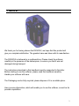
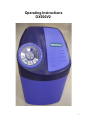
Operating Instructions
DX500V2
1
1 General;
We thank you for having chosen the DX500V2, we hope that this product will
give you complete satisfaction. The greatest care was taken with its manufacture.
The DX500V2 is delivered in a cardboard box. Please check the softener
carefully in the presence of the deliveryman, to ensure you that it was not
damaged during transport.
The instructions described in this handbook must be respected to the letter.
Before starting to use the softener, please read this handbook carefully.
Handle your softener with care.
The Packaging can be fully recycled, please dispose of it in a suitable place.
Here is some information, which will enable you to use the softener, as well as its
possible capabilities.
2
2 Presentation;
View of the Softener
Salt lid
Salt Storage
Control timer
Control Valve
Resin Tanks
Drain connections
By-pass (bronze option)
Raw water inlet
Treated water outlet
Flexible tubes (optional)
3
2 Presentation;
The valve alternates automatically between the service and regeneration cycles
BRINE DRAW
AND
SLOW RINSE
SALT TANK
REFILL
SERVICE
INDICATION OF THE
TANK IN SERVICE
With the valve in service, it is possible to change the time of day, the valve program, or initiate a regeneration.
Indicator:
Valve in service – diode
illuminated
Regeneration tonight –
diode flashing
Flow Indicator:
The diode flashes when
water is used
Chlorinator option:
Diode illuminated during
Chlorination
Program button
Regeneration
Initiation button
4
3 General Installation notes;
1 Pressure
A minimum pressure of 1,8 bar (30psi) is necessary in order that the valve regenerates
correctly. Do not exceed 8.0 bar (120 psi). If the case arises a pressure regulator must
be installed before the installation
2 Electrical connection
Make sure that the power supply cannot be cut by a switch upstream of the installation.
If the electric cable is damaged, a qualified person must replace it.
3 Existing plumbing
It must be in good condition and not furred up. In case of doubt, it is preferable to
replace it. The installation of a prefilter is always advised.
4 Water Temperature
The temperature of water should not exceed 35 °C and the installation should not be
subjected to freezing conditions (risk of very serious damage).
4 Installation notes;
When you choose the site for your DX500V2, please take into account the
following points and procedures:
1) To install your DX500V2 in the chosen place, ensure that the floor is clean, flat and
stable (If necessary, put a board under the softener to ensure a level area). There must
always be a drain tundish adjacent to where the softener is to be installed to allow the
regeneration water to run-off. A power socket protected by a RSB and suitably earth
bonded must be sited adjacent to the softener.
2) In cold weather, it is recommended that the DX500V2 be brought up to ambient
temperature before proceeding with the installation. The DX500V2 must positioned
so that it is protected from freezing. Do not install the unit where it is exposed to direct
sunlight or high temperatures (45 °C max).
3) Plumbing must be installed according to the local bylaws and regulations in force.
The size of the drain tube must be at least 13 mm (1/2").
5
4) The soldered joints on the principal plumbing and the connection to the drainpipe
must be carried out before the DX500V2 is connected to prevent any damage to the
softener. For all interventions, isolate the water supply at the stopcock and disconnect
the electrical supply.
5) Fill the salt reservoir with 50mm (2") water. Do not add salt for the moment.
6) Put the by-pass valve of your DX500V2 in the "by-pass" position. Open the raw
water feed tap and a cold water tap in the vicinity run for a few minutes until all of the
pipes are rinsed of any residual foreign bodies (solder remains). Turn off the raw water
feed tap and cold tap when water runs clear.
7) Put the by-pass valve in the "service" position and let the water run into the resin
tanks. When the water flow stops, open a cold-water tap and let run in order to purge
the air remaining in the resin tank. Repeat for the second resin tank.
8) Connect the softener electrically. Once powered, the valve may cycles itself and turn
over the position service.
9) The valve includes an indicator to inform the fitter of its position: the wheel directly
below the motor indicates the bottle that is currently in the service position. The Digital
display on the front of the softener alternates between the volume remaining in the tank
in service, the number of the tank in service (U-1 or 2 corresponds with the wheel:
INDICATION OFthe TANK IN SERVICE") and the time of the day.
Important: to understand various displays, please see the following
chapter: Programming.
10) Initiate a regeneration and bring the valve to cycle 1, by pressing the
regeneration button. The valve begins by transferring from one tank to the other and
then entering the regeneration cycle of the tank that was in service. The water runs until
the system is purged of the air. Once the air is completely evacuated, it enters the Brine
draw & slow rinse stage and then into brine refill. On return to the service position
repeat the procedure. This allows the complete purge of the second bottle.
11) The installation must be carried out under hygienic conditions. It is
recommended that annual maintenance be undertaken by qualified
personnel.
6
5 Programming;
1. Programming the time of day
Press the - or + keys to adjust the time of day per minute. Prolonged holding of
either the - or + keys will accelerate the changes.
2. Programming the valve
2.1. Enter the programming mode
Press and hold both of the - and + keys for 5 seconds to enter the programming
mode.
2.2. Change of program and modifications
Press the
key to pass from one stage to the next until leaving the program and
returning in service. To use the- or + keys to modify the programmed values.
The programmed values.
Note: it is necessary to pass through all of the programming stages and to return to
service position so that any modifications to the program are saved.
The first stage of the programming mode corresponds to
the system capacity. The capacity is expressed
in US gallons, litres or in m3 (format US/metric or m3). For
example: 6500 litres.
The second stage allows the adjustment of the time of
regeneration. For example: 2 O’clock in the morning.
The third stage is a calendar day override. (maximum
number of days between 2 regenerations). For
example: a regeneration at least every 7 days.
Press the
key to return to the service position.The programming is finished.
3. Initiate a manual regeneration
In the event of prolonged absence, and of non-use of your DX500V2, it is
necessary to initiate a manual regeneration.
7
There are two ways to initiate a manual regeneration:
1. To press the
key: if an immediate regeneration is programmed, the valve will
instantly start the regeneration.
2. To press and hold the
instantly.
key for 5 seconds: - in both cases, regeneration will start
6 Description of function;
Regeneration volumetric immediate
Under normal operation, the display alternates between the time of day, the volume
remaining and the tank in service, (U1 or U2). The volume display is in litres.
Progressively with the use, the volume remaining display decreases from the
maximum value down zero or (- - - -). When this occurs, regeneration is started
immediately. A water flow is indicated by the flow diode that flashes at a varying
speed according to the water flow. For example:
Volume remaining 530 litres
Volume remaining 0 litre
* For capacity figures please refer to Appendix A
Immediate volumetric regeneration with a calendar override
When the set number of days between each regeneration is reached, regeneration
is started immediately. Regeneration occurs whether or not the volume remaining
has reached zero.
8
Control during a regeneration
During regeneration, the valve will display the number of the regeneration cycle
stage to be reached (display flickering) or reached and remaining time for this cycle
(fixed display). Once all of the regeneration cycles are carried out, the valve returns
to the service position. For example:
The regeneration is in stage 2 with twenty-seven minutes
remaining.
To step from one cycle stage to the next during regeneration, press the key. This will
have no effect if the valve is already moving between two cycles.
Operation in programming mode
One can enter the programming mode only if the valve is in service. During the
programming mode, the valve still operates normally and records all information.
The valve program is stored in a non-volatile memory.
Operation during a power interruption.
During a power outage, all the data is saved to be restored once the power is
returned. The programmed data can be stored for years without loss. The
Electronics will be inoperative during power outage and any programmed
regeneration will be delayed. The Electronics restores all information from the
moment to which the power stopped. An incorrect time will indicate that there was a
power interruption.
9
7 Wiring Diagram;
Up Flow
Timer
24v 50/68Hz
HCAM
PWR VDC LED
METER H/S
SCAM
Valve
Motor
EM
NOIR
TRANSFORMER
PN 25651
10
7 Wiring Diagram;
Up Flow + Chlorinator
Timer
24v 50/68Hz
HCAM
PWR VDC LED
SCAM
METER H/S
CHLORINATOR
Valve
Motor
EM
NOIR
TRANSFORMER
PN 18355
11
8 Exploded Diagram;
Power Head – Up Flow (Ref: 28396)
12
8 Exploded Diagram;
Power Head – Up Flow (REF: 28396)
13
8 Exploded Diagram;
Power Head – Up Flow + chlorinator (ref: 28363)
14
8 Exploded Diagram;
Power Head – Up Flow + chlorinator (ref: 28363)
15
8 Exploded Diagram;
Valve Body Assembly (Ref: 28238)
16
8 Exploded Diagram;
Second tank adaptor assembly
17
8 Exploded Diagram;
Water meter ¾ assembly
18
9 Fault finding;
19
9 Fault finding;
If you note one of the problems quoted above, please contact your retailer.
20
10 Appendix A
Capacity setting at various hardness figures
21