1
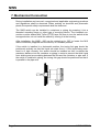
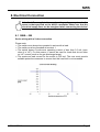
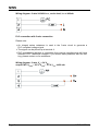
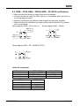
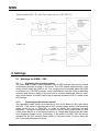
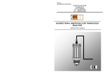
Operating Instructions
for
Level Switch
Tuning Fork Principal
Model: NWS
NWS
1. Contents
1.
2.
3.
4.
5.
6.
Contents ........................................................................................................ 2
Note .............................................................................................................. 3
Instrument Inspection .................................................................................... 3
Regulation Use.............................................................................................. 3
Operating Principle........................................................................................ 4
Use in Hazardous Areas (NWS-2E) .............................................................. 4
6.1 Device function .................................................................................... 4
6.2 General ................................................................................................ 5
6.3 Designation .......................................................................................... 5
6.4 Temperature resistance ....................................................................... 5
7. Mechanical Connection ................................................................................. 6
8. Electrical Connection .................................................................................... 7
8.1 NWS-...200 .......................................................................................... 7
8.2 NWS-...23/24; NWS-...2W/2H; NWS-...2E (ATEX certification) ........... 9
9. Settings ....................................................................................................... 10
9.1 Settings for NWS-...200.. ................................................................... 10
9.2 Settings for NWS-...23/24/2W/2H ...................................................... 12
9.3 Settings for NWS-...2E (ATEX certification) ....................................... 14
10. Technical Information .................................................................................. 15
11. Order Codes ............................................................................................... 17
12. Service and Maintenance ............................................................................ 17
13. Trouble Shooting ......................................................................................... 17
14. Recommended Spare Parts ........................................................................ 18
15. Disposal ...................................................................................................... 18
16. Dimensions ................................................................................................. 19
17. Declaration of Conformance ....................................................................... 21
Manufactured and sold by:
Kobold Messring GmbH
Nordring 22-24
D-65719 Hofheim/Germany
Tel.: +49(0)6192-2990
Fax: +49(0)6192-23398
E-mail: [email protected]
Internet: www.kobold.com
Page 2
NWS K05/0912
NWS
2. Note
Please read these operating instructions before unpacking and putting the unit
into operation. Follow the instructions precisely as described herein.
The devices are only to be used, maintained and serviced by persons familiar
with these operating instructions and in accordance with local regulations
applying to Health & Safety and prevention of accidents.
When used in machines, the measuring unit should be used only when the
machines fulfil the EWG-machine guidelines.
3. Instrument Inspection
Instruments are inspected before shipping and sent out in perfect condition.
Should damage to a device be visible, we recommend a thorough inspection of
the delivery packaging. In case of damage, please inform your parcel service /
forwarding agent immediately, since they are responsible for damages during
transit.
Scope of delivery:
The standard delivery includes:
• Level Switch
model: NWS
• Operating instructions
4. Regulation Use
Kobold model NWS Liquid-Level Switches are designed to be wired as 2-wire or
3-wire switches and can be universally installed in any position in containers and
piping. They can be used in many types of liquids including oils, water, paints and
varnishes, sauces, milk, carbonated liquids and foamy oils. The liquid may have a
maximum viscosity of 5000 cSt. At higher viscosities, the response time may
increase. NWS Liquid-Level Switches are ideally suited for use in hygienic and
sterile applications and designed to withstand CIP cleaning methods at temperatures up to 150 °C.
Any use of the device which exceeds the manufacturers specification may
invalidate its warranty. Therefore any resulting damage is not the responsibility of
the manufacturer. The user assumes all risk for such usage.
NWS K05/0912
Page 3
NWS
5. Operating Principle
The KOBOLD liquid level switch NWS is designed as a 2 and 3-wire switch and
can be universally used in vessels and pipelines. The NWS operates on the
tuning fork principle in air at resonance frequency. A piezoelectric crystal is used
for excitation of oscillations and for monitoring the actual oscillation frequency.
When the fork is immersed in liquid, the frequency changes: this change is
detected electronically and the output signal is changed. The NWS operates as a
two-wire switch in series with the load. The simple electronic switch is operated
by the liquid. The NWS can also be connected to a PLC through a third terminal.
Special Features:
The NWS has a switch status indicator with LED, which can be seen continuously
through a lens in the cover. The LED flashes approximately once every second,
when the NWS has switched off and goes onto a permanent light, when the NWS
is switched on. The LED is a visible confirmation that the NWS is working
correctly and that the condition of the wet side is correctly indicated. With a
selector switch the NWS can be set either as an upper limiter or as a lower
limiter.
6. Use in Hazardous Areas (NWS-2E)
6.1 Device function
The intrinsically safe NAMUR oscillating fork sensor is used to detect the fill
levels of combustible and non-combustible liquids. The sensor is supplied with
current from a switching amplifier with an intrinsically safe output circuit in
accordance with the NAMUR specification and behaves accordingly when the
oscillating fork is dampened by liquid or can oscillate freely. The sensor can be
used in all zones in gaseous hazardous areas.
Page 4
NWS K05/0912
NWS
6.2 General
The devices may be installed in zones 0, 1 and 2. The intrinsically safe circuits
must be installed (by specialists) in conformance with the applicable installation
requirements (certification document of installer, protected routing of the
intrinsically safe circuits, etc.).
The devices are constructed in accordance with protection type IP 65. If
applicable, they must be protected against adverse environmental conditions.
The EU model test certificates must be complied with. Any “special regulations”
contained in them must be followed.
The device should only be used for its intended use.
The connection with the associated and/or intrinsically safe equipment must be
separately checked.
The sensors must be grounded to discharge accumulated electrostatic charge.
At an ambient temperature area of -5 .. 70 °C the connected electrical cable may
be mechanically moved. Furthermore at an ambient temperature area of
- 20 .. + 70 °C the electrical cable must be mounted in a fixed and static manner.
6.3 Designation
Model: NWS***2E* ****
II 1 G EEx ia IIC T6
BVS 03 ATEX E 119
DMT 0158
Production-No.: SN: E999999 (consecutively numbered)
6.4 Temperature resistance
The values for ambient temperatures ranging from -20 °C up to the values
indicated in the following table apply to this sensor, depending on the max.
temperature of the oscillating forks in the sensor:
Ambient temperature
Medium temperature
Temperature class
NWS K05/0912
70 °C
75 °C
T6
70 °C
90 °C
T5
Page 5
NWS
7. Mechanical Connection
During installation and removal, recognised and applicable engineering practices
and regulations shall be observed. When working on electrical and pneumatic
plants, the special safety requirements shall be observed.
The NWS switch can be installed in containers or piping by screwing it into a
threaded mounting flange or other type of mounting device. The threaded connection must be sealed with Teflon (PTFE) tape. Be sure to turn the switch at the
hexagonal drive; do not install the switch by turning it at the housing.
After installation, the NWS-...200 can be rotated up to 330° to locate the M16
cable connection (supplied with the device) in a suitable position.
If the switch is installed in a horizontal position, the tuning fork gap should be
positioned vertically so that the liquid can drain from it. If the liquid being monitored is of high viscosity, the switch should be installed so that it extends the
maximum distance into the container or piping in order to prevent the thick liquid
from sticking and accumulating between the fork and the container or pipe wall. If
the switch is installed in piping, the tuning fork gap should be positioned so that it
is parallel to the pipe axis.
Page 6
NWS K05/0912
NWS
8. Electrical Connection
Attention! Be sure that the supply voltage of your system is the
same as that specified on the device nameplate. Make sure that the
electrical supply lines are de-energised when connecting the device!
8.1 NWS-...200
Series wiring with a 2-wire connection
Please note:
• The switch must always be operated in series with a load.
• The switch must be grounded at terminal 1.
• The switch draws a continuous operating current of less than 3.5 mA (even
when it is "off"). For this reason, it cannot be used for loads that do not allow
an “off” current (such as for gas discharge lamps).
• The maximum load current for the switch is 500 mA. The user must provide
suitable protective measures to ensure that this load limit is not exceeded.
NWS K05/0912
Page 7
NWS
Wiring diagram: 2-wire 24-240VAC/DC, series load, Imax ≤ 400mA
PLC connection with 3-wire connection
Please note:
• An integral series resistance is used in the 3-wire circuit to generate a
PLC-compliant voltage signal.
• The signal can be picked up at terminal 4.
• PLC programming devices or computers from various manufacturers will have
different "OFF" threshold voltages. If you should have problems with this setting, please contact us for assistance.
Wiring diagram: 3-wire, VS = 24 VDC,
output PNP: UHIGH ~ 20 V; ULOW ~ 3.5 V; Imax ≤ 400 mA
Page 8
NWS K05/0912
NWS
8.2 NWS-...23/24; NWS-...2W/2H; NWS-...2E (ATEX certification)
• Make sure that the electrical supply lines are de-energised.
• Connect the device using the M12x1 plug or a connection cable as shown in
the wiring diagram below.
• Matching connectors with different cable lengths are optionally available.
• Make sure that the installation is properly performed and that the IP protection
level is maintained.
Wiring diagram NWS-...23/24 (24 VDC)
Wiring diagram NWS-...2W/2H
2
GND (n.c.)
1 +Vs (n.o.)
3
Switch
4 Out
+Vs (n.c.)
GND (n.o.)
2
1 +Vs
3
Switch
4 Out
GND
Wiring diagram NWS-...2E.. (NAMUR, ATEX)
E
2
1
3
4
-S
+S (n.o.)
+S (n.c.)
Cable pin assignment
Strand colour
brown
blue
black
NWS-...23/24
+Vs(n.o.) / GND
GND / +Vs (n.c.)
Switch Out
Lead-/Pinnumber
NWS-...2E
1
2
3
4
+S (n.o.)
ground
-S
+S (n.c.)
NWS K05/0912
NWS-...2W/2H
+Vs
GND
Switch Out
Page 9
NWS
9. Settings
9.1 Settings for NWS-...200..
9.1.1
Signalling the operating status
The NWS has an output status indicator with an LED monitor that can be viewed
continuously through a lense in the cover. The LED flashes approximately once
every second when the NWS is off. It is continuously illuminated when the NWS
is switched on. The LED provides visual confirmation that the NWS is operating
correctly and that the status of the wet side is correctly displayed. With its operating mode switch, the NWS can be set to operate as either an N/C contact or an
N/O contact.
9.1.2
Operating mode selector switch
The operating mode switch is positioned on the circuit board on the right about
the LED. If the switch is operated as an N/C contact (upper limiter), the operating
mode must be set to DRY-ON, in order to obtain the maximum fail-safe
behaviour. The device completes the circuit in the dry state (empty state) so that
a fault at the device or in the wiring results in a voltage drop that causes an alarm
to be triggered (break circuit). Conversely, if the switch is to WET-ON, the device
operates as an N/O contact (lower limiter) in fail-safe mode, in which case the
fork is normally immersed in liquid.
Page 10
NWS K05/0912
NWS
9.1.3
Calibration mode
Each appliance is adjusted by the
factory to record fluids with density 1,0
kg/l (water). It is not usually necessary
to alter this pre-adjustment. In extreme
situations, however, such as with very
light fluids at high temperatures or
highly viscous fluids, which produce a
significantly extended reaction time from
dry to wet, it can be advantageous to
alter the pre-adjustment. In order to
attain the calibration mode the Setup
button must be activated and held, then
the supply voltage must be switched on.
After approximately 1 second the LED
goes on, after 2 seconds the LED goes
out, then let go of the Setup button – the
appliance stays now in the main menu
of the calibration mode.
There is a choice of options in the main menu - Switchpoint Calibration,
Hysteresis Level and LED Mode. The LED indicates the selected option:
• Switchpoint Calibration: LED flashes briefly 1x, then LED 2 seconds off.
• Hysteresis Level: LED flashes briefly 2x, then LED 2 seconds off.
• LED Mode: LED flashes briefly 3x, then LED 2 seconds off.
The option points are repeated in an infinite loop.
In order to get access to an option the Setup button must be activated briefly
when the LED has signalled the requested option point.
Switchpoint Calibration:
The "Switchpoint Calibration Mode" is signalled by: LED 1x briefly off, then LED 2
seconds on.
Dip the tuning fork as far as the required switchpoint (1/2 – 2/3 of the fork length)
in the medium and activate the Setup button. The calibration is made.
A successful calibration is signalled by the LED flashing quickly three times.
Hysteresis and LED Mode are set back to default! After calibration the switch
back to the main menu takes place.
Hysteresis Level:
The "Hysteresis Level Mode" is signalled by: LED 2x briefly off, then LED 2
seconds on. Briefly activate the Setup button to get to the submenu.
• Hysteresis Level 1(approx. 1-1.5mm): LED flashes briefly 1x, then LED 2
seconds off.
• Hysteresis Level 2 (approx. 3-4.5mm, Standard): LED flashes briefly 2x, then
LED 2 seconds off.
• Hysteresis Level 3 (approx. 5-7.5mm): LED flashes briefly 3x, then LED 2
seconds off.
NWS K05/0912
Page 11
NWS
The choice of options is repeated in an infinite loop. To select an Hysteresis
Level, the Setup button must be activated after the flashing of the relevant LED.
Three quick flashes of the LED signal that an option has been selected, then the
switch back to the main menu is made.
LED Mode:
The "LED Mode" is signalled by: LED briefly 3x off, then LED 2 seconds on.
Briefly activate the Setup button in order to attain the option menu LED Mode.
• LED Mode 1 (Standard): LED flashes briefly 1x, then LED 2 seconds off. LED
shows the status of the switch output
• LED Mode 2: LED flashes briefly 2x, then LED 2 seconds off. LED indicates
whether the tuning fork is wetted or not
The choice of options is repeated in an infinite loop. In order to select an "LED
Mode" the button must be briefly activated after the relevant flashing of the LED.
Three quick flashes of the LED signal that an option has been selected. When the
LED Mode has been successfully selected, the switch back to the main menu is
made.
In order to leave the calibration mode, the appliance must be separated from the
voltage supply for approx. 10 seconds
9.1.4
Test Function NWS-20
Through the pressing and holding of the setup button, independent of the state of
NWS, the switching output can be temporarily switched off.
During the test phase, the LED blinks rapidly.
Releasing the button returns the NWS after ca. 3 sec. to the current operating
condition.
9.2 Settings for NWS-...23/24/2W/2H
9.2.1
Signalling the operating status
The NWS has an output status indicator with an LED monitor that can be viewed
continuously through a lense in the cover. The LED flashes approximately once
every second when the NWS is off. It is continuously illuminated when the NWS
is switched on. The LED provides visual confirmation that the NWS is operating
correctly and that the status of the wet side is correctly displayed. With its operating mode switch, the NWS can be set to operate as either an N/C contact or an
N/O contact.
9.2.2
Selecting operating mode
By reversing the polarity of the power supply, the switching function of the NWS...23/24 can be changed from an N/C contact to an N/O contact.
In the case of the NWS-...2W/2H (WHG), the switching function cannot be
changed for reasons of safety. This electronic switch opens in case of wetting, a
faulty sensor or a power failure.
9.2.3
Calibration mode
Each appliance is adjusted by the factory to record fluids with density 1,0 kg/l
(water). It is not usually necessary to alter this pre-adjustment. In extreme
Page 12
NWS K05/0912
NWS
situations, however, such as with very light fluids at high temperatures or highly
viscous fluids, which produce a significantly extended reaction time from dry to
wet, it can be advantageous to alter the pre-adjustment. In order to attain the
calibration mode the test magnet must be placed at the label marking and held,
then the supply voltage must be switched on. After approximately 1 second the
LED goes on, after 2 seconds the LED goes out, then remove the test magnet –
the appliance stays now in the main menu of the calibration mode.
There is a choice of options in the main menu - Switchpoint Calibration,
Hysteresis Level and LED Mode. The LED indicates the selected option:
• Switchpoint Calibration: LED flashes briefly 1x, then LED 2 seconds off.
• Hysteresis Level: LED flashes briefly 2x, then LED 2 seconds off.
• LED Mode: LED flashes briefly 3x, then LED 2 seconds off.
The option points are repeated in an infinite loop.
In order to get access to an option the test magnet must be placed briefly when
the LED has signalled the requested option point.
Switchpoint Calibration:
The "Switchpoint Calibration Mode" is signalled by: LED 1x briefly off, then LED 2
seconds on.
Dip the tuning fork as far as the required switchpoint (1/2 – 2/3 of the fork length)
in the medium and activate by placing the test magnet briefly. The calibration is
made.
A successful calibration is signalled by the LED flashing quickly three times.
Hysteresis and LED Mode are set back to default! After calibration the switch
back to the main menu takes place.
Hysteresis Level:
The "Hysteresis Level Mode" is signalled by: LED 2x briefly off, then LED 2
seconds on. Activate by placing the test magnet briefly to get to the submenu.
• Hysteresis Level 1(approx. 1-1.5mm): LED flashes briefly 1x, then LED 2
seconds off.
• Hysteresis Level 2 (approx. 3-4.5mm, Standard): LED flashes briefly 2x, then
LED 2 seconds off.
• Hysteresis Level 3 (approx. 5-7.5mm): LED flashes briefly 3x, then LED 2
seconds off.
The choice of options is repeated in an infinite loop. To select an Hysteresis
Level, the test magnet must be placed briefly after the flashing of the relevant
LED. Three quick flashes of the LED signal that an option has been selected,
then the switch back to the main menu is made.
LED Mode:
The "LED Mode" is signalled by: LED briefly 3x off, then LED 2 seconds on.
Briefly activate the Setup button in order to attain the option menu LED Mode.
• LED Mode 1 (Standard): LED flashes briefly 1x, then LED 2 seconds off. LED
shows the status of the switch output
• LED Mode 2: LED flashes briefly 2x, then LED 2 seconds off. LED indicates
NWS K05/0912
Page 13
NWS
whether the tuning fork is wetted or not
The choice of options is repeated in an infinite loop. In order to select an "LED
Mode" the test magnet must be placed briefly after the relevant flashing of the
LED. Three quick flashes of the LED signal that an option has been selected.
When the LED Mode has been successfully selected, the switch back to the main
menu is made.
In order to leave the calibration mode, the appliance must be separated from the
voltage supply for approx. 10 seconds
9.2.4
Test function
The magnet supplied with the device can be used to switch off the electrical
output of the NWS- independent of status of the tuning fork. In this case, the
magnet must be placed on the location indicated on the device nameplate. After
approximately 2 seconds, the NWS- switches the output off and the LED begins
blinking. After the magnet is removed, the output returns after 3 seconds to its
previous state.
9.3 Settings for NWS-...2E (ATEX certification)
9.3.1
Signalling the operating status
Function
N/C
N/O
Signalling
LED on
LED flashes quickly
LED on
LED flashes quickly
NAMUR-output
≥ 2.1 mA
≤ 0.8 mA
≥ 2.1 mA
≤ 0.8 mA
fork
uncovered
covered
covered
uncovered
9.3.2
Selecting operating mode
The choice of plug connector or cable pin assignment determines whether the
level switch is operated as an N/C contact or an N/O contact (see the section
“Electrical connection” below).
9.3.3
Calibration mode
Each NWS-2E is adjusted by the factory to record a multitude of different fluids. It
is not possible to alter this pre-adjustment.
Page 14
NWS K05/0912
NWS
10. Technical Information
Fork:
Process connection:
Electronic housing:
Process connections:
Protection:
Max. operating pressure:
Max. medium temp.:
Min. medium density
Ambient temperature:
Power supply
NWS-...200..:
NWS-...23/24/2W/2H..:
NWS-...2E..(ATEX):
Delay:
Viscosity:
Hysteresis:
Repeatability:
Weight:
NWS K05/0912
stainless steel 1.4404
stainless steel 1.4404
NWS-...200: PAG, glass-fibre-reinforced
cover with window, 330° rotatable
all other types:
stainless steel 1.4301
Pipe thread DIN EN 10226-1,
NPT thread, Tri-Clamp,
Pipe connection DIN 11851
(sanitary connection),
Aseptic-connection DIN 11864,
DRD flange,
Flange B 25 PN 40 DN 2527,
Flange B 50 PN 40 DN 2527,
Flange ANSI B 16.5 - 1", 300 lbs,
Flange ANSI B 16.5 - 2", 300 lbs
plastic housing: IP 65
(NWS-...200)
stainless steel housing, plug connection: IP 67
stainless steel housing, cable connection: IP 68
45 bar
Flange connection: see pressure steps
130 °C (NWS-..200..)
90 °C (for all other NWS)
short-time 150 °C for CIP
(valid for all models NWS)
0.8 kg/L (lower on request)
-20 °C...+70 °C
24...240 VDC/ AC (50/ 60 Hz);
2-wire; 24 VDC, 3-wire
24 VDC, 3-wire
Isolation Switching Amplifier to IEC 60947-5-6
(Namur) necessary (for example: REL-6)
1 s wet /dry
1 s dry / wet
5000 mm2/s max. at 25 °C
(influence on the response time)
4 mm vertical, 1 mm horizontal
± 1 mm at ambient temperature
0.5 kg (for R ¾ and ¾ NPT)
Page 15
NWS
Electrical Connection:
NWS-...200...:
cable connection: M 16 x 1.5
terminal: max. 1.5 mm2 (26-14 AWG)
capacity: 0.4 A max. at room temp.
min. switching current: 7.5 mA
leakage current in off-state: < 3.5 mA constant
voltage drop: ca. 6 V (2-wire connection)
NWS-...23/24/2W/2H..:
connector M12x1, 4-pole or 1.5 m
fixed cable, 3-pole
switching output: O. C. PNP or NPN (factory
set), max. 300 mA, short-circuit-proof
contact function: N/C or N/O adjustable
by switching polarity of supply voltage
(only NWS...23/24)
Overload cut-off (NWS-2x):
In case of thermal overload or excessive current,
the unit cust off the load. The triggering of
overload protection is indicated by fast blinking of
the LED.
NWS-...2E.. (ATEX):
connector M12x1, 4-pole or 1.5 m cable
2-wire NAMUR output
N/C or N/O selectable
N/C:
≥ 2.1 mA discovered
≤ 0.8 mA covered
N/O:
≤ 0.8 mA discovered
≥ 2.1 mA covered
Page 16
NWS K05/0912
NWS
11. Order Codes
Example: NWS-R20 20 0 0000
Connection
R ¾ male thread
R 1 male thread
¾ NPT male thread
1 NPT male thread
DIN-flange DN 25
DIN-flange DN 50
1“ ANSI-flange
2“ ANSI-flange
Tri-Clamp DN 40
Tri-Clamp DN 50
Sanitary DN 40 (DIN 11851)
Sanitary DN 50 (DIN 11851)
Aseptic connection
DN 50 (DIN 11864)
DRD Ø 125 mm flange
Model
NWS-R20...
NWS-R25...*
NWS-N20...
NSW-N25...*
NWS-F25...
NWS-F50...*
NWS-A25...
NWS-A50...*
NWS-T40...
NWS-T50...
NWS-L40...
NWS-L50...
Special connection
NWS-YYY...
NWS-H50...
NWS-D1Z...
Electrical connection
Plastic housing
200 = 24...240 VAC/DC
cable gland/terminal connect.
St. steel housing/plug connect.
23S = 24 VDC, PNP, plug M12x1
24S = 24 VDC, NPN, plug M12x1
2WS*** = 24 VDC, WHG, PNP, plug M12x1
2HS*** = 24 VDC, WHG, NPN, plug M12x1
2ES = ATEX-approval, plug M12x1
St. Steel housing/cable connect.
23F = 24 VDC, PNP, 1.5 m cable
24F = 24 VDC, NPN, 1.5 m cable
2WF*** = 24 VDC, WHG, PNP, 1.5 m cable
2HF*** = 24 VDC, WHG, NPN, 1.5 m cable
2EF = ATEX-approval, 1.5 m cable
Sensor version
0060 = 60 mm (only for
NWS-T / NWS-L / NWS-H)
0070 = 70 mm
standard version, short
(not for NWS-T / NWS-L)
0117** = 117 mm
extended
0300** = 300 mm sensor
0500**= 500 mm sensor
1000** = 1000 mm sensor
XXXX** = please specify
special length 4-position
in mm (max. 3000 mm)
**only models marked with *are available with sensors in extended version.
***WHG-approval in preparation.
12. Service and Maintenance
The functional behaviour of these devices is stable, even over long periods or
time. Regular adjustments or similar procedures are not required. No
maintenance of any type is required.
In the event that device faults are noted, this device should be immediately
removed from service. The device contains no user-serviceable parts. Return the
device to the manufacturer for examination.
13. Trouble Shooting
Devices that are operated in hazardous areas must not be modified in any way.
Repairs must be performed by trained, qualified service personnel only. Defective
devices should normally be returned to the manufacturer for examination.
NWS K05/0912
Page 17
NWS
14. Recommended Spare Parts
There are no recommended spare parts.
If the device becomes defective, it usually means that there is a fault in the device
electronics that must be diagnosed and repaired.
In this case, we recommend that the device be returned to the manufacturer for
servicing.
15. Disposal
Disposal of packaging and used parts shall be done in conformance with the
regulations of the country in which the device is installed.
Page 18
NWS K05/0912
NWS
16. Dimensions
NWS-...200
24...VAC/DC
Plastic housing
NWS-...23S/24S
NWS-...2WS/2HS
24 VDC
Plug connection
NWS-...23F/24F
NWS-...2WF/2HF
24 VDC
Terminal connection
Ø 40
65
70
Ø 40
NWS-...2ES
ATEX
Plug connection
NWS K05/0912
NWS-...2EF
ATEX
Cable connection
Page 19
NWS
NWS-R20/N20
(Standard, short)
NWS-R25/N25
NWSN25...0117
(Standard, long)
NWS-F../NWS-A..
Flange version
DN 25 /PN 40
DN 50 / PN 40
ANSI 1“ 300 lbs
ANSI 2“ 300 lbs
L2
18
20
17,5
22,4
NWS-L..
Sanitary connection
(DIN 11851)
Page 20
NWS-T..
Tri-clamp
L3
approx. 47
approx. 95
approx. 41
approx. 92
NWS-H..
Aseptic connection
(DIN 11864)
NWS K05/0912
NWS
17. Declaration of Conformance
We, KOBOLD Messring GmbH, Hofheim-Ts, Germany, declare under our sole
responsibility that the product:
Level Switch
model: NWS -..
to which this declaration relates is in conformity with the standards noted below:
EN 61010-1
2002
EN 61326-A2
2006
Additional for model NWS-***2E* ****
EN 50014: 1997 + A1 – A2
EN 50020: 1994
EN 50284: 1999
Also the following EEC guidelines are fulfilled:
2004/108/ EC (Electromagnetic compatibility)
2006/95/EC (Low voltage guideline)
94/9/ECEquipment and Protective systems intended for
use in a potentially Explosive Atmospheres (ATEX 100a)
Quality Management Production
Certificate number: BVS 09 ATEX ZQS/E110
Notified body: DEKRA Exam GmbH
Identification number: 0158
Hofheim, 30. Sep. 2010
H. Peters
General Manager
NWS K05/0912
M. Wenzel
Proxy Holder
Page 21
NWS
Page 22
NWS K05/0912
NWS
NWS K05/0912
Page 23
NWS
Page 24
NWS K05/0912