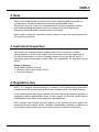
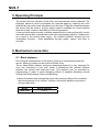
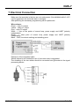
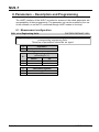
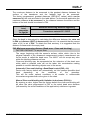
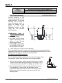
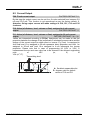
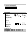
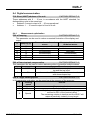
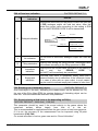
1
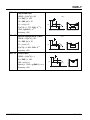
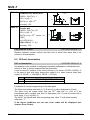
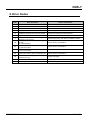
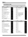
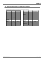
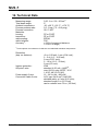
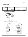
Instruction Manual for Ultrasonic Level Meter Model: NUS-7... NUS-7 1. Contents 1. 2. 3. 4. 5. 6. Contents ........................................................................................................ 2 Note .............................................................................................................. 3 Instrument Inspection .................................................................................... 3 Regulation Use.............................................................................................. 3 Operating Principle........................................................................................ 4 Mechanical connection .................................................................................. 4 6.1 Block distance ...................................................................................... 4 6.2 Installation (Liquid Level Measurement) .............................................. 5 6.3 Installation (Open Channel Flow Measurement) .................................. 6 7. Electrical Connection .................................................................................... 7 8. Parameters – Description and Programming ................................................ 8 8.1 Measurement configuration ................................................................. 8 8.2 Current Output ................................................................................... 13 8.3 Relay Output ...................................................................................... 14 8.4 Digital communication ........................................................................ 15 8.4.1 Measurement optimisation ....................................................... 15 8.5 32-Point linearisation ......................................................................... 24 8.6 Informational parameters (read out parameters) ............................... 25 8.7 Additional parameters of the flow metering ........................................ 26 9. Error Codes ................................................................................................. 27 10. Parameter Table ......................................................................................... 28 11. Sound Velocities in Different Gases ............................................................ 29 12. Technical Data ............................................................................................ 30 13. Order Codes ............................................................................................... 31 14. Dimensions [mm] ........................................................................................ 31 15. Declaration of Conformance ....................................................................... 32 Manufactured and marketed by: Kobold Messring GmbH Nordring 22-24 D-65719 Hofheim Tel.: 06192-2990 Fax: 06192-23398 Internet: http: //www.kobold.com e-mail: [email protected] Seite 2 NUS-7 K01/1014 NUS-7 2. Note Please read these operating instructions before unpacking and putting the unit into operation. Follow the instructions precisely as described herein. The devices are only to be used, maintained and serviced by persons familiar with these operating instructions and in accordance with local regulations applying to Health & Safety and prevention of accidents. When used in machines, the NUS should be used only when the machines fulfil the EC-machine guidelines. 3. Instrument Inspection Instruments are inspected before shipping and sent out in perfect condition. Should damage to a device be visible, we recommend a thorough inspection of the delivery packaging. In case of damage, please inform your parcel service / forwarding agent immediately, since they are responsible for damages during transit. Scope of delivery: The standard delivery includes: Ultrasonic level meter model: NUS-7 Instruction Manual 4. Regulation Use NUS-7 is a rugged, high performance ultrasonic level measurement transmitter, having transducer and processing electronics incorporated in one single housing. Level measurement technology based on the non-contacting ultrasonic principle is especially suited for applications where, for any reason, no physical contact can be established to the surface of the material to be measured. Such reasons may include corrosive attack by the process medium against the measuring device material (acids), possible contamination (sewage) or particles of the process medium adhering to the measuring device (adhesive materials). NUS-7 K01/1014 Seite 3 NUS-7 5. Operating Principle The sensor emits an ultrasonic pulse train and receives the echoes reflected. The intelligent electronic device processes the received signal by selecting the echo reflected by the surface and calculates from the time of flight the distance between the sensor and the surface. A Norm signal output is available for remote transfer whereas a relay contact is available for monitoring purpose. A narrow beam angle ensures a reliable measurement in narrow silos with uneven side walls as well as in process tanks with various protruding objects. Furthermore, as a result of the narrow beam angle - the emitted ultrasonic signals have an outstanding focusing - deep penetration through gases, vapour and foam is ensured. 6. Mechanical connection 6.1 Block distance Due to signal characteristics of the sensor, there is an area directly below the sensor, where no pulses can be received (Dead Zone). The so called Block distance (minimum measuring distance) is very important for error free functioning of the level meter. It determines the minimal distance between the sensor and maximum level. This distance can be extended by programming in order to avoid disturbing effects of possible disturbing echoes coming from fixed objects (Close-end Blocking). Mount the sensor high enough that even with maximum filling of the container, the block distance is not violated. Violation of the block distance may lead to device-malfunction. Model NUS-7006 Seite 4 Block distance 0.25 m NUS-7 K01/1014 NUS-7 6.2 Installation (Liquid Level Measurement) Never mount two ultrasonic level-measuring devices in one container, because the two devices can interfere with each other's functioning. POSITION The optimal position of the NUS-4 is on the radius r = (0.3 … 0.5) R of the (cylindrical) tank / silo. (Take also sonic cone on page 39 into consideration.) SENSOR ALIGNMENT The sensor face has to be parallel to the surface of the liquid within 2-3. TEMPERATURE Make sure that the transmitter will be protected against overheating by direct sunshine. OBSTACLES Make sure that no inflow path or objects (e.g. cooling pipes, ladders, bracing members, thermometers, etc.) or no tank wall of the ragged surface protrude into the sensing cone of the ultrasonic beam. One fix object in the tank / silo that disturb the measurement can be blocked out by the optional programming unit. FOAM Foaming of the liquid surface may render ultrasonic level metering impossible. If possible, a location should be found, where foaming is the least (device should be located as far as possible from liquid inflow) or a stilling pipe or well should be used. WIND Intensive air (gas) movements in the vicinity of the ultrasonic cone is to be avoided. A strong draft of wind may "blow away" the ultrasound. Devices with lower measuring frequency (40, 20 kHz) are recommended. NUS-7 K01/1014 Sunshade FUMES / VAPOURS For closed tanks containing chemicals or other liquids, which creats fume/gases above the liquid surface especially for outdoor tanks exposed to the sun, a strong reduction of the nominal measuring range of the ultrasonic device is to be considered during device selection. Devices with lower measuring frequency (40, 20 kHz) are recommended in these cases units. Seite 5 NUS-7 L Dmin 150 Ø 60 200 Ø 65 250 Ø 75 450 - 6.3 Installation (Open Channel Flow Measurement) For ultimate accuracy, install the sensor as close as possible above the expected maximum water level (see minimum measuring range). Install the device in a place defined by the characteristics of the metering channel along the longitudinal axis of the flume or weir. In some cases foam may develop on the surface. Make sure that the surface, opposite to the sensor remain free of foam for proper sound reflection. From the point of view of measurement accuracy the length of the channel sections preceding and following the measuring flume and their method of joining to the measuring channel section are of critical importance. Despite of the most careful installation, the accuracy of flow metering will be lower than that of specified for the distance measurement. It will be determined by the features of the flume or weir applied. Seite 6 NUS-7 K01/1014 NUS-7 7. Electrical Connection Make sure the terminals in the box are not under power (Use shielded cable 6 x 0.5 mm2 suggested in the technical data or stronger). After powering the necessary programming can be performed. Wire colours: Green – relay C1 output Yellow – relay CC output Grey – relay C2 output White – I, one of the points of current loop, power supply and HART (polarity independent) Brown – I, other point of current loop, power supply and HART (polarity independent) Black – GND, functional earthing and shielding point Extension of the integrated cable: Should extension be needed the use of connection box is suggested. The shielding of the two cables should be connected and grounded at the signal processing device. NUS-7 K01/1014 Seite 7 NUS-7 8. Parameters – Description and Programming The HART interface of the NUS-7 provides for access to the whole parameter set and possibility of their programming. The parameter set can be reached by the use of the software run on the PC connected through HART modem to the loop. 8.1 Measurement configuration P00: c b a Engineering Units FACTORY DEFAULT: 000 Programming of this parameter will result in loading the factory default with the corresponding engineering units. Therefore all parameters should be set again! a 0 0 1 Engineering units (according to “c”) Metric US m ft cm inch c 0 1 Calculation system metric US b Seite 8 Operation Liquid level measurement NUS-7 K01/1014 NUS-7 FACTORY DEFAULT: 11 P01: 1 a Measurement Mode Parameter value „a” will determine the basic measurement value that will be transmitted. Subsequently values for the relays are also relating to these quantities. a Transmitted value Display symbol Distance DIST LEV LEV% VOL VOL% FLOW Level Volume Flow A 0 1 2 3 4 5 Measurement mode Distance Level Level % Volume Volume % Flow DIST H P11 P10 DIST 0 0 H Xm D LEV 0 H LEV % [%] 100 LEV%= DIST Parameters to set P00 P01(a) 0 P05 ≥ LEV=H-DIST LEV* P00 P01(a) = 1 P04 = H P05 ≥ Xm = Xm P11 P10 P10 H Xm P00 P01(a) 2 P04 = P05 ≥ P10 = P11 = = H Xm X 0% X100% A Transmitted value H DIST P11 P10 0 NUS-7 K01/1014 B C VOL D 0 100 Seite 9 VOL% [%] NUS-7 VOL%= VOL fP40…P45(H-DIST) Transmitted value Parameters to set VOL * P00 P01(a) = 3 P02(b) P04 = H P05 ≥ Xm P40…P45 P11 P10 P10 HX m P00 P01(a) = 4 P02(b) P04 = H P05 ≥ Xm P10 = X 0% P11 = X100% P40…P45 A: Shortest measurable distance B: Volume (content) pertaining to the greatest measurable level C: Whole value of the vessel D: diagram valid for the default value of P10 P11 P02:- c b a Calculation units FACTORY DEFAULT: 000 a Temperature °C 0 °F 1 This table is interpreted according to P00(c), P01(a) and P02(c) and is irrelevant in case of percentage measurement [ P01(a)= 2 or 4 )] b 0 1 Volume Metric US 3 m ft3 litre gallon c 0 1 2 3 Time s min hour day Weight (set also P32) Metric US lb (pound) tons tonnes Volume flow Metric US 3 3 m /time ft /time litre/time gallon/ time Attention! NUS-7 is a level transmitter. Although it can be used for measuring weight, due to factors involved in doing so, accuracy may essentially be influenced. P04:-Maximum Distance to be Measured (H) FACTORY DEFAULT: XM as per chart This is the only parameter that has to be programmed for each application other than distance (however to avoid disturbing effect of possible multiple echoes it is suggested to do this in distance measurement applications too). Seite 10 NUS-7 K01/1014 NUS-7 The maximum distance to be measured is the greatest distance between the surface of the transducer and the farthest level to be measured. The factory programmed, greatest distances (DEFAULT values) which can be measured by the units are listed in the table below. For the actual application the maximum distance to be measured i.e. the distance between the sensor and the bottom of the tank should be entered in P04. NUS-7 Level transmitter for liquids NUS-7 Maximum measuring distance XMm/feet Transducer material PP / PVDF 6/20 Since the level is determined by calculating the difference between the value set in P04 and distance (DIST) is measured by the unit, it is essential that the correct value of (H) is set in P04. To obtain the best accuracy it is suggested that this distance is measured in the empty tank. P05: Minimum measuring distance (Dead zone - Close-end blocking) FACTORY DEFAULT: Xm as per chart The range, beginning with the sensor’s surface, within which (due to the physical restraint of the ultrasound measurement system) measurement can not be made, is called the dead zone. The NUS-7 will not accept any echo within the blocking distance set here. Close-end blocking may be represented as the extension of the dead zone within which a possible echo will not be taken into consideration making possible to exclude disturbing objects near to the sensor. Automatic Close-end blocking =Dead Band control (P05 = Xm) Device with factory default will automatically set the smallest possible dead band depending on the conditions of the operation. This will be under optimal conditions a bit smaller in unfavourable circumstances greater than value given in the chart. Manual Close-end-blocking with limitation ≥ dead zone (P05>Xm) By entering a value, higher than the factory default the close-end blocking will be either the value programmed in P05 or the actual dead zone distance (influenced by the actual conditions of the application) whichever is greater. NUS-7 K01/1014 Seite 11 NUS-7 Minimum measuring distance Xm m/feet Sensor material PP / PVDF 0.25/0.82 FACTORY DEFAULT: 0 4mA Far-end blocking is the range below the level set in parameter P06. The far-end blocking can be used to avoid disturbing effect of stirrer or heaters at the bottom of the tanks. Detecting echoes in this range the unit provides special signals. 20mA P06: Far-end blocking P06=X SUB 0 X/8 A.) Measuring level or content Level sinking below the value of P06 current output is according to the value of the far-end blocking and further below SUB 0 (7/8 of P06) the ERROR CODE 10 will be transmitted via HART Level rising over value of far-end blocking: The calculation of level and volume will be based on the programmed tank dimensions, therefore the measured or calculated process values will not be influenced in any way, by the far end blocking value. H NUS-7 for liquids NUS-7 B.) Open channel flow metering Far-end blocking will be used for those small levels below which the accurate volume flow calculation is no longer possible. Level in the flume/weir sinking below the blocked out range: - Output current value will be according to the value of Q = 0 - 0 value transmitted via HART for display of „No Flow” or 0 Level in the flume/weir rising over the blocked out range: The calculation of volume flow will be based on the programmed flume/weir data; therefore the measurement values will not be influenced in any way, by the far end blocking value. Seite 12 P46 P04 h P06 NUS-7 K01/1014 NUS-7 8.2 Current Output FACTORY DEFAULT: 0 P08: Fixed current output By this step the output current can be set for a fix value selected from between 3.8 mA and 20.5 mA. This function is not operational as per the factory default: 0. Attention: fixing output current will make settings in P10, P11, P12 and P19 irrelevant. P10: Value (of distance, level, volume or flow) assigned to 4 mA current output FACTORY DEFAULT: 0 P11: Value (of distance, level, volume or flow) assigned to 20 mA current output FACTORY DEFAULT: XM – Xm Values are interpreted according to P01(a). Assignment can be made so that the proportion between the change of the (measured or calculated) process value and the change of the current output be either direct or inverse. E.g. level 1 m assigned to 4mA and level 10 m assigned to 20 mA represents direct proportion and level 1 m assigned to 20 mA and level 10 m assigned to 4 mA represents the inverse proportion. Please note that in case of programming for (LEV or VOL) % measurement the min and max value has to be entered in the relevant engineering units of LEV (m, ft) or VOL (m3, ft3). Transmitting level LEV DIST H A 20,5 P11 3,8 mA P10 Iout 0 4 NUS-7 K01/1014 D 20 [mA] A: Smallest measurable dist. D: diagram valid for default values of P10 and P11 Seite 13 NUS-7 P12: a Error indication by the current output FACTORY DEFAULT: 0 In case of error the NUS-7 will provide one of the current outputs below for the time the error prevails. (For errors see Chapter 10). a 0 1 2 Error indication by output current HOLD (hold last value) 3.8 mA 22 mA 8.3 Relay Output P13: a Relay function a 0 Relay function DIFFERENTIAL LEVEL CONTROL (Hysteresis control) Relay is energised if the measured or calculated value exceeds the value set in P14 Relay is de-energised if the measured or calculated value descends under the value set in P15 Relay is energised in case of Echo Loss Relay is de-energised in case of Echo Loss COUNTER Used for open channel flow metering. C2 C1 A 140 msec pulse is generated every 1, 10, 100, 1.000 or 10.000 m3 according to P16. Level Relay 1 2 3 P14 P15 Time Energised: De-energised: Also set: P14, P15 There is a need to set (in level min 20mm) hysteresis between P14 and P15 P14 > P15 – normal operation P14 < P15 – inverted operation P16= 0: 1m3 P16= 1: 10 m3 P16= 2: 100 m3 P16= 3: 1.000 m3 P16= 4: 10.000 m3 In de-energised state of the device the „C1” circuit is closed. FACTORY DEFAULT: 2 P14: Relay parameter – Operating value FACTORY DEFAULT: 0 P15: Relay parameter – Releasing value FACTORY DEFAULT: 0 P16: Relay parameter – Pulse rate FACTORY DEFAULT: 0 FACTORY DEFAULTS: P14=0, P15=0, P16=0 Seite 14 NUS-7 K01/1014 NUS-7 8.4 Digital communication P19: Short (HART) address of the unit FACTORY DEFAULT: 2 These addresses with 0 … 15 are, in accordance with the HART standard, for distinguishing units in the same loop. Address: 0 current output of 4 … 20 ma operational Address: 1 … 15 current output is fixed to 4 mA. 8.4.1 Measurement optimisation P20: a Damping FACTORY DEFAULT: 5 This parameter can be used to reduce unwanted fluctuation of the display and output. No or moderate fume / Heavy or dense fume or a Damping (s) waves turbulent waves no filter For testing only 0 3 applicable not recommended 1 6 recommended applicable 2 10 recommended recommended 3 30 recommended recommended 4 60 recommended recommended 5 P22: a Dome top tank compensation FACTORY DEFAULT: 0 This parameter can be used to reduce disturbing effect of possible multiple echoes a Compensation Remark OFF In case the NUS-7 is not mounted in the centre of the 0 top and the top is flat. ON In case the NUS-7 is mounted in the centre of a tank 1 with dome-shaped top P24: a Target tracking speed FACTORY DEFAULT: 0 In this parameter evaluation can be speed up at the expense of the accuracy. a Tracking Remark speed Standard For most applications 0 Fast For fast changing level 1 Only for special applications (measuring range is reduced to 50% of the nominal value) Special 2 The measuring window is inactive and the NUS-7 will respond practically instantly to any target. NUS-7 K01/1014 Seite 15 NUS-7 P25: a Selection of Echo within the measuring window FACTORY DEFAULT: 0 A so-called measuring window is formed around the echo signal. The position of this measuring window determines the flight time for calculation of the distance to the target. (the picture below can be seen on the test oscilloscope) Received signal amplitude Echo 1. Echo 2. t t Some applications involve multiple (target + disturbing) echoes even within the measuring window. Basic echo selection will be done by the Quest + software automatically. This parameter influences the echo selection only within the measuring window. a 0 1 Echo in the window to be selected With the highest amplitude First one Remark Most frequently used For liquids applications with multiple echoes within the Measuring Window P26: Level elevation rate (filling speed) (m/h or ft/h) FACTORY DEFAULT: 2000 P27: Level descent rate (emptying speed) ) (m/h or ft/h) FACTORY DEFAULT: 2000 These parameters provide additional protection against echo loss in applications involving very heavy fuming. Correct setting increases reliability of the measurement during filling and emptying. The parameters must not be smaller than the fastest possible filling/emptying rate of the actual technology. Attention! Level changing rate is rather different near to the conical or spherical bottom of such a vessel. Seite 16 NUS-7 K01/1014 NUS-7 FACTORY DEFAULT: 0 P28: a Echo loss indication Echo loss indication a Remark During short echo-loss (for the period of twice the time set in P20) analogue output will hold last value. After this period the current value according to the setting in P12 and via HART ERROR CODE 2 will be transmitted. HART 0 Delayed indication Echo loss Echo LED goes out Current output Holding value Error Code 2 2 * ”P20” time Current 22mA P12=2 Holding value Holding last value P12=0 Current 3,8mA P12=1 1 No indication For the time of echo-loss, analogue output will hold last value. 2 Filling simulation Loosing echo during the filling process, transmitted value will increase according to the filling speed set in P26 3 Immediate indication Loosing echo the current value (according to the setting in P12) and the ERROR CODE 2 (via HART) will immediately be transmitted. 4 Empty tank indication Echo-loss may occur in completely empty tanks with a spherical bottom due to deflection of the ultrasonic beam, or in case of silos with an open outlet. In such cases it may be useful to indicate empty tank instead of echo loss. P29: Blocking out of disturbing object FACTORY DEFAULT: 0 One fixed object in the tank, disturbing the measurement, can be blocked out. By the use of the Echo Map (P70) the precise distance of disturbing object can be read out. This value should be entered in this parameter. P31: Sound velocity at 20C (m/s or ft/s depending on P00(c) FACTORY DEFAULT:: 343,8 (m/s), 1128 (ft/s) This parameter should be used if the sound velocity in the gases above the measured surface differs largely from that of in the air. This is recommended for applications where the gas is more or less homogeneous. If it is not, the accuracy of the measurement can be improved using 32-point linearisation (P48, P49). For sound velocities in various gases see section “Sound Velocities”. NUS-7 K01/1014 Seite 17 NUS-7 FACTORY DEFAULT: 0 P32: Specific gravity Entering a value (other than “0”) of specific gravity in this parameter, the weight will be displayed instead of VOL. Engineering unit should be [kg/dm3] or [lb/ft3] depending on P00 (c) Volume (content) measurement P40: ba Tank shape b Tank shape a Standing cylindrical tank b shape (value of “b” as below) 0 Standing cylindrical tank with 0 conical bottom 1 Standing rectangular tank 0 (with chute) 2 Lying cylindrical tank shape b (value of “b” as bellow) 3 Spherical tank 0 4 P41-45: Tank dimensions Standing cylindrical tank with hemispherical bottom a=0 FACTORY DEFAULT: 00 Also to be set P40 (b), P41 Attention! The value „a” P41, P43, P44 determining the shape of P41, P42, P43, the tank P44, P45 should be set P40 (b), P41, first. P42 P41 Standing cylindrical tank with conical bottom a=1 b=0 b=0 b=1 P40 b=3 b=2 Lying cylindrical tank a = 3 FACTORY DEFAULT: 0 Standing rectangular tank with or without chute a=2 b=1 Plain bottom P43, P44 and P45 = 0 Spherical tank a = 4, b = 0 P40 b=3 b=2 b=1 b=0 Seite 18 NUS-7 K01/1014 NUS-7 Open channel flow measurement P40: b a Devices, formula, data ba Type 01 02 03 04 05 06 KOBOLD Parshall channels 00 07 08 09 10 11 12 13 14 15 16 17 18 19 20 21 NUS-7 K01/1014 FACTORY DEFAULT: 00 Devices, formula, data Also to be set Formula Qmin [l/s] Qmax “P” [cm] [l/s] 0.26 5.38 30 Q [l/s]= 60.87*h1.552 P46 GPA1P1 GPA- Q [l/s]= 119.7*h1.553 0.52 13.3 34 1P2 GPA- Q [l/s]= 178.4*h1.555 0.78 49 39 1P3 GPA- Q [l/s]= 353.9*h1.558 1.52 164 53 1P4 GPA- Q [l/s]= 521.4*h1.558 2.25 360 75 1P5 GPA- Q [l/s]= 674.6*h1.556 2.91 570 120 1P6 GPAQ [l/s]= 1014.9*h1.556 4.4 890 130 1P7 GPAQ [l/s]= 1368*h1.5638 5.8 1208 135 1P8 GPAQ [l/s]= 8.7 1850 150 1.5689 1P9 2080.5*h General PARSHALL flume PALMER-BOWLUS (D/2) PALMER-BOWLUS (D/3) PALMER-BOWLUS (Rectangular) Khafagi Venturi Bottom-step weir Suppressed rectangular or BAZIN weir Trapezoidal weir Special trapezoidal (4:1) weir V-notch weir THOMSON (90°-notch) weir Circular weir General flow formula: Q[l/s]= 1000*P41*hP42, h [m] P46 P46 P46 P46 P46 P46 P46 P46 P46, P42 P46, P41 P46, P41 P46, P41, P42 P46, P42 P46, P42 P46, P41, P42 P46, P41, P42 P46, P42 P46, P42 P46 P46, P41 P46, P41, P42 Seite 19 NUS-7 FACTORY DEFAULT: 0 P41-45: Flume/weir dimensions P40=00 KOBOLD Parshall flumes P40=09 General Parshall flume 0.305 < P42(width) <2.44 Ql / s 372 P42 h/ 0,3051,569 P42 2.5 < P42 Q[l/s]= K*P42*h1.6 P= 2/3*A Seite 20 0,026 P42 [m] 3.05 4.57 6.10 7.62 9.14 15.24 K 2.450 2.400 2.370 2.350 2.340 2.320 NUS-7 K01/1014 NUS-7 P40= 10 Palmer-Bowlus (D/2) flume Q[m3/s]= f(h1/P41)*P412.5, where h1[m]= h+(P41/10) P41 m P04 D P46 1 P41 2 h D/2 D/10 P40= 11 Palmer-Bowlus (D/3) flume Q[m3/s]= f(h1/P41)*P412.5, where h1[m]= h+(P41/10) P41 m P04 D P46 1 2 P41 h D/3 D/10 P40= 12 Palmer-Bowlus (rectangular) flume Q[m3/s]= C*P42*h1.5, where C= f(P41/P42) P41 m, P42 m P04 P42 P46 D P41 h D/10 NUS-7 K01/1014 Seite 21 NUS-7 P40= 13 Khafagi Venturi flume Q [m3/s] = 1.744 P42 h1.5 + 0.091 h2.5 P42 m h [m] P40= 14 Bottom step weir 0.0005 < Q [m3/s] < 1 0.3 < P42 [m] < 15 P40=14 P42 P46 0.1 < h [m] < 10 3 h 1.5 Q [m /s]= 5.073 P42 h Accuracy: 10% P40= 15 Suppressed rectangular or BAZIN weir 0.001 < Q [m3/s] < 5 0.15 < P41 [m] < 0.8 P40=15 P42 0.15 < P42 [m] < 3 0.015 < h [m] < 0.8 Q [m3/s] =1.77738(1+0.1378h/P41) P42 (h+0.0012)1.5 P46 P04 h P41 Accuracy: 1% Seite 22 NUS-7 K01/1014 NUS-7 P40= 16 Trapezoidal weir 0.0032 < Q [m3/s] < 82 P40=16 20 < P41[°] < 100 0.5 < P42 [m] < 15 P46 0.1 < h [m] < 2 3 h P04 1.5 Q [m /s] = 1.772 P42 h 1.320 tg(P41/2) h2.47 P42 + P41 Accuracy: 5% P40= 17 Special trapezoidal (4:1) weir 0.0018 < Q [m3/s] < 50 P40=17 0.3 < P42 [m] < 10 0.1 < h [m] < 2 1 P46 P04 4 h P42 Q [m3/s] = 1.866 P42 h1.5 Accuracy: 3% P40= 18 V-notch weir 0.0002 < Q [m3/s] < 1 P40=18 P46 20 < P42[°] < 100 0.05 < h [m] < 1 P04 h P42 Q[m3/s] = 1.320 tg(P42/2) h2.47 Accuracy: 3% NUS-7 K01/1014 Seite 23 NUS-7 P40= 19 THOMSON (90°-notch) weir 0.0002 < Q [m3/s] < 1 0.05 < h [m] < 1 3 P40=19 P46 90 h P04 2.47 Q[m /s] = 1.320 h Accuracy: 3% P40= 20 Circular weir 0.0003 < Q [m3/s] < 25 0.02 < h [m] < 2 3 2.5 Q[m /s] = m*b D . where b = f (h/D) P40=20 P46 P04 P41 h m= 0.555+0.041 h/P41+(P41/(0.11 h)) Accuracy: 5% P46 Distance at Q=0 FACTORY DEFAULT: 0 Distance between sensor surface and the level at which flow starts has to be entered in this parameter. 8.5 32-Point linearisation P47: a Linearisation FACTORY DEFAULT: 0 Linearisation is the method of assigning requested (calibrated or calculated) level, volume or flow to values measured by the transmitter. It can be used for instance if the sound velocity is not known (LEVELLEVEL) or in the case of tank with other shape than under 6.4 or open channel other than under 6.5 (LEVEL VOLUME or LEVEL FLOW). Linearisation a OFF (FACTORY DEFAULT) 0 ON 1 Conditions of correct programming of the data pairs The table must always start with: L(1)= 0 and r(1)= value (assigned to 0 level) The table must be ended either with the 32nd data pair i.e. j=32 or if the linearisation table contains less than 32 data-pairs j<32, it must be ended with a level value “0” e.g. L(j<32)= 0. The NUS-7 will ignore data after recognising level value “0” with serial number other than “1”. If the above conditions are not met, error codes will be displayed (see chapter: Error Codes). Seite 24 NUS-7 K01/1014 NUS-7 i 1 2 nn nn+1 32 L (Left column) Level values measured 0 L(2) L(i) L(nn) 0 r (Right column) Value assigned to transmit r(1) r(2) r(i) r(nn) P48: Number of linearisation data pairs Number of linearisation data pairs entered in the table. 8.6 Informational parameters (read out parameters) P60: Overall operating hours of the unit (h) P61: Time elapsed after last switch-on (h) P62: Operating hours of the relay (h) P63: Number of switching cycles of the relay P64: Actual temperature of the transducer (°C/°F) Broken loop of the thermometer will be indicated by display of the Pt Error message initiated by a signal sent via HART. In this case the transmitter will perform temperature correction corresponding to 20ºC. P65: Maximum temperature of the transducer (°C/°F) P66: Minimum temperature of the transducer (°C/°F) P70: Number of Echoes / Echo Map Amplitude and position of the echoes can also be read out. P71: Distance of the of Measuring Window P72: Amplitude of the selected echo [dB] <0 P73: Position of the selected echo (time) :(ms)ms P74: Signal To Noise Ratio Ratio Over 70 Between 70 and 30 Under 30 Measurement conditions Excellent Good Unreliable P75: Blocking Distance The actual close-end blocking distance will be displayed (provided automatic blocking was selected in P05). NUS-7 K01/1014 Seite 25 NUS-7 8.7 Additional parameters of the flow metering P76: Head of flow (LEV) (Read only parameter) The Headwater value can be checked here. This is the “h” value in the formula for flow calculation. P77: TOT1 volume flow totalised (resettable) P78: TOT2 volume flow totalised (non-resettable) Supplementary parameter of the logger P79: Free space of logger in percent If the value is 0, the registry has overflown and every new entry will overwrite the oldest one. Clearing the logger 1). Enter parameter P79. 2). Press + keys. 3). The display flashes „Lo-Clr” message. 4). Pressing E will clear the logger. Other parameters P96: Software code 1 (Read only parameter) P97: Software code 2 (Read only parameter) P98: Hardware code (Read only parameter) P99: dcba Access lock by secret code The purpose of this feature is to provide protection against accidental programming or intentional reprogramming of parameters by a person not entitled to do so. The secret code can be any value other than 0000. Setting a secret code will automatically be activated when the NUS-7 is returned to the Measurement Mode. In order to program locked device the secret code should be entered first in P99. Thus for entering a new code or erasing the old one the knowledge of the previous code is necessary. Seite 26 NUS-7 K01/1014 NUS-7 9. Error Codes Error Code 1 No Echo 3 4 5 6 7 12 13 14 15 16 17 18 Error description Memory error Echo loss Hardware error Display overflow Sensor error or improper installation/mounting, level in the dead band The measurement is at the reliability threshold No signal received within the measuring range specified in P04 and P05 Linearisation table error: both L(1) and L(2) are zero (no valid data-pairs) Linearisation table error: there are two same L(i) data in the table Linearisation table error: the r(i) values are not monotone increasing Linearisation table error: measured Level is higher than the last Volume or Flow data-pair The check sum of the program in the EEPROM is wrong Parameter consistency failure Hardware failure NUS-7 K01/1014 Causes and solutions Contact local agent See Action 5 and 6 Contact local agent Check settings Verify sensor for correct operation and check for correct mounting according to the User’s Manual Better location should be tried. Review programming, also look for installation mistake See the Section ”Linearisation” See the Section “Linearisation” See the Section “Linearisation” See the Section “Linearisation” Contact local agent Check programming Contact local agent Seite 27 NUS-7 10. Parameter Table Par. Page Description Value Par. Page Description d c b a P00 P01 P02 P03 P04 P05 P06 P07 P08 P09 P10 P11 P12 P13 P14 P15 P16 P17 P18 P19 P20 P21 P22 P23 P24 P25 P26 P27 8 9 10 Par. Page 10 11 12 13 13 13 14 14 14 14 14 15 15 15 15 16 16 16 P28 P29 P30 P31 P32 P33 P34 P35 P36 P37 P38 P39 P40 P41 P42 P43 P44 P45 P46 P47 P48 P49 P50 P51 P52 P53 P54 P55 Application/Engineering Units Measurement Mode Calculation units Maximum Measuring Distance Minimum Measuring Distance Far End Blocking – Fixed current output – Transmitted value assigned to „4 mA” Transmitted value assigned to „20 mA” “Error” indication by the current output Relay function Relay parameter – Operating value Relay parameter – Releasing value Relay parameter – Pulse rate – – Short address of the unit Damping – Dome top tank compensation – Target tracking speed Selection of Echo in the measuring window Level elevation rate Level descent rate Description Value 17 17 17 18 18 18 18 18 18 18 24 25 25 Par. Page P78 P79 P80 P81 P82 P83 P84 P85 P86 P87 P88 P89 P90 P91 P92 P93 P94 P95 P96 P97 P98 P99 26 26 Echo loss indication Blocking out a disturbing object – Sound velocity values in different gases Specific gravity – – – – – – – Selection of tank shape/ open channel Dimensions of tank / Open Channel Dimensions of tank / Open Channel Dimensions of tank / Open Channel Dimensions of tank / Open Channel Dimensions of tank / Open Channel Level pertaining to flow Q= 0 Linearisation Linearisation table – – – – – – – Description d c b a P56 P57 P58 P59 P60 P61 P62 P63 P64 P65 P66 P67 P68 P69 P70 P71 P72 P73 P74 P75 P76 P77 25 25 25 25 25 25 25 25 25 25 25 25 25 26 26 – – – – Overall operating hours of the unit Time elapsed after last switch-on Operating hours of the relay Number of switching cycles of the relay Actual temperature of the transducer Maximum temperature of the transducer Minimum temperature of the transducer – – – Echo Map Position of the measuring window Amplitude of the selected echo Position of the selected echo Signal / noise ratio Blocking distance value Water head of the flow TOT1 volume flow totalised Seite 28 Value d c b a Value d c b a 26 26 26 26 TOT2 volume flow totalised Free space of the logger in percent – – – – – – – – – – – – – – – – Software code 1 Software code 2 Hardware code Access lock by secret code NUS-7 K01/1014 NUS-7 11. Sound Velocities in Different Gases The following table contains the sound velocity of various gases measured at. Gases Acetaldehyde Acetylene Ammonia Argon Benzene Carbon dioxide Carbon monoxide Carbon tetrachloride Chlorine Dimethyl ether Ethane Ethanol NUS-7 K01/1014 Sound Velocity (m/s) C2H4O C2H2 NH3 252.8 340.8 429.9 Ar C6H6 CO2 CO 319.1 183.4 268.3 349.2 CCl4 150.2 Cl2 CH3OCH3 C2H6 212.7 213.4 327.4 C2H3OH 267.3 Gases Ethylene Helium Hydrogen sulphide Methane Methanol Neon Nitrogen Nitrogen monoxide Oxygen Propane N.A. Sulphur hexafluoride Sound Velocity (m/s) C2H4 He H2S 329.4 994.5 321.1 CH4 CH3OH Ne N2 445.5 347 449.6 349.1 NO 346 O2 C3H8 SF6 328.6 246.5 137.8 Seite 29 NUS-7 12. Technical Data Measuring range: Total beam angle: Ambient temperature: Process pressure abs.: Process connection: Materials: housing: transducer: cable sealing: cable isolation: Accuracy1): 1) PP or PVDF PP or PVDF EPDM, PVC ± 0.2% of measured distance + 0.05% of range) Under optimal circumstances of reflection and stabilized transducer temperature Resolution (dep. on distance): Ingress protection: Outputs 2-wire: Power supply 2-wire: Connection cable 2-wire: Seite 30 0.25...6 m / 0.8...20 feet1) 5° -30..+80 °C (-22 °F...+176 °F) 0.5...3 bar (7.5...43.5 psig) G2, 2” NPT <2 m (6.5 feet): 1 mm (0.04 inch); 2…5 m (6.5…16.5 feet); 2 mm (0.075 inch); 5…10 m (16.5…33 feet); 5 mm (0.2 inch) IP68 standard: 4-20 mA + HART®, max. 600 Ω, relay (SPDT, 30 V/ 1 A DC; 48 V/0.5 A AC) 12…36 VDC/44…800 mW LICY type 2x0.5 mm2 (AWG 20) shielded cable, ø 6 mm (0.25 inch); standard length 5 m (16.5 feet) can be ordered max. 30 m (100 feet) NUS-7 K01/1014 NUS-7 13. Order Codes Example: NUS-7 0 06 R9 3 4H 5 Model NUS-7 Sensor material 0 = PP (standard) 9 = PVDF Range 06 = 0.25-6 m Connection R9 = G2 N9 = 2” NPT Power supply Output Cable length 3 = 12-36 VDC 4H = 4-20 mA + HART® RH = 4-20 mA + relay + HART® 5 = standard 5 m Y = accord. to customer specifications, max. 30 m Order codes HART® modem: KM-HART 14. Dimensions [mm] NUS-7 level transmitter for liquids – 2-wire series NUS-7 K01/1014 Seite 31 NUS-7 15. Declaration of Conformance We, KOBOLD Messring GmbH, Hofheim-Ts, Germany, declare under our sole responsibility that the product: Ultrasonic Level Meter Model: NUS to which this declaration relates is in conformity with the standards noted below: EN 61010-1:2011 Safety requirements for electrical equipment measurement, control and laboratory use – Part 1: General requirements for EN 61326-1:2007 Electrical equipment for measurement, control and laboratory use - EMC requirements – Part 1: General requirements EN 302 372-1:2011 Electromagnetic compatibility and Radio spectrum Matters (ERM) - Short Range Devices (SRD) - Equipment for Detection and Movement Tanks Level Probing Radar (TLPR) operating in the frequency bands 5,8 GHz, 10 GHz, 25 GHz, 61 GHz and 77 GHz – Part 1: Technical characteristics and test methods Also the following EC guidelines are fulfilled: 93/68/EC 2004/108/EC 2002/95/EC 2002/96/EC 2006/95/EC 1999/5/EC CE Mark Elektromagnetic Compatibility RoHS (Transition period until 2015) WEEE Low Voltage Directive R&TTE Hofheim, 16. Oct. 2014 H. Peters General Manager Seite 32 M. Wenzel Proxy Holder NUS-7 K01/1014 Operation Instructions for HART Configuration Software Model: NUS-NTB-Soft NUS-NTB-Soft 1. Contents 1. 2. 3. 4. 5. Contents ........................................................................................................ 2 Instruction ..................................................................................................... 4 Measurement system .................................................................................... 5 Software installation ...................................................................................... 5 Usage of NUS-NTB-Soft ............................................................................... 6 5.1 Start NUS-NTB-Soft ............................................................................. 6 5.2 Add network ......................................................................................... 6 5.3 Scanning devices ................................................................................. 8 5.4 Select device(s) ................................................................................... 9 5.5 Device settings .................................................................................. 10 5.6 Start measurement ............................................................................ 11 5.7 Trend logging ..................................................................................... 13 6. Detailed description of the software ............................................................ 16 6.1 Running the application ..................................................................... 16 6.2 Running the application ..................................................................... 16 6.3 Elements of the main screen ............................................................. 17 6.4 Connection settings ........................................................................... 19 6.5 Toolbar............................................................................................... 20 6.6 Device settings .................................................................................. 25 7. The Popup menu......................................................................................... 33 7.1 Elements of the Popup menu............................................................. 33 7.2 Trend diagram ................................................................................... 34 7.3 Status................................................................................................. 38 7.4 Linearization (VMT - Volume Mass Table) ......................................... 39 8. Tools menu ................................................................................................. 43 8.1 Parameter file editor and viewer ........................................................ 43 Seite 2 NUS-NTB-Soft K01/1014 NUS-NTB-Soft Manufactured and sold by: Kobold Messring GmbH Nordring 22-24 D-65719 Hofheim Tel.: +49 (0)6192-2990 Fax: +49(0)6192-23398 E-Mail: [email protected] Internet: www.kobold.com NUS-NTB-Soft K01/1014 Seite 3 NUS-NTB-Soft 2. Instruction The HART ("Highway Addressable Remote Transducer") is a popular digital communication protocol designed for industrial process measurement applications. The special feature is that it uses a low-level modulation superimposed on the standard 4-20 mA current loop, which is now widely used for such measurements. Since the HART signal is small, and composed of sine waves, its average value is zero and does not significantly affect the accuracy of the analogue current signal, which can therefore still be used. This provides compatibility with existing systems, while allowing simultaneous digital communication for device configuration, status checking, diagnostics and so forth. The NUS-NTB-Soft software has been designed for detection, polling and displaying primary measurement data as well as remote programming of KOBOLDS HART-capable transmitters. The NUS-NTB-Soft is able to handle maximum 15 units in one Node and able to handle up to 10 Nodes. Installed in a PC the software allows the menu driven remote programming (device parameters + HART commands). The software can collect data from the detected KOBOLD units and perform cyclic polling and displaying the measurement data. Provided functions of NUS-NTB-Soft: Detection of the connected devices (also in Multidrop operation mode) Universal HART commands - for (only) viewing of primary measurement data of non-KOBOLD field devices KOBOLD manufactured device specific commands: Downloading parameters from field device Editing, uploading parameters into the field device Loading parameter list from file, saving parameter list to file Downloading linearization table from field device Editing, uploading linearization table into the field device Loading linearization table from file, saving linearization table to file Display Echo Map (for non-contact principle devices) Downloading service and information parameters Security password (protection against unauthorized usage) Note! However the NUS-NTB-Soft software makes setting of parameters easier in remote programming, the profound knowledge of the parameter system of the kobold transmitters is indispensable. The NUS-NTB-Soft software provides data logging capability for max. 3 hours. The NUS-NTB-Soft software is acting as primary master on the network. While running the software, the use of an active secondary master unit (for example a hand held communicator) is strictly FORBIDDEN! Seite 4 NUS-NTB-Soft K01/1014 NUS-NTB-Soft 3. Measurement system System requirements: Win XP, Win 7 32 or 64 bit HART modem (e.g.: KOBOLD’s KM-HART) connected to a virtual COM port The HART modem establishes communication line between HART-capable field devices and process controller computer. The HART modem is applicable for all HART-capable transmitters which use standard HART communication. WIRING EXAMPLES: 4. Software installation The software does not require installation, however prior to run the application we recommend installing the FTDI Driver (Virtual COM-PORT), available to download from the website of FTDI (http://www.ftdichip.com/Drivers/VCP.htm). NUS-NTB-Soft K01/1014 Seite 5 NUS-NTB-Soft 5. Usage of NUS-NTB-Soft 5.1 Start NUS-NTB-Soft Run the application with NUS-NTB-Soft.exe file or double click on the desktop shortcut. 5.2 Add network Click the Add Network button. (Further details are described in chapter 6.4.) Choose the communication port. Seite 6 NUS-NTB-Soft K01/1014 NUS-NTB-Soft Note! The NUS-NTB-Soft is able to handle multiple (Nodes) current loop networks (maximum up to 10). If there is more than one current loop click again on the „Add Network” button (and repeat the same procedure as before) to add further current loops to the Node list. Switching between the loops can be done with the pages on the upper bar and the networks also appear in the „Node List” window. NUS-NTB-Soft K01/1014 Seite 7 NUS-NTB-Soft 5.3 Scanning devices Click the Detect button. The Detect start all node button in the upper menu bar starts the device detection in all the connected communication ports, and the Detect button in the lower toolbar starts the device detection only on the selected communication port. (Further details are described in chapter 6.5.2.) The below Scanning network window appears when the detection starts. Seite 8 NUS-NTB-Soft K01/1014 NUS-NTB-Soft 5.4 Select device(s) To select between the detected devices tick the checkbox next to the list number or insert the line. (Further details are described in chapter 6.5.2.) NUS-NTB-Soft K01/1014 Seite 9 NUS-NTB-Soft 5.5 Device settings The software reads out all device parameters by clicking the Device settings button and opens the remote programming and user settings window of the selected device. The software reads out the parameter values automatically. (Further details are described in chapter 6.6.) Seite 10 NUS-NTB-Soft K01/1014 NUS-NTB-Soft This window shows the device specific settings. The window consists of two main parts, on the left there is a navigation screen and on the right the modifiable settings are listed. The user selectable parameters of the Device Identification menu are the following: Short (HART) address 1 Name tag 2 Descriptor 3 Date 4 Message 5 The previous values (before the modification) can be read out by clicking the Refresh 6 , 7 button. The modifications can be applied and send to the transmitter by clicking the a Send 8 button. To exit from the Device settings window just simply close the window. 5.6 Start measurement To start the measurement, tick the checkbox next to the list number of the detected device. Then the inactive Polling button became active. (Further details are described in the end of chapter 6.5.) NUS-NTB-Soft K01/1014 Seite 11 NUS-NTB-Soft To start visualize the measurement values click Polling 1 button. The opened small window shows cycle queried information, measured values and a Status „LED” 3 Seite 12 2 NUS-NTB-Soft K01/1014 NUS-NTB-Soft 5.7 Trend logging Since the Polling (querying the measurement data) is started (the maximal time limit is 3 hours) then the values can be displayed on a Trend Diagram. Click the Trend Window On button in the upper menu bar or in the Device list window click the right mouse button on the line of the selected device to see the popup command list menu with more functions. Choose the Trend Window On command from this list menu. (Further details are described in chapter 7.2.) NUS-NTB-Soft K01/1014 Seite 13 NUS-NTB-Soft The Trend Diagram window appears. In the Trend Diagram window the right click popup menu provides many new settings. For example here you can find the data-logging settings or start the Recording by pressing F6 or click Recording → Start command in the menu. Then the recorded Trend Diagram can be saved. (Further details are described in chapter 6.2.) Seite 14 NUS-NTB-Soft K01/1014 NUS-NTB-Soft Then a new window appears where the following settings should be selected for saving into file: File type 1 , File path 2 , Date and time format 3 , The header settings of the saved file can be selected: Name of the header datafields 4 , Whether include the header datafields 5 , and attach units to the datafields 6 Click the OK button to apply the settings. Click the Save Trend command (Ctrl+F6) to save the measurement data to file and also select the saving settings when the Recording is in Stop state. This case the above setting window appears again with the same saving settings. (Further details are described in chapter 7.2.) NUS-NTB-Soft K01/1014 Seite 15 NUS-NTB-Soft 6. Detailed description of the software 6.1 Running the application Run the application with NUS-NTB-Soft.exe file. 6.2 Running the application The following main screen appears as welcome screen: The main screen contains the following elements: Menu bar: File, Device, Network, Setup, Tools, View, Window, Help Quick buttons: Add network, Detect start all node The language (English, etc…) can be selected at the Language menu point in the Setup menu. Seite 16 NUS-NTB-Soft K01/1014 NUS-NTB-Soft 6.3 Elements of the main screen In the drop-down menus of the menu bar the following functions can be reached: 6.3.1 File menu Exit from NUS-NTB-Soft (Alt+F4). 6.3.2 Network menu From this menu Add Network (Ctrl + H), Del Network (Shift + Ctrl + D) and Del all Network can be selected. 6.3.3 Setup In the Setup menu the language (English, etc… ) can be selected at the Language menu point. 6.3.4 Tools In the Tools menu there are integrated tools like the Parameter File Editor & Viewer and the Record File Viewer. (Further details are described in chapter 8.) 6.3.5 View Two functions can be found here: Node Log Window(s) and Project (F3). In the Node Log Window(s) menu point you can hide the communication log for the "Node window". With the "Show All""Hide All" options all communication logs can be opened or closed with one click. The Communication Log displays all incoming and outgoing communication messages including warning and error messages are monitored. NUS-NTB-Soft K01/1014 Seite 17 NUS-NTB-Soft The Project menu command (F3) activates the Node list on the left side. If the tick is deactivated in the menu the Device list fills the entire place available in the window. 6.3.6 Window In this menu you can select between the windows. The two options: Next window, Previous window can be used in case of multiple Nodes to scroll between the Nodes. Seite 18 NUS-NTB-Soft K01/1014 NUS-NTB-Soft 6.3.7 Help The About window shows the general information of NUS-NTB-Soft, such as version number, registered user, date of release, contact e-mail address. 6.4 Connection settings Click the Add network quick button to choose the communication port of the network to be added. The following window appears: Click the More button to reach further settings. New settings appear in addition to the Add networks window: NUS-NTB-Soft K01/1014 Seite 19 NUS-NTB-Soft Tick the Special detect mode On to activate the special settings of the detection mode to be modified. The special settings are described in the following figure: Timeout time is the time until the software is waiting for the answer packets. 2 Cycle time is the time until the software is waiting for the queried information. 3 The HART short address range can be specified for the Device Detection. 4 Modem selection 5 Refresh 6 When the ‘Only first detect’ checkbox is ticked the Device Detection ends when the first unit is detected. 7 Ticking the ’Save settings as default’ checkbox and clicking on the OK button will save the actual network settings as default. 8 With the ’Clear default settings’ button you can delete the user-saved default setting and can reset to factory default values. 1 Click the OK button to apply the network selection. Then the device list appears and a new toolbar including the Detection button becomes available. 6.5 Toolbar The appearing new toolbar contains the following menu points: Seite 20 Detect, Node settings, Polling, Device settings, Calibration, Trend window on, Trend window close NUS-NTB-Soft K01/1014 NUS-NTB-Soft 6.5.1 Device list information No.: List number (list numbers of the detected devices) Address: HART® Short address („0” for single device, „1..15” for multiple devices on the HART® loop) Factory: KOBOLD – given by HART® Communication Foundation Device type: Type identification number of the HART® capable KOBOLD transmitters, - cannot be user modified Device ID: The manufacturer’s electronic production number, - cannot be user modified Tag: 8 byte device descriptor, usually order code, - can be modified by the user Descriptor: Max. 16 byte arbitrary comment that can be assigned to the device and is generally operation principle-related, - can be modified by the user Date: Can be assigned to the device (for example last modification of the Tag or Descriptor) - can be modified by the user Message: Max. 32 byte arbitrary comment that can be assigned to the device and is generally operation-related, - can be modified by the user Status: result of last programming or query data request: OK! or Error! Time stamp: date of last data request TX count: number of outgoing messages sent to a given device RX count: number of incoming messages received from a given device Note! All data in the device list are queried from the devices. 6.5.2 Overview on the toolbar With starting the Detect the connected devices appear in the device list. The software queries the transmitters through the HART® loop from address 0 to 15 and lists them with a list number. The software detects the devices in accordance to the „Short address” that is why two or more devices must not have the same Short address. The „Short address” and the list number are not the same. The devices receive the „Short address” by the factory calibration by the manufacturer. The device detection procedure can be stopped or aborted by clicking the Abort button. Then a new window appears in order to confirm the abortion or go back to continue the detection. After the successfully finished device detection new command buttons became active in the toolbar (Polling - only if a device is selected by its checkbox next to its list number, Device Settings - with selecting the line of the device in the list, Calibration - only for pH analytical transmitters, Trend Window On - with selecting the line of the device in the list, Trend Window Close - when the trend window is opened). NUS-NTB-Soft K01/1014 Seite 21 NUS-NTB-Soft Ticking the checkbox next to the list number of the selected device and clicking the activated ’Polling’ a new window appears. To select all devices in the list use the right mouse button popup menu and click the All measuring window On command. Seite 22 NUS-NTB-Soft K01/1014 NUS-NTB-Soft The data fields such as ‘Short address’, ‘Tag’, ‘Descriptor’, ‘Message’, which are allowed for user modification which fields can be easily edited by double click on the device list. Warning! Modifying these parameters will result immediate changes in the device after pressing the Enter button. When the Show device info window checkbox is ticked at the bottom, the Polling window will be added with further identification datafields. NUS-NTB-Soft K01/1014 Seite 23 NUS-NTB-Soft When the Polling button is clicked, the polling is started and the small window appears the continuous measurement data query starts. The maximum time interval of the Polling is 3 hours and the remaining time is indicated at the bottom status bar. To stop the measurement data query click again the Polling button. To close the Polling window untick the checkbox of the selected device or use the right mouse button popup menu and click the Close all measure window command. 1 Cyclically queried information, Measurement values, Devices specific data, further details are described in the user’s and programming manuals of the selected instruments 2 Status LED Seite 24 NUS-NTB-Soft K01/1014 NUS-NTB-Soft 6.6 Device settings After the successfully finished device detection all the connected devices appear in the device list. To modify device settings and perform remote programming the line of the device should be inserted. Opening the Device Settings window is possible only when the Polling is stopped. The device specific data and the detailed description of the programmable parameters of the transmitters can be found in the User’s & Programming manual of the selected device. The factory default parameter values can be also found in the manuals. By clicking the Device settings button a new window appears: The device settings (specified for the given instrument) are accessible by the following tabs on the left. If the device parameters are received from the device a new window appears containing the device settings specified for the given instrument: NUS-NTB-Soft K01/1014 Seite 25 NUS-NTB-Soft Displayed Information screen contains: Device: Device name (series), Manufacturer, Serial number, Date, Hardware (HW) version, Firmware (SW) version Device Identification: Device Short HART® Address, Tag, Descriptor, Date, Message, - the last two options can be refreshed The settings are described in details in the user’s and programming manual of the given instrument. To apply any parameter modifications click the Send button to send the new parameter values to the instrument. Seite 26 NUS-NTB-Soft K01/1014 NUS-NTB-Soft Application: Selecting operation mode (level measurement in liquids or in solids), Selecting engineering system (Metric - EU, Imperial - US), Selecting unit for Primary Value (mm, cm, m; in, ft) NUS-NTB-Soft K01/1014 Seite 27 NUS-NTB-Soft Outputs: Editing current output, relay output values Linearization curve: Further details are described in chapter 7.4. Seite 28 NUS-NTB-Soft K01/1014 NUS-NTB-Soft Click the Advanced button on the bottom left corner to reach further device settings specified for the given instrument, for example: Tag and Descriptor, Sensor info, Output and PV, Calibration, Parameters, VMT, Special, Echo map. These advanced functions are allowed to be modified only by trained personnel for own risk, because modifications in these parameters may have serious effects on the used processes controlled by the measurement instruments. By clicking the Advanced new menu points appear allowing configure additional device-specific features: At the Addressing section the Polling (HART® Short) address can be selected. (Further details are described in chapter 6.5 -Detection) Tag and Descriptor section: The Tag, Descriptor and the Date can be read out and modified. Click the Write button to apply the changes. Message section: An operation related message can be set here. NUS-NTB-Soft K01/1014 Seite 29 NUS-NTB-Soft At the Parameters menu all user programmable device parameters are listed. Each parameter can be selected and then edited, get from the device or sent to the device, load from file and save to file. Perform the following step to modify the device parameters: 1. Tick the checkbox of the selected Parameter 1 . 2. Click the Get 2 button to query to current parameter value. 3. The modified parameters can be applied and saved by clicking the Send 7 button, this case the parameters will be saved unless the procedure got cancelled. 4. To save all parameters to a parameter list file click the Save 5 button. Seite 30 NUS-NTB-Soft K01/1014 NUS-NTB-Soft To load the factory default values click the Load default 4 button. Then a ‘Warning’ window appears in order to confirm loading the default values or cancel. The Refresh 6 (Refresh) button queries again all parameters from the instrument. If any modification is made the Send 7 button became active and all modifications can be sent to the instrument. By selecting any parameter with inserting the line use the right mouse button to open the popup menu for further commands: Select all, Deselect all, Select invert, Only select the parameters, Only select the info parameters, Edit parameters, Set to default value, Set to last value. VMT (Further details are described in chapter 7.4) Echo map is a device specific (for non-contact principle) function. By clicking the Get button the following echo data will be displayed: List number of the echoes, Distance, Amplitude in dB, Status. By clicking the Show Diagram button an Echo Map appears displaying the place of the received echo in the distant axis. The screen can be zoomed in and out and can be scrolled with the scrollbar tool at the bottom. NUS-NTB-Soft K01/1014 Seite 31 NUS-NTB-Soft Warning! Please note that the echo diagram does not show the real echo map, but only gives visual equivalent to the data in the echo table! When ticking the ‘Auto Refresh’ checkbox under the Get button and click the Get button a continuous cyclic Echo map querying will start with the selected cycle time. The cyclic querying can be stopped by clicking Cancel, or stops automatically if you leave the Echo Map window or close the Device Settings window between two cycles. With inserting the line of the received echo use the right mouse button to open the popup menu list with the following commands: Get, Auto refresh, Show Diagram, Save to file By clicking the Save to file.. button the Echo Map can be saved to an Echo Map file in ‘csv’ format. To leave the Advanced menu and go back to the Basic settings click the Basic button. To go back to the Device list simply close the window (Alt+F4). Seite 32 NUS-NTB-Soft K01/1014 NUS-NTB-Soft 7. The Popup menu 7.1 Elements of the Popup menu Many commands are available in the right mouse button popup menu; however some of them are only available after the successful device detection. The elements of the right mouse button popup menu are the following: Detect Select invert Stop detect Trend window on Polling on/off Trend window close Node settings All Trend window on Device settings Close all Trend window Device calibration Show Device Status Window All measuring window on Log window On/Off Close all measuring window The commands of the popup menu such as Detect, Stop detect, Polling On/Off, and the Node settings has exactly the same function as the equivalent quick buttons in the menu bar. The All measuring window On command selects all detected devices in the device list by ticking the checkboxes. Then the Polling command (or button) will open all measuring windows and start the query of all measurement data. The multiple measurement windows can be closed by one click with the All measuring window close command. NUS-NTB-Soft K01/1014 Seite 33 NUS-NTB-Soft 7.2 Trend diagram When the Polling is running the Trend Diagram function becomes available to open: The selected measurement value is displayed, marked with the checkbox. At the bottom section the measured value to be displayed can be selected: Primary Value, Current value, Lev, Lev%. Of course the displayable measurement values are in accordance to the selected instrument. Since the running Polling function is needed for the operation of the Trend Diagram, the maximal time interval is also 3 hours. The right mouse button popup menu provides further commands to use: Recording, Save Trend, Clear diagram, Zoom, Panels, Archive settings, Series, Diagram settings. The drop-down popup menu has many elements with multiple sub-menus. In the Recording drop-down menu Start and Stop commands can be selected. Both Start and Stop functions are available with F6 / F7 keyboard quick buttons. By clicking the Start button a new window appears with the file saving settings. Seite 34 NUS-NTB-Soft K01/1014 NUS-NTB-Soft In the Archive settings window the File type, Folder path, Date & Time format, Header options can be set. When clicking the Stop command the saving into file will be stopped. If we want to continue to saving, click again the Start command to continue the saving into the previously selected file. If we want to use a new file for saving use the right mouse button popup menu and select the Archive settings menu and then click the Settings command to open the above described Archive settings window. After filling the required settings click the OK button to start saving into the new file. If the Saving into file was running and then the saving has been stopped and after this the Saving settings (file destination) have been changed, this case when clicking the OK button only the file path is changed and for continue the saving into file process the Recording should be Started again. The Save Trend command (or button in the Right panel) opens the above described Archive settings window if the saving path was not set previously. The Save Trend command is counted from the first moment (when the Polling was started) and takes only until the moment of clicking the Save trend command or the OK button of the Archive settings window. Click the Clear diagram command to clear the previously made Trend diagram. This function has no effect on the saved trend diagram files. In the Zoom menu there are many possible options for customizing the diagram: Zoom+, Zoom-, Reset Zoom. The Panel menu has multiple drop-down menus: Left Panel, Right Panel, Bottom panel, Buttons panel, All Panels On/Off. All menu points have other sub-menus allowing further setting possibilities. NUS-NTB-Soft K01/1014 Seite 35 NUS-NTB-Soft The Left Panel which is a toolbar panel on the left side includes the measurement values and the device info screen of the Polling window. The Left Panel can be customized by the right click popup menu with turning on or off the ‘Show Measured Value’ and the ’Show device info’ options. The Right Panel which is also a toolbar panel but on the right side including Archive Info, Archive settings and quick buttons related to the Recording menu. The Right Panel can be customized by the right click popup menu with turning on or off the ‘Show Archive Info’, and the Show Archive settings’ options. In the Archive settings the measured values can be selected which will be saved to file. Clicking the Start or the Save Trend will perform saving in accordance to the above described. The Settings button opens the Archive settings window. Seite 36 NUS-NTB-Soft K01/1014 NUS-NTB-Soft In the Panels -> Bottom Panel menu there is a Show Bottoms Panel command activating a Browse toolbar under the diagram. When the saving path has been already selected it is displayed here. In the Panels -> Button Panel menu there is a Show Buttons Panel command activating quick buttons under the diagram: The appeared quick buttons: Zoom+, Zoom-, Reset Zoom, Diagram settings NUS-NTB-Soft K01/1014 Seite 37 NUS-NTB-Soft The All Panels On/Off command is able to open or close all additional panels of the Trend Diagram with only one click. 7.3 Status By clicking the Show Device Status Window command in the right mouse button popup menu a Status and error information window appears. This information window is read-only and the actual status can be queried by clicking the Refresh button at the bottom. When any data transfer (read or write) is happening the status information is automatically get refreshed and the Refresh button became inactive. In the Status window there are device specific information displayed such as: Calculation mode, Relay operation, Factory settings, Simulation, etc.. Error indication is displayed in the Error window. Seite 38 NUS-NTB-Soft K01/1014 NUS-NTB-Soft 7.4 Linearization (VMT - Volume Mass Table) In the Linearization curve menu point of the Device settings (see chapter 6.6.) the linearization can be turned ON or OFF. The required setting can be applied by Send button. The level, volume or flow values can be assigned to the measured values with the help of linearization. This can be advantageous in case of (level – level assignment for) different sound velocity (various gaseous media then the air) or lying cylindrical tank (level – volume assignment). The point pairs of the linearization table forms a max. 2x99 matrix displayed in 5 columns with separated columns for the dimensions for the source and the output values. The Source column contains the measurement values and the Output column contains the calibrated or calculated values. NUS-NTB-Soft K01/1014 Seite 39 NUS-NTB-Soft The VMT table can be accessed in the Advanced menu: Click the Get button to read out the linearization table data from the device: Seite 40 NUS-NTB-Soft K01/1014 NUS-NTB-Soft The right mouse button popup menu provides the following options: Edit item, Renumbering, Add new item, Get VMT items from the device, Insert new item, Send VMT items to the Delete the contents, device, Delete item, Delete all VMT items from Select all, the device, Deselect all, Load VMT list items from Select invert, file, Delete the contents of the Save VMT list items to file. all items, Delete „Empty” items, The Edit item command opens a new window for editing a VMT value pair by entering the source and the output value. If the linearization table is not full and there is free space then the Add new item and Insert new item command is active in the right mouse button popup menu. Click the Delete the contents of the selected items command to delete the content from more selected VMT items: NUS-NTB-Soft K01/1014 Seite 41 NUS-NTB-Soft Click the Get VMT items from the device. command to query the content of the linearization table: Click the Delete item(s) command to delete entirely the selected VMT item(s) Click the Delete „empty” items command to delete the VMT items not containing value pairs. Click the Renumbering command to refresh the list numbers of the VMT items. The Send VMT items to the device.. command uploads the linearization data to the device. If we have an existing VMT list file we can load it by clicking the Load VMT list items from file command. Then a new window appears where the file can be browsed: Seite 42 NUS-NTB-Soft K01/1014 NUS-NTB-Soft The VMT list can be saved to file by clicking the Save VMT list items to file command. Then the above described new window appears where the folder can be browsed where the file will be saved with the entered file name. We can choose from multiple file formats for the loading / saving, the VMT data can be saved in *.csv file format which can be read and write with Excel if the header format is standard. 8. Tools menu In the Tools menu there are integrated, the configuration software related tools which perform handy features like the Parameter File Editor & Viewer and the Record File Viewer. 8.1 Parameter file editor and viewer The Parameter File Editor & Viewer is an additional tool which provides possibility to view, handle, even edit the operation parameters of any unconnected transmitter (in offline mode). Its usage is very simple, the operation of this tool is very similar to the Advanced mode / Parameters window. By clicking the Parameter File Editor & Viewer menu point in the Tools menu the following window appears: NUS-NTB-Soft K01/1014 Seite 43 NUS-NTB-Soft There are 3 buttons at the bottom part, ’Save to file...’, ’Load from file...’ and the ’Apply’ from which only the ’Load from file...’ is active by default. By clicking the ’Load from file...’ button a browsing window appears where a previously saved parameter list file can be browsed and opened by clicking the ‘Open’ button. The software automatically evaluates the parameter values during the loading and checks if the values are within the acceptable range and marks the elements which have wrong value. After the successful loading the parameters and the values are displayed in table form: Seite 44 NUS-NTB-Soft K01/1014 NUS-NTB-Soft In the upper side the ’Loaded Device Type’ indicates the device type which parameters are listed, and the rest of the window shows the parameters and the values. The first column of the table (P.No.) contains the number and the name of the parameter, the second contains the parameter values, the third contains the possible units. The selected parameter values can be edited by double-click or pressing the ‘Enter’ button, or by the right-click popup menu ‘Edit parameters’ command. If the selected parameter is allowed for user modification (or it is not a read-only parameter) then an Edit window appears. This window provides possibility to modify a parameter value in accordance to the User’s and programming manual of the given transmitter. Click the ‘OK’ button to modify the value. When pressing the ‘ESC’ key or clicking the ‘Cancel’ button the parameter value will not be modified. The modified parameter values can be saved with overwriting the previously used parameter list file, or create a new one by clicking the ‘Save to file..’ button. The parameters to be saved can be selected by ticking the checkbox. NUS-NTB-Soft K01/1014 Seite 45 NUS-NTB-Soft Note! Only the selected (by ticking the checkbox) parameters will be saved! By clicking the ‘Save to file..’ button a browsing window appears where the saving path should be selected and the file name should be entered. After entering the file name the clicking the ’Save’ button the selected parameters will be saved to file. By clicking the ’Cancel’ button or pressing the ’ESC’ key we can go back to the Parameter File Editor and Viewer window without saving the parameters to file. After the successful saving to file an Information window appear notifying that the parameters saved successfully done and indicating the number of the saved parameters. By clicking the ’Ok’ button will result to go back to the Parameter File Editor and Viewer window. To go exit from the Parameter File Editor & Viewer simply close the window (Alt+F4). Seite 46 NUS-NTB-Soft K01/1014