1
Gebrauchsanleitung
Kolbenbürette
TITRONIC® 500
Operating Instructions
Piston burette
TITRONIC® 500
Mode d'emploi
Burette à piston
TITRONIC® 500
Manual de instrucciones
Bureta de émbolo
TITRONIC® 500
Gebrauchsanleitung ............................................................................................................. Seite 5...... 56
Wichtige Hinweise: Die Gebrauchsanleitung vor der ersten Inbetriebnahme der Kolbenbürette
®
TITRONIC 500 bitte sorgfältig lesen und beachten. Aus Sicherheitsgründen darf die Kolbenbürette
®
TITRONIC 500 ausschließlich nur für die in dieser Gebrauchsanleitung beschriebenen Zwecke eingesetzt
werden.
Bitte beachten Sie auch die Gebrauchsanleitungen für die anzuschließenden Geräte.
Alle in dieser Gebrauchsanleitung enthaltenen Angaben sind zum Zeitpunkt der Drucklegung gültige Daten. Es
können jedoch von SI Analytics sowohl aus technischen und kaufmännischen Gründen, als auch aus der
Notwendigkeit heraus, gesetzliche Bestimmungen der verschiedenen Länder zu berücksichtigen,
®
Ergänzungen an der Kolbenbürette TITRONIC 500 vorgenommen werden, ohne dass die beschriebenen
Eigenschaften beeinflusst werden.
Operating Instructions ....................................................................................................... Page 57.. 110
®
Important notes: Before initial operation of the Piston Burette TITRONIC 500, please read and observe the
®
operating instructions carefully. For safety reasons the Piston Burette TITRONIC 500 may only be used for
the purposes described in these present operating instructions.
Please also observe the operating instructions for the units to be connected.
All specifications in this instruction manual are guidance values which are valid at the time of printing.
However, for technical or commercial reasons or in the necessity to comply with the statuary stipulations of
®
various countries, SI Analytics may perform additions to the Piston Burette TITRONIC 500 without changing
the described properties.
Mode d’emploi ................................................................................................................ Page 111 .... 164
Instructions importantes: Prière de lire et d’observer attentivement le mode d'emploi avant la première mise
®
en marche de la Burette à piston TITRONIC 500. Pour des raisons de sécurité, la Burette à piston
®
TITRONIC 500 pourra être utilisée exclusivement pour les usages décrits dans ce présent mode d'emploi.
Nous vous prions de respecter également les modes d'emploi pour les appareils à connecter.
Toutes les indications comprises dans ce mode d’emploi sont données à titre indicatif au moment de
l'impression. Pour des raisons techniques et/ou commerciales ainsi qu'en raison des dispositions légales
existantes dans les différents pays, SI Analytics se réserve le droit d'effectuer des suppléments concernant la
®
Burette à piston TITRONIC 500 qui n’influencent pas les caractéristiques décrits.
Manual de instrucciones .......................................................................................... Página 165 .... 218
Instrucciones importantes: Primeramente, lean y observen atentamente el manual de instrucciones antes
®
de la primera puesta en marcha de la Bureta de émbolo TITRONIC 500. Por razones de seguridad, laBureta
®
de émbolo TITRONIC 500 sólo debe ser empleada para los objetivos descritos en este manual de
instrucciones.
Por favor, respeten las indicaciones descritas en los manuales de instrucciones de los equipos antes de
conectarlos.
Todos los datos contenidos en este manual de instrucciones son datos orientativos que están en vigor en el
momento de la impresión. Por motivos técnicos y / o comerciales, así como por la necesidad de respetar
normas legales existentes en los diferentes países, SI Analytics puede efectuar modificaciones concernientes
®
a la Bureta de émbolo TITRONIC 500 sin cambiar las características descritas.
TABLE OF CONTENT
PAGE
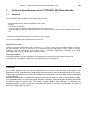
1 . Technical Specifications of the TITRONIC® 500 Piston Burette .......................... 59
1.1
1.2
1.3
Summary ................................................................................................................................. 59
®
Specifications Piston burette TITRONIC 500 ........................................................................ 60
Warning and safety information .............................................................................................. 62
2 . Unpacking and First Operation .............................................................................. 63
2.1
2.2
2.3
2.4
2.4.1
2.4.2
2.4.3
2.4.4
2.4.5
2.5
2.6
2.6.1
2.7
2.7.1
2.7.2
2.7.3
2.8
2.9
Unpacking and First Operation of the Piston Burette.............................................................. 63
Installing the Z 300 Rod Foot Plate (Optional) ........................................................................ 63
Installation and Connection of the TM 235 Magnetic Stirrer ................................................... 64
Connecting the Piston Burette - Combination with Accessories and Additional Devices ....... 65
®
Back panel of the TITRONIC 500 piston burette................................................................... 65
®
Connection ports of the TITRONIC 500 piston burette ......................................................... 65
Connecting a printer ................................................................................................................ 65
Connecting a USB device (manual controller, keyboard, memory device, hub) .................... 65
Connection of analytical balances........................................................................................... 65
Setting the Language of the Country ...................................................................................... 66
Interchangeable unit WA......................................................................................................... 67
Installing the interchangeable unit........................................................................................... 67
Positioning and Replacing an Interchangeable Unit ............................................................... 68
Placing an interchangeable unit .............................................................................................. 68
Removing an interchangeable unit.......................................................................................... 69
Programming the titration unit ................................................................................................. 69
Initial Filling or Rinsing of the Entire Interchangeable Unit ..................................................... 71
Replacing the Glass Cylinder and the PTFE Piston ............................................................... 73
3 . Working with the TITRONIC® 500 ........................................................................... 75
3.1
3.2
3.3
3.4
3.5
3.6
3.6.1
3.6.2
3.6.3
Front Keyboard........................................................................................................................ 75
Display..................................................................................................................................... 75
Manual controller “mouse“ ...................................................................................................... 76
External PC Keyboard............................................................................................................. 76
Menu Structure........................................................................................................................ 77
Main Menu............................................................................................................................... 79
Manual Titration....................................................................................................................... 79
Dosage .................................................................................................................................... 81
Preparing Solutions ................................................................................................................. 83
4 . Method Parameters ................................................................................................. 85
4.1
4.2
4.3
4.4
4.5
4.5.1
4.5.2
4.5.3
4.5.4
4.5.5
Method editing and new method ............................................................................................. 85
Standard Methods ................................................................................................................... 85
Copy Methods ......................................................................................................................... 86
Delete Methods ....................................................................................................................... 86
Change Method Parameters ................................................................................................... 87
Method type............................................................................................................................. 87
Result ...................................................................................................................................... 87
Dosing parameters .................................................................................................................. 92
Sample description.................................................................................................................. 93
Documentation ........................................................................................................................ 94
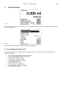
5 . System Settings....................................................................................................... 95
5.1
5.2
5.3
5.4
5.5
5.6
Interchangeable Reagents Unit............................................................................................... 95
RS232 Settings ....................................................................................................................... 97
Date and Time......................................................................................................................... 99
Password................................................................................................................................. 99
RESET .................................................................................................................................... 99
Device Information ................................................................................................................ 100
5.7
5.8
System Sounds ..................................................................................................................... 100
Software Update.................................................................................................................... 101
6 . Data Communication via RS-232- and USB-B interface ..................................... 103
6.1
6.2
6.3
General Information............................................................................................................... 103
Chaining multiple devices — „Daisy Chain Concept“ ........................................................... 103
Instruction Set for RS-Communication.................................................................................. 104
7 . Connection of Analytical Balances and Printers ................................................ 105
7.1
7.1.1
7.2
Connection of Analytical Balances........................................................................................ 105
Balance TZ-Number .............................................................................................................. 105
Connection of Printers........................................................................................................... 106
8 . Maintenance and Care of the TITRONIC® 500 Piston Burette ............................ 107
9 . Storage and transportation................................................................................... 108
10Recycling and Disposal......................................................................................... 108
11Index ....................................................................................................................... 109
last page of the document
Version 110901 US
Declaration of conformity
®
Chapter 1 - Specifications Piston burette TITRONIC 500
1
Technical Specifications of the TITRONIC® 500 Piston Burette
1.1
Summary
59
®
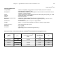
The TITRONIC 500 is suitable for the following applications:
−
−
−
−
−
Manual titration with or without calculation of the result
Dosage
Preparation of solutions
®
It can be used as a dosing burette with the TitroLine 7000 Titrator
It can be used as a dosing or titrating burette in combination with the TitriSoft control software from version
3.0.
A variety of dosing and filling speeds can be set for each method.
Up to 15 user methods can be memorised in the device.
Solutions to be used:
Virtually, any liquids and solutions with a viscosity of < = 10 mm² / s such as concentrated sulphuric acid may
be used. However, one has to avoid the use of chemicals that may attack glass, PTFE or FEP or that are
explosive, such as hydrofluoric acid, sodium azide or bromine! Suspensions containing high solids
percentages may clog or even damage the dosing system.
General provisions:
The safety guidelines that are applicable to the handling of chemicals have to be observed under all
circumstances. This applies in particular to inflammable and/or etching liquids.
Guarantee
We provide guarantee for the device described for two years from the date of purchase. This
guarantee covers manufacturing faults being discovered within the mentioned period of two years.
Claim under guarantee covers only the restoration of functionality, not any further claim for damages
or financial loss.
Improper handling/use or illegitimate opening of the device results in loss of the guarantee rights.
The guarantee does not cover wear parts, as lobes, cylinders, valves and pipes including the thread
connections and the titration tips. The breach of glass parts is also excluded. To ascertain the
guarantee liability, please return the instrument and proof of purchase together with the date of
purchase freight paid or prepaid.
60
®
Chapter 1 - Specifications Piston burette TITRONIC 500
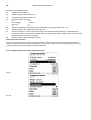
1.2 Specifications Piston burette TITRONIC® 500
th
CE sign:
Country of origin:
Status Aug.9 2011
EMC compatibility according to the Council Directive: 2004/108/EG;
applied harmonized standards: EN 61326-1:2006
Low-voltage directive according to the Council Directive 2006/95/EG
Testing basis EN 61 010, Part 1
Germany, Made in Germany
The following dissolvents/titration reagents are allowed to be used:
− All common titration solutions.
− As reagent water and all non-aggressive non-organic and organic fluids are allowed. If using combustible
fluids fire please adhere to the Guidelines for Explosion Protection and Prevention of the chemical industry.
2
− For fluids with higher viscosity (≥ 5 mm /s), lower boiling point or affinity to outgas, the filling and dosage
speed can be adjusted.
2
− Fluids with viscosity over 20mm /s cannot be dosed.
Display:
3.5 inches -1/4 VGA TFT display with 320x240 pixels.
Power supply:
power supply 90-240 V; 50/60 Hz, power input: 30 VA
RS-232-C Interface:
USB Interface:
RS-232-C interface separated galvanically through photocoupler
Daisy Chain function available.
adjustable, 7 or 8 Bit (default: 8 Bit)
adjustable, 1 or 2 Bit (default: 1 Bit)
static 1 Bit
adjustable: even / odd / none
adjustable: 1200, 2400, 4800, 9600, 19200 (Default 4800 baud)
adjustable, (0 to 15, default: 01)
for computer, input Daisy Chain
devices of SI Analytics, titrator TitroLine 7000,
- Burettes TITRONIC 500, TITRONIC 110 plus, TITRONIC universal,
- Balances of the types Mettler, Sartorius,
Kern, Ohaus (for more, please contact SI Analytics)
- Exit Daisy Chain
2 x USB-type A and 1 x USB-type B
USB –Typ B („slave“)
for connecting a PC
USB –Typ A („master“)
for connecting:
- USB keyboard
- USB printer
- USB „mouse“ („mouse“),
- USB data media e.g. USB stick
- USB Hub
12V DC out, 500mA
power supply for stirrer TM 235, TM 135
Data bits:
Stop bit:
Start bit:
Parity:
Baud rate:
Address:
RS-232-1
RS-232-2
Stirrer connection:
Housing material:
Front keyboard:
Housing dimensions:
Weight:
Ambient conditions:
Polypropylene
polyester coated
15.3 x 45 x 29.6 cm (W x H x D), height incl. interchangeable unit
ca. 2.3 kg for basic unit
ca. 3.5 kg for complete device incl. interchangeable unit (with empty reagent bottle)
Ambient temperature: + 10 ... + 40 °C for operation and storage
Humidity according to EN 61 010, Part 1:
Max. relative humidity 80 % for temperatures up to 31 °C,
linear decrease down to 50 % relative humidity at a temperature of 40 °C
®
Chapter 1 - Specifications Piston burette TITRONIC 500
61
th
Status Aug.9 2011
Interchangeable units
®
Compatibility:
®
units are compatible to the titrators TitroLine 6000, TitroLine 7000 and
®
Piston Burette TITRONIC 500
automatically through RFID. Recognition of unit size and characteristics of the
Titration- or dosing solution
volume neutral cone valve made from fluorocarbon polymers (PTFE), TZ 3000
®
borosilicate glass 3.3 (DURAN )
FEP hose set, blue
suitable for square glass bottle and misc. reagent bottles
®
borosilicate glass DURAN , fluorocarbon polymers (PTFE), stainless steel,
polypropylene,
15 x 34 x 22.8 cm (W x H x D) incl. reagent bottle
approx. 1.2 kg for interchangeable unit WA incl. empty reagent bottle
Recognition:
Valve:
Cylinder:
Hoses:
Bracket for supply bottle:
Materials:
Dimensions:
Weight:
Dosing accuracy:
Accuracy:
Precision:
after DIN EN ISO 8655, part 3
0.1 – 0.15 %
0.05 - 0.07 %
(depending on the used interchangeable unit)
®
Dosing accuracy of the Piston Burette TITRONIC 500 with WA interchangeable units:
Interchangeable.
unit
type No.
Volume
[ml]
Tolerances of the Øi
of the glass cylinder
[mm]
Dosage error*
according to
100 % volume
[%]
Reproducibility
[%]
WA 05
5.00
± 0.005
± 0.15
0.07
WA 10
10.00
± 0.005
± 0.15
0.05
WA 20
20.00
± 0.005
± 0.15
0.05
WA 50
50.00
± 0.005
± 0.15
0.05
®
Chapter 1 - Specifications Piston burette TITRONIC 500
62
1.3 Warning and safety information
The Piston Burette TITRONIC 500 corresponds to protection class II. It was manufactured and tested
according to DIN EN 61 010, Part 1, Protective Measures for Electronic Measurement Devices and has left the
factory in an impeccable condition as concerns safety technology. In order to maintain this condition and to
ensure safe operation, the user should observe the notes and warning information contained in the present
operating instructions. Development and production is done within a system which meets the requirements laid
down in the DIN EN ISO 9001 standard.
For reasons of safety, the Piston Burette TITRONIC 500 must be opened by authorised persons only; this
means, for instance, that work on electrical equipment must only be performed by qualified specialists.
In the case of nonobservance of these provisions the Piston Burette TITRONIC 500 may constitute
a danger: electrical accidents of persons or fire hazard. Moreover, in the case of unauthorised
intervention in the Piston Burette TITRONIC 500 as well as in the case of negligently or deliberately
caused damage, the warranty will become void. !
!
Prior to switching the device on it has to be ensured that the operating voltage of the Piston Burette
TITRONIC 500 matches the mains voltage. The operating voltage is indicated on the specification plate.
Nonobservance of this provision may result in damage to the Piston Burette TITRONIC 500 or in personal
injury or damage to property.
If it has to be assumed that safe operation is impossible, the Piston Burette TITRONIC 500 has to be put out
of operation and secured against inadvertent putting to operation. In this case please switch the Piston Burette
TITRONIC 500 off, pull plug of the mains cable out of the mains socket, and remove the Piston Burette
TITRONIC 500 from the place of work.
Examples for the assumption that a safe operation is no longer possible,
the package is damaged,
the Piston Burette TITRONIC 500 shows visible damages,
the Piston Burette TITRONIC 500 does not function properly,
liquid has penetrated into the casing.
The Piston Burette TITRONIC 500 must not be stored or operated in humid rooms.
For reasons of safety, the Piston Burette TITRONIC 500 must only be used for the range of application
described in the present operating instructions.
In the case of deviations from the intended proper use of the device, it is up to the user to evaluate the
occurring risks.
The relevant regulations regarding the handling of the substances used have to be observed: The
Decree on Hazardous Matters, the Chemicals Act, and the rules and information of the chemicals trade. It
has to be ensured on the side of the user that the persons entrusted with the use of the Piston Burette
TITRONIC 500 are experts in the handling of substances used in the environment and in the Piston Burette
TITRONIC 500 or that they are supervised by specialised persons, respectively.
!
During all work with titration solutions: ! Please wear protective glasses! !
®
The TITRONIC 500 Piston Burette is equipped with integrated circuits (EPROMs). X rays or other high energy
radiation may penetrate through the device’s casing and delete the program.
For working with liquids, not beeing common titration solvents, especially the chemical resistance of the
®
construction materials of the TITRONIC 500 have to be considered (please also refer to chapter 1.1).
For the use of liquids with high vapor pressure or (mixture of) substances not being mentioned in chapter 1.1
®
as allowed substances, the safe and proper operation of the Piston Burette TITRONIC 500 has to be
guaranteed by the user.
When the piston moves upwards within the cylinder, a microfilm of dosing liquid or titration solution will always
remain adhered to the inner wall of the cylinder, but this has no influence on the dosing accuracy. This small
residue of liquid, however, may evaporate and thus penetrate into the zone underneath the piston, and if nonadmitted liquids are being used, the materials of the TITRONIC universal Piston Burette may be dissolved or
®
corroded (please refer also to chapter 8 "Maintenance and Care of the Piston Burette TITRONIC 500").
Chapter 2 - Unpacking and first Operation
2
63
Unpacking and First Operation
2.1 Unpacking and First Operation of the Piston Burette
The piston burette itself as well as all related accessory and peripheral parts have been carefully checked at the
factory to ensure their correct function and size.
Please ensure that the small accessories are also removed in full from the packaging.
For the scope of delivery, please refer to the enclosed parts list.
®
The TITRONIC 500 piston burette may be placed on any flat surface.
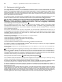
2.2 Installing the Z 300 Rod Foot Plate (Optional)
If the TM 235 magnetic stirrer is not in use, it is recommended to use the Z 300 rod foot plate. The Z 300 rod foot
plate is made of solid metal (fig. 1). The bottom of the device contains a recess which is precisely worked to
accommodate the metal foot plate. The metal foot plate itself features one thread on both sides (top and bottom)
to hold the stand rod (coming with the basic device). This means that the metal foot plate can be used both to the
left and to the right of the device, depending on the specific needs. The basic device is to be placed on the metal
foot plate; subsequently the stand rod is screwed into the thread. Now it is possible to install the Z 305 titration
clamp (included with the basic device) on the stand rod (fig. 2).
Fig. 1
Fig. 2
64
Chapter 2 - Unpacking and first Operation
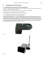
2.3 Installation and Connection of the TM 235 Magnetic Stirrer
As a rule, the TM 235 magnetic stirrer is arranged to the right of the piston burette. The magnetic stirrer is
connected to the 12V out-socket in the rear panel of the piston burette using the TZ 1577 connection cable
(scope of delivery of the basic device) (cp. ‘Back panel’ illustration, chapter 2.4). The stand rod (scope of delivery
of the basic device) is screwed into the thread; subsequently the Z 305 titration clamp (scope of delivery of the
basic device) is installed (fig. 3).
Fig. 3
Chapter 2 - Unpacking and first Operation
65
2.4 Connecting the Piston Burette - Combination with Accessories and Additional
Devices
2.4.1
®
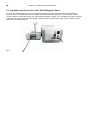
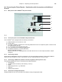
Back panel of the TITRONIC 500 piston burette
1
2
3
4
5
6
Fig. 4
2.4.2
®
Connection ports of the TITRONIC 500 piston burette
®
The TITRONIC 500 is equipped with the following connections:
1) USB-B interface for connection to a PC
2) On/Off switch
3) Two USB-A („Master“) interfaces for connecting USB devices such as a keyboard, printer, manual control
unit, USB memory stick etc
4) “in“: Connection of the external power pack
5) “out“: Connection of the TM 235 magnetic stirrer
6) Two RS232 interfaces, 4-channel (Mini-DIN):
RS1 for connection to the PC
RS2 for connection of a weighing balance and other devices from von SI Analytics (burettes, sample
changers)
2.4.3
Connecting a printer
Printers with a USB interface are to be connected to one of the two USB-A interfaces. These printers have to
feature HP PCL emulation (3, 3GUI, 3 enhanced, 5, 5e). So-called GDI printers cannot be used!
2.4.4
Connecting a USB device (manual controller, keyboard, memory device, hub)
The following USB devices can be connected to the USB-A interfaces:
• PC-keyboard
• TZ 3880 manual controller (in the following: ”mouse“)
• Printer
• USB storage devices, e.g. USB sticks
• USB hub
• USB barcode scanners
2.4.5
Connection of analytical balances
Analytical balances are to be connected to the RS232-2 using an appropriate cable.
66
Chapter 2 - Unpacking and first Operation
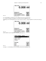
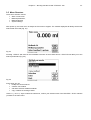
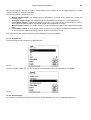
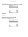
2.5 Setting the Language of the Country
The ex-factory default language setting is English. When the piston burette is switched on, the main menu will
appear once the boot sequence is completed:
Fig. 5
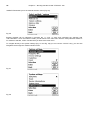
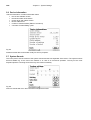
Using <SYS/<F7> or <MODE>, followed by <System settings> you navigate to the system settings. The very first
menu is to be used for setting the language of the country:
:
Fig. 6
Use <ENTER>/<OK> to call the menu. Select the national language using the <↑↓> arrow keys, confirm it with
<ENTER>/<OK>:
Fig. 7
The selected language will appear immediately. Pressing the <ESC> key twice will return the user to the main
menu.
Chapter 2 - Unpacking and first Operation
67
2.6 Interchangeable unit WA
1
6
2
7
3
8
10
9
4
11
5
Fig. 8
1) TZ 3871 - suction hose
2) TZ 3872 - connection hose
3) TZ 3873 - dosing hose without dosing tip and holding bracket;
TZ 3874 - dosing hose with dosing tip and holding bracket
4) TZ 3801 - valve cover lid
5) TZ 3000 - 3/2-way valve
6) TZ 2003 - drying tube
7) TZ 3802 - threaded cap with borehole GL 45, incl. adapter with 2 openings for drying tube and suction
hose
8) TZ 3803 - 1 litre reagent bottle, brown
9) TZ 3900 - UV protection, blue transparent
10) TZ 3875 - shaft for titration tip and
TZ 3656 - titration tip unit, blue
11) TZ 1507 - plastic drip-down tubule
2.6.1
Installing the interchangeable unit
Fig. 8 shows a completely assembled interchangeable unit.
•
Remove the valve with the attached hoses from the pack, then push it on the valve support until it snaps
in position.
• Slip on the valve cover lid on the valve as is shown in the illustration.
• Insert the TZ 3872 connection hose in the threaded hole provided in the burette cylinder, then tighten it
by hand.
• Insert the TZ 3871 suction hose into the threaded opening of the GL 45 or S 40 adapters, then tighten it
manually.
All the other hoses are already preassembled.
Chapter 2 - Unpacking and first Operation
68
2.7 Positioning and Replacing an Interchangeable Unit
The base unit comes with an RFID reader, and all the interchangeable units are equipped with an RFID
transponder. This transponder can be used to store the following information:
•
•
•
•
•
•
•
•
•
•
Unit size (cannot be changed)
Unit ID (cannot be changed)
Reagent name (default: blank)
Concentration (default: 1.000000)
Concentration determined on: (Date)
To be used until: (Date)
Opened/Produced on: (Date)
Test according to ISO 8655: (Date)
Charge description: (default: no charge)
Last modification: (Date)
Each time an interchangeable unit is pushed onto the base unit, the data is automatically read out of the
transponder.
2.7.1
Placing an interchangeable unit
The interchangeable unit is to be placed on the device unit as is shown in fig. 9 a-c; subsequently, it is to be
pushed downwards until the black button latches on the left side.
Fig. 9.a
Fig. 9.b
Chapter 2 - Unpacking and first Operation
69
Fig. 9.c
2.7.2
Removing an interchangeable unit
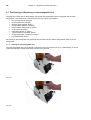
Removing the interchangeable unit is done in reverse order:
•
Depress the black button on the left, and then pull the interchangeable unit forward as is shown in fig. 9.c
– 9.a.
! Please note: Removing the interchangeable unit is only possible as long as the piston is in the lower
position (zero position). Possibly, it may be necessary to press the <FILL> key first. !
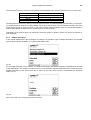
2.7.3
Programming the titration unit
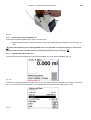
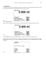
The data from the RFID transponder of the interchangeable unit will be read immediately (fig. 10).
Fig. 10
Following the reading operation, the input menu for the input of the reagents will be shown for approx 10 seconds
(fig. 11). The size of the interchangeable unit is displayed on the left side of the display (here 10 ml).
Fig. 11
70
Chapter 2 - Unpacking and first Operation
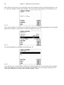
When used for the first time, it is recommended to enter here at least the name of the reagent being used. To do
so, confirm the “Reagent“ selection with <ENTER>, then type the name and possibly the concentration (fig. 12).
Fig. 12
Press <OK>/<ENTER> to confirm (fig. 12). Following the optional input of additional parameters (for more details
please refer to chapter 5.1), press <ESC> to leave the reagents menu (fig. 13).
Fig. 13
You will be prompted for a confirmation of the values (fig. 14):
Fig. 14
If you selected <Yes>, the values will be written into the interchangeable unit. You can see this from a message
in red colour displayed at the bottom. Upon completion, the left bottom corner of the display will show the new
name of the reagent (fig. 15). In the present case this is NaOH 0.1 mol/L.
Chapter 2 - Unpacking and first Operation
71
Fig. 15
2.8 Initial Filling or Rinsing of the Entire Interchangeable Unit
Initial filling of the interchangeable unit is done using the <rinsing > rinsing programme. On the main menu (fig.
16),
Fig. 16
press <MODE> key to navigate to the methods/system (fig. 17).
Fig. 17
Pressing <↑> once will take you to the <Rinsing> selection immediately (fig. 18).
72
Chapter 2 - Unpacking and first Operation
Fig. 18
Confirm the selection by pressing <ENTER>:
Fig. 19
At this point you can select the number of rinsing cycles (Fig. 19). Initial filling requires a minimum of two rinsing
cycles. You can stop the rinsing operation (Fig. 20) at any time by pressing <STOP> and then resume rinsing
with <START>.
Fig. 20
While the initial filling or rinsing programme is being run, please place a sufficiently dimensioned waste vessel
under the titration tip.
Chapter 2 - Unpacking and first Operation
73
2.9 Replacing the Glass Cylinder and the PTFE Piston
Replacing the glass cylinder and the piston does not require any additional tools. In certain cases the piston
extractor has to be used.
•
•
•
•
•
•
•
Remove the interchangeable unit from the base unit.
Unscrew the hose between the glass cylinder and the valve from the glass cylinder.
Rotate the blue UV protection 5 to 6 times to the left to loosen it.
You can remove the UV protection and pull out of the glass cylinder together with the piston inside it.
Insert a new glass cylinder and piston (Fig. 21) into the interchangeable unit, and then slip on the blue
UV protection again.
Tighten the blue UV protection again by rotating it 5 to 6 times to the right.
The piston rod should project 1-2 cm out of the interchangeable unit (Fig. 22 a). At this point, tilt the unit
forward until the slanted bottom side is in flat contact with the lab table (Fig. 22 b). This forces the piston
into its correct position. Should the piston be forced somewhat too far into the glass cylinder, simply pull it
out and place it in the correct position according to the procedure described above.
Glass cylinder
Piston rod
Fig. 21
Piston rod
Fig. 22 a
74
Chapter 2 - Unpacking and first Operation
Fig. 22 b
Basically, it should be noted that within one and the same interchangeable unit only the specified cylinder size
may be installed, since otherwise the coding which is memorised within the interchangeable unit will no longer
match the cylinder size. This will entail incorrect dosage. And for the sake of dosing and analytical accuracy, it is
also recommended to replace the PTFE pistons each time a defective glass cylinder is replaced. This applies in
particular to glass breakage, since broken glass may damage the sealing rings of the PTFE piston.
Please note: As a rule, the hoses and cylinders will contain chemicals which may spill or be splashed around in
the course of disassembly. The relevant safety precaution measures applicable to the handling of the chemicals
concerned have to be observed.
®
Chapter 3 – Working with the burette TITRONIC 500
3
75
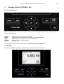
Working with the TITRONIC® 500
3.1 Front Keyboard
Apart from alphanumeric input (a-z, A-Z, 0-9) and a few other functions, almost all functions can be performed
using the front keyboard.
<Mode>:
<EDIT>:
<ESC>:
<START>:
<FILL>:
Methods selection, rinsing, system settings
Changing the current method, new method, copy and delete method
<ESC> will take you back to the previous menu level.
Start and Stop of a current method
Filling the unit
The individual functions are described in detail in Chapter 3.4, External PC Keyboard.
3.2 Display
The display consists of a graphical LCD display with a resolution of 320 x 240 pixels.
®
Chapter 3 – Working with the burette TITRONIC 500
76
3.3 Manual controller “mouse“
The “mouse“ (Fig. 23) is needed for manual titration. It can also be used for starting dosage or other methods.
Fig. 23
Mode
Manual titration
Dosage through Dosage method
Preparation of solutions
Black key
Start of titration, single-step and
continuous titration (please refer to
chapter 3.6.1, manual titration)
Start dosage
Start dosage
Gray Key
Filling
Stop of titration including evaluation
Filling
Filling
3.4 External PC Keyboard
Keys
<ESC>
<F1>/<START>
<F2>/<STOP>
<F3>/<EDIT>
<F4>/<FILL>
<F5>/
<F6>/<MODE>
<F7>/<SYS>
<F8/<CAL>
<F9>/+ / <F10>/<DOS>
Num/ Scroll
Lock/ Lock
Prt Sc
Sys Rq
<ESC>
< ↑> < ↓ > <←> <→>
0...9
<ENTER>
< ←Backspace >
Letters,
ASCII-symbols
All other keys
Function
<ESC> will take the user to the previous level on the
menu.
Start of a selected method
Stop of the current method
Change of the current method, new method, copy method
Fill the interchangeable unit
Display and modification of the balance data
Selection of method, rinsing, system settings
System settings (language selection, time/date ...)
®
No function on the TITRONIC 500
Change of sign
Call dosing menu
Without function
Without function
Selection of the method-selection menu from the main
menu.
Elders: <ESC> will take you back to the previous level in
the menu.
Selection of individual menus and numeric values
Input of numeric values
Confirmation of input parameters
Deletion of one input digit / an input character to the left of
the blinking cursor
Alphanumeric input possible. Uppercase and lowercase
possible.
Do not have any function
®
Chapter 3 – Working with the burette TITRONIC 500
77
3.5 Menu Structure
There are 4 selection menus:
• Start or main menu
• Method parameters,
• Method selection
• System settings
After power-up, the main menu is always the first menu to appear. The method displayed will always be the last
method that was used (Fig. 24).
Fig. 24
Pressing <START> will result in the immediate execution of the method shown. <EDIT>/F3 will take you to the
method parameters (Fig. 25).
Fig. 25
At this point you can
• modify the current method
• create a new method
• call and memorise standard methods
• copy or delete an existing method
Use the <↓> und <↑> keys to select the submenus, confirm your selection with <OK>/<ENTER>. <ESC> will take
you back to the main menu.
78
®
Chapter 3 – Working with the burette TITRONIC 500
<MODE>/F6 will take you to the method selection menu (Fig. 26).
Fig. 26
Existing methods can be selected by pressing the <↓> und <↑> keys and confirming the selection with
<OK>/<ENTER>. Once the selection made, you will return to the main menu with the newly selected method. If
no method is selected, <ESC> will also take you back to the main menu.
To navigate directly to the system settings (Fig. 27 and Fig. 28) you can use the <SYS>/F7 key; you can also
navigate there through the method selection menu.
Fig. 27
Fig. 28
®
Chapter 3 – Working with the burette TITRONIC 500
79
3.6 Main Menu
After power-up, the main menu is always the first menu to appear. The method displayed will always be the last
method that was used (Fig. 29). In the present case it was a titration method.
Fig. 29
3.6.1
Manual Titration
Manual titration is always performed using the "mouse". Manual titration is impossible without the „mouse“.
Fig. 30
Using <START>/<F1> or pressing the Black key on the “mouse“ will start the manual titration method.
Depending on the settings of the method, the system will prompt you for the sample description (Fig. 31) and the
sample weight (Fig. 32). You can use an external PC keyboard to enter a 20-digit alphanumeric sample
description.
Fig. 31
80
®
Chapter 3 – Working with the burette TITRONIC 500
Fig. 32
The balance data can be input using the front keyboard or the external keyboard. Please confirm your selection
using <OK>/<ENTER>.
In the case of automatic takeover of the weighing-balance data, the sample weights will be read out of the
balance data memory. If the memory does not contain any balance data, a message informing you of the
absence of balance data will be displayed (Fig. 33).
Fig. 33
Even at this moment, pressing the Print key on the balance will still cause the transfer of the balance data. After
the input of the sample description and/or the sample weight/ sample volume, the following display will appear:
Fig. 34
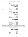
You can control the metering rate with the black key of the “mouse“. A single depression of the key will cause a
step up to the first level. Depending on the size of the interchangeable unit, this corresponds to 0.0005 ml (WA
05), 0.001 ml (WA 10), 0.002 ml (WA 20) and 0.005 ml (WA 50).
If one keeps the black key depressed on the first level, titration will be continued at a low rate. If you press the
nd
black key fully down (2 level) titration will proceed at a higher rate. The rate of the second level can be set in
five stages using the <↓↑> arrow keys. These stages can also be changed during manual titration.
®
Chapter 3 – Working with the burette TITRONIC 500
81
Fig. 35
Stage 5 corresponds to maximum titration speed. Speed is reduced by 50% each time.
Example: WA 20 interchangeable unit:
Stage 5
Stage 4
Stage 3
Stage 2
Stage 1
40.00 ml/min
20.00 ml/min
10.00 ml/min
5 ml/min
2.5 ml/min
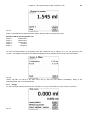
As soon as manual titration is completed, press the <STOP/F2> key or approx. for 1 sec. the grey key of the
“mouse”. The titration result will be calculated and displayed and optionally printed on the connected printer:
Fig. 36
<ESC> will take you back to the start menu way to start the next titration immediately. Filling of the
interchangeable unit occurs automatically.
3.6.2
Dosage
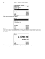
To start a dosage method, please use the <START>/<F1> key or the black key of the „mouse“ ("mouse").
Fig. 37
82
®
Chapter 3 – Working with the burette TITRONIC 500
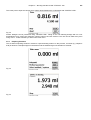
Fig. 38
The dosed volume will be briefly displayed before the display returns to the main menu.
Fig. 39
2
2
Fig. 40
The next dosage operation can be started immediately. Filling of the unit following dosage will not occur
automatically, unless the maximum cylinder volume has been reached or the automatic filling option was
activated. The unit can be filled at any time using <FILL>.
A dosing operation can also be performed without any dosing method with the <DOS>/<F10> key of the external
keyboard:
Fig. 41
®
Chapter 3 – Working with the burette TITRONIC 500
83
This is the point to input the volume which will be dosed following the confirmation with <ENTER>/<OK>:
Fig. 42
Further dosages can be performed using <ENTER>/<OK>. Filling of the unit following dosage will not occur
automatically here, unless the maximum cylinder volume has been reached. The unit can be filled at any time
using <FILL>. <ESC> will take you back to the main menu.
3.6.3
Preparing Solutions
The so-called “Preparing solutions“ method is a special dosing method. In this process, a solvent (e.g. sulphuric
acid) is dosed to a sample weight of a substance until the desired target concentration is reached:
Fig. 43
Fig. 44
84
®
Chapter 3 – Working with the burette TITRONIC 500
Fig. 45
If the calculated volume is greater than the maximum volume, an error message will be displayed and dosage will
be suppressed for safety reasons:
Fig. 46
Chapter 4 Method Parameters
4
85
Method Parameters
From the main menu shown in (Fig. 43/Fig. 24), <EDIT>/<F3> will take you to the method parameters:
Fig. 47
4.1 Method editing and new method
If you select <edit method> or <new method> you will be taken to the modification or new creation of a method.
Selecting <new method> will always lead to the prompt for the input of a method name (Fig. 48). This prompt will
not appear in the case of the modification of an already created method.
Fig. 48
The method name can contain up to 21 characters. Special characters are also possible. If no keyboard is
connected, the method name being displayed has to be adopted (in the present case „Method 04“). Numbering of
methods will occur automatically. Press <OK>/<ENTER> to confirm the input. The method name can be changed
at any time. Please continue at this point with Chapter 4.5.
4.2 Standard Methods
®
The <Standard methods> item of the TITRONIC 500 contains a series of ready-made standard methods which
can be conveniently selected (Fig. 49).
Fig. 49
86
Chapter 4 Method Parameters
Once the selection made, you are directly prompted for the input of the method name (Fig. 50).
Fig. 50
The standard name may be adopted or modified. Subsequently, you will be taken to the <Change method
parameters> item. Please continue at this point with Chapter 4.5.
4.3 Copy Methods
Methods can be copied or stored with a new name. If you select this function, the current method will be copied
and you can include a new name (Fig. 51)
Fig. 51
A new name with the suffix [1] will be assigned automatically, so as to avoid the existence of 2 methods having
the same name. Subsequently, you will be taken to <Change method parameters>. Please continue at this point
with Chapter 4.5.
4.4 Delete Methods
If this function is selected, you will be prompted to know whether the current method is actually to be deleted.
You have to reply <Yes> in explicit terms and also confirm this reply with <OK>/<ENTER>.
Fig. 52
Chapter 4 Method Parameters
87
4.5 Change Method Parameters
The input or modification of the method name was already described in Chapters 4.1 and 4.3.
Fig. 53
4.5.1
Method type
On the <Method type> you can select whether you wish to perform a manual titration or a dosage or whether you
wish to prepare a solution (Fig. 54).
Fig. 54
The selection of the Method type will have an influence of the further parameterisation of the method. For
instance, if you select the dosing mode, no selection of a formula will be available.
4.5.2
Result
The <Result> menu offers the following possible settings:
Fig. 55
The Result text may contain up to 21 alphanumeric characters including special characters.
Chapter 4 Method Parameters
88
Fig. 56
Please confirm your input with <OK</<ENTER>.
4.5.2.1 Formulae for manual titration
On the Formula Selection submenu you can select the appropriate calculation formula:
Fig. 57
The following calculation formulae are available for manual titration:
Titration formula
(EP1-B)*T*M*F1/(W*F2)
(B-EP1)*T*M*F1/(W*F2)
(B*F3–EP1*F1)*T*M/(W*F2)
(W*F2)/(EP1-B)*M*F1)
EP1
Additional information
Formula for calculating the concentration of a
sample taking into account a blank value in
terms of ml.
Formula for calculating the concentration of a
sample taking into account a blank value in
terms of ml. Reverse titration (examples. CSB,
saponification number)
Formula for calculating the concentration of a
sample taking into account a blank value,
including a multiplicative factor. Reverse
titration.
Formula for calculating a titer (T) of a titration
solution.
Used to calculate the consumption in ml
Legend of the abbreviations used:
EP:
B:
T:
M:
F1
F2
W
Titration solution consumption in ml
Blank value in ml, in most cases determined by titration
Titer of the titration solution (e.g. 0.09986)
Mol; Mol- or equivalent weight of the sample (e.g. NaCl 58.44)
Factor 1, Conversion factor
Factor 2, Conversion factor
Weight, sample weight in grams or sample volume in ml.
Chapter 4 Method Parameters
89
After selecting a formula, please confirm your selection with <OK>/<ENTER>:
Fig. 58
The values of the individual parameters of the selected calculation formula can now be input one by one.
Fig. 59
4.5.2.2 Formulae for the Preparation of Solutions
A selection of special calculation formulae is available for the Prepare Solutions mode. The appropriate
calculation formula is selected on the Formula Selection submenu:
Fig. 60
A selection of 3 different calculation formulae is available:
W*(100-Fa-Fb)*Fc/Fd - W*(100-Fb) / (100*Fe) +Ff
W*(100-Fa-Fb)*(Fd/Fg ) - W*(100-Fb) / (100*Fg) +Ff
W*(100-Fa-Fb)*Fc / (100*Fd)
Chapter 4 Method Parameters
90
Meaning of the individual factors:
W:
Fa:
Fb:
Fc:
Fd:
Fe:
Ff:
Fg:
Weight of the sample in g
Soluble foreign-matters portion in %
insoluble foreign-matter portion in %
Conversion factor for it unit
g/l
= 10
mg/l und ppm
= 10000
g/100 ml
=1
%
=1
Target concentration of the solution to be prepared in g/l, mg/l (ppm), g/100 ml, or %
Specific weight of the weighted-in sample in g/cm³
Volume correction in ml. this volume correction is the required surplus dosage for compensating the
volume contraction and the specific-weight difference between the sample weight and the solvent (please
observe the note on volume correction)
Specific weight of the solvent used in g/cm³
Note on volume correction:
The user has to decide on a case-by-case basis whether a volume correction is necessary and according to
which procedure this correction is to be performed. As a rule, this volume correction may be omitted in the case
of solutions with very low percentages of diluted substance.
4.5.2.3 Sample weight and volume (sample quantity)
Fig. 61
Fig. 62
Chapter 4 Method Parameters
91
The Sample Quantity (W) item is used to select whether one is wishing to use a sample weight or a sample
volume for titration or solution preparation.
You have the following options (Fig. 62):
•
•
•
•
•
Manual sample weight: The sample weight is enquired by a prompt at the start of the method and
manually input.
Automatic sample weight: The sample weight is automatically transferred by a connected balance.
Fixed sample weight: A fixed sample weight is input in g. This weight will then automatically be used for
each start of the method without any sample weight being enquired by a prompt.
Manual sample volume: The sample volume in ml is prompted at the start of the method and manually
input.
Fixed sample volume: A fixed sample volume is input in ml. this volume will then automatically be used
for each test of the method without any sample volume enquired by a prompt.
Note: Manual and firm sample volumes are orally available of for manual titration.
4.5.2.4 Formula unit
The formula unit can be selected in the Unit submenu.
Fig. 63
Once the selection made (e.g. %), the unit will also be displayed as piece of information on the display.
Fig. 64
4.5.2.5 Decimal digits
To conclude, it is possible to determine the number of decimal digits from 2-6. The standard setting is 2.
Chapter 4 Method Parameters
92
4.5.3
Dosing parameters
Fig. 65
The dosing parameters (dosing speed, filling speed and max. dosing/titration volume) are determined for each
method. This applies to all types of methods such as manual titration, dosing and Solution Preparation.
Fig. 66
Chapter 4 Method Parameters
93
The dosing speed can be set as a function of the interchangeable unit in terms of ml/min from 0.1 to 100 ml/min.
Interchangeable unit
WA 05
WA 10
WA 20
WA 50
Max. dosing speed [ml/min]
10
20
40
100
The filling speed can be set in terms of seconds from 20 to 999. The standard setting of this value is 30 seconds.
For diluted aqueous solutions the filling speed can be six to 20 seconds. For non-aqueous solutions the filling
speed should be set to the 30 seconds. In the case of highly viscous solutions such as concentrated sulphuric
acid the filling speed should be further reduced down to 40 - 60 seconds.
Depending on the method type, the (maximum) the living volume or titration volume can be set to 999.999 or
even 9999.999.
4.5.4
Sample description
In the manual titration and in the preparation of solutions it is possible to input a sample description. The possible
input includes manual, automatic or no sample description at all.
Fig. 67
For a sample description of the ’manual’, a prompt for the sample description will always be displayed at the start
of the method (Cp. also chapter 3.6, Main menu). For an ‘automatic’ sample description there will be selected a
master description (in the current case this is water, cp. Fig. 68), which will then automatically be numbered
starting on 01.
Fig. 68
After a new power-up, numbering will resume with 01.
Chapter 4 Method Parameters
94
4.5.5
Documentation
Fig. 69
Two different format settings are available for documentation on a printer: short and GLP:
Fig. 70
Note: The “standard with curve“ format is only applicable to automatic titrators.
Method type
Manual titration
Dosing
Prepare solutions
Short documentation
Method name, date, time, sample
description, sample weight/sample
volume, results and calculation
formula
Method name, date, time
Standard documentation
N/A
GLP-Documentation
Same as ‘Short
documentation’ +
plus method contents
N/A
Method name, date, time, sample
designation, weight/sample, results
and calculation formula
N/A
Same as ‘Short
documentation’ +
method contents
Same as ‘Short
documentation’ +
method contents
Documentation in a PDF file stored on a connected USB stick will soon be available with a new update. Please
contact your dealer or SI Analytics directly.
Chapter 5 - System Settings
5
95
System Settings
Fig. 71
From the main menu (Fig. 71), <SYS>/<F7> or the <MODE> front keys, followed by <System settings> you get
to the system settings:
Fig. 72
Setting the national language was already described in Chapter 2.5.
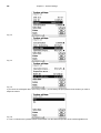
5.1 Interchangeable Reagents Unit
Each interchangeable unit is equipped with an RFID transponder. This transponder can be used to store the
following information:
•
•
•
•
•
•
•
•
•
•
Unit size: (the default setting, cannot be changed)
Unit ID: (default setting, cannot be changed)
Reagent name: (default: blank)
Concentration: (default: 1.000000)
Concentration determined on: (Date)
To be used until: (Date)
Opened/Produced on: (Date)
Test according to ISO 8655: (Date)
Charge description: (default: no charge)
Last modification: (Date)
96
Chapter 5 - System Settings
Fig. 73
Fig. 74
Fig. 75
If you leave the <Reagents WA> menu using <ESC>, you will always be prompted to know whether you wish to
adopt the values:
Fig. 76
If <Yes> is selected, the updated values will be written into the RFID transponder of the interchangeable unit.
Chapter 5 - System Settings
97
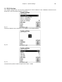
5.2 RS232 Settings
®
The <RS232 settings> item can be used to determine the device address of the TITRONIC 500 and set the
parameters of the two RS232 interfaces separately:
Fig. 77
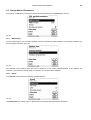
The device address can be set from 0 – 15. Address 1 is the default setting:
Fig. 78
Fig. 79
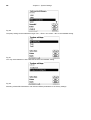
The baud rate is preset to 4800. It may be set to 1200 – 19200:
98
Chapter 5 - System Settings
Fig. 80
The parity setting can be selected amongst <No>, <Even> and <Odd>. <No> is the standard setting.
Fig. 81
You may select between 7 and 8 data bits. 8 bits is the standard setting.
Fig. 82
Selecting <Reset RS Parameters> will reset the RS232 parameters to the factory settings.
Chapter 5 - System Settings
99
5.3 Date and Time
The factory time setting is Central European Time. This setting may be changed, where necessary:
Fig. 83
5.4 Password
The password function is currently not yet activated. Please ask your dealer for an update.
5.5 RESET
RESET will reset all settings to the factory setting.
Please note: All methods will also be deleted. So please print the methods or export/copy them to a connected
USB storage medium (this will be possible with a higher update!).
The RESET has to be confirmed separately once again:
Fig. 84
100
Chapter 5 - System Settings
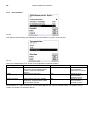
5.6 Device Information
<Device Information> contains information about
• the current software version
• the serial number of the device
• printer driver and update version
• device address set
• number of measurements (Starts of a method)
• a number of strokes/filling cycles
Fig. 85
Please hold this device information ready for service purposes.
5.7 System Sounds
This is the point to set the volume of the system sounds and the front keyboard of the device. The system sounds
become audible e.g. at the end of the titration or in case of an erroneous operation. The keys of the front
keyboard produce a clicking sound if the key was used successfully.
Fig. 86
Note: No sounds will occur when the external keyboard is used.
Chapter 5 - System Settings
101
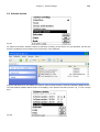
5.8 Software Update
Fig. 87
An update of the device software requires a USB stick containing a new version. For this operation, the two files
that are needed have to be located in the root directory of the USB stick:
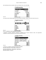
Plug the USB stick into a free USB-A port, wait for some seconds, and then select the Software Update function.
The valid software updates will be shown on the display. In the present case this is Version „16_11“ from 19 April
2011.
Fig. 88
102
Chapter 5 - System Settings
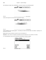
After starting the update using <OK/ENTER>, next thing to appear is the following graphic:
Fig. 89
which will change after a few seconds to the following display:
Fig. 90
Upon completion of the update (approx. 1-2 minutes), the device will shut down the software completely and
proceed to a new start.
Please note: During the update, the device must not be switched off.
Important: In the course of an update, the methods will not be deleted! You can continue to use them.
If no valid update file is stored on the USB stick, the following message will appear:
Fig. 91
Chapter 6 Data Communication via RS-232 and USB-B interface
6
103
Data Communication via RS-232- and USB-B interface
6.1 General Information
®
The burette TITRONIC 500 has two serial RS-232-C interfaces to communicate data with other devices. By
means of these two interfaces it is possible to operate several devices on one computer (PC) interface.
®
In addition to that, the TITRONIC 500 also has an alternatively USB-B interface, which can only be used to
connect a PC.
RS-232-C-1 establishes the connection to a connected computer or to the previous device of the “Daisy
Chain”.At the RS-232-C-2 it is possible to connect additional devices (Daisy Chain Concept).
PIN assignment of the RS-232-C interfaces:
PIN-No.
1
2
3
Meaning / Description
T x D Data output
R x D Data input
Digital mass
6.2 Chaining multiple devices — „Daisy Chain Concept“
In order to activate several devices in a chain individually, each device must have an own device address. For
this it is at first necessary to establish a connection from the computer to the RS-232-C interface 1 of the first
devise in the chain by means of a RS-232-C data cable, e.g. Type No. TZ 3097. With the additional RS-232-C
data cable, Type No. TZ 3094, the RS-232-C- interface 2 of the first device is connected with the RS-232-Cinterface 1 of the second device. At interface 2 of the second device it is possible to connect an additional device.
®
The TITRONIC 500 can also be connected via USB cable TZ 3480 (type A (M) – type B (M), 1.8m). It is also
®
possible to connect the TITRONIC 500 via USB cable TZ 3480 (type A (M) --- USB type B (M), 1.8 m) to a USB
interface of a PC. To accomplish this connection, a driver has to be installed on the PC. Then the USB-B
interface takes over the function of the RS232-1 interface. Please contact SI Analytics for acquiring the software.
The address always consists of two characters: e.g. address 1 of the two ASCII- characters <0> and <1>. The
addresses can be set from 00 to 15, i.e. 16 possibilities. It must be ensured that the devices in a chain have
different addresses. If a device is addressed with its address, this device will process this command without
sending it to another device. The reply to the computer has also an own address. The addresses are allocated as
described in Chapter 5.2.
®
The burette TITRONIC 500 receives commands from a PC at the interface 1 (USB- B) if the computer knows the
address. It also sends the answer via this interface. If the address of the incoming command does not match the
device address, the complete command will be forwarded to interface 2. Interface 2 is connected to interface 1 of
another device. This device checks the address as well and reacts to the command as the first TITRONIC® 500
did before.
®
All information (data strings) which arrive at interface 2 of the burette TITRONIC 500 will immediately be send to
the computer via interface 1 (or USB-B interface). Thus, the computer receives the data of all devices. In practice
it is possible to connect up to 16 devices to one computer- (PC-) interface.
104
Chapter 6 Data Communication via RS-232 and USB-B interface
6.3 Instruction Set for RS-Communication
The commands consist of three parts: Address
two-digit aa, e.g.: 01
Command
e.g.: DA
Variable, if necessary
e.g.: 14
and end of command
<CR> <LF>
Every command must be completed with the ASCII - sign <CR> and <LF> (Carriage Return and Line Feed).
Only if the respective action has ended the answers will be returned to the computer.
®
Example:
The command to dose 12.5 ml shall be sent to the burette TITRONIC 500 with the address 2.
The command consists of the characters: 02DA12.5<CR LF>
In detail:
02
= Device address
DA
= Dosage command with filling and zero points of the display
12.5
= Volume in ml to be dosed
<CR LF> = Control character as command end
Command
Description
Reply
aaAA
aaMC1...XX
aaBF
aaBV
aaDA
aaDB
aaDO
aaGDM
aaGF
aaES
aaEX
aaGDM
aaGF
aaGS
aaLR
aaLI
aaLO
aaRH
aaRC
aaRS
automatic allocation of device address
choosing a method
„filling burette“. Aufsatz wird gefüllt.
output of dosed volume in ml
dose volume without filling, with adding the volume
dose volume without filling, reset of the volume
dose volume with filling, without adding the volume
dosing speed in ml/min
filling time in seconds (min is 20, default 30)
„ESC" function one step backwards
„EXIT“ function.back to main menu
dosing speed in ml/min (0.01 – 100 ml/min)
filling time in sec (adjustable 20 – 999 seconds)
output serial no. Of device
output report (short report)
output method content
output documentation (as configured)
request of identification
send last command
report status
possible answers are:
„STATUS:READY“ for ready
„STATUS:dosing“ dosing
„STATUS:filling“ filling
„ERROR:busy“ if no interchangeable unit has been attached
start selected method
EEPROM reset to factory defaults
stop the actual function
adjust language to „German“
adjust language to „English“
adjust language to „French”
adjust language to „Spanish”
Version number of the software
aaY
aaY
aaY
aa0.200
aaY
aaY
aaY
aaY
aaY
aaY
aaY
aaY
aaY
aaGS08154711
aaY
aaSM
aaSEEPROM
aaSR
aaSYS5
aaSYS1
aaSYS2
aaSYS3
aaVE
aaIdent:TL500
aa“last command“
aaStatus:“text
aaY
aaY
aaY
aaY
aaY
aaY
aaY
aaVersion:
Chapter 7 – Connection of Analytical Balances and Printers
7
Connection of Analytical Balances and Printers
7.1
Connection of Analytical Balances
105
As it often happens that the sample is weighed in on an analytical balance, it makes sense to connect this
®
®
balance to the TITRONIC 500. To connect the balance to the TITRONIC 500, the balance must have a RS232-C-interface and the connection cable must be configured accordingly. For the following types of balances
there are already assembled connection cables:
7.1.1 Balance
Sartorius (all types), partially Kern, Denver
Mettler AT, PR, PM
Mettler, AB-S, AG, PG
Precisa XT-Series
Kern with 9-pole RS232
TZ-Number
TZ 3092
TZ 3093
TZ 3099
TZ 3183
TZ 3180
For all other types of balances it is possible to obtain an already assembled connection cable (on demand). For
this we need detailed information about the RS-232-C-interface of the balance used.
®
The connection cable is to be connected to the RS-232-C-interface 2 of the TITRONIC 500. This side of the
connection cables always consists of a 4-pole mini-plug. The other side of the cable can, depending on the type
of balance, be a 25-pole plug (Sartorius), a 9-pole plug (Mettler AB-S) or a 15-pole specialised plug (Mettler AT)
etc.
®
In order to allow the balance data to be sent to the TITRONIC 500, the data transmission parameters of the
titrator and the balance must correspond to each other. Additionally, it is necessary to carry out some more
standard settings on the side of the balances:
The balance is to send the balance data via RS-232-C only by means of a print command.
The balance is to send the balance data only after the display standstill.
The balance should never be set to ‘automatic sending’ and/or ‘send continuously’.
‘Handshake’ on the balance must be set to ‘off’, or even ‘Software Handshake’ or ‘Pause’.
No special characters such as S or St are allowed to be used as prefix in the balance data of the balance
®
data string. In such a case it might be possible that the TITRONIC 500 cannot process the balance data
correctly.
®
After you have connected the balance with the appropriate cable to the TITRONIC 500 and have adjusted all
®
settings in the balance software, and possibly in the TITRONIC 500, you can now test the data transfer of the
balance very easily. Start the one method. Confirm the sample designation. Then, the display asks you:
a) To press the print-button at the balance Parameters to ‘weighted sample automatically’
b) To enter the weighted sample then the parameters are still set to ‘weighted sample manually’
Put an object onto the balance and press the print button. After the standstill of the balance display there will be
®
beep at the TITRONIC 500 and the transmitted balance data appear:
a) After approx. 5 sec. in the display and the display changes automatically into the measuring display.
b) The weighted sample must again be confirmed with <Enter> or <F1>.
Chapter 7 – Connection of Analytical Balances and Printers
106
7.2
Connection of Printers
®
The new TITRONIC 500 supports two different printer systems. These are HP PCL 3/5e USB printers, e.g. "HP
Officejet 6000" and the thermal printer systems of "Seiko Instruments", e.g. model "DPU-S445".
To connect the printers to the burette please use the USB socket. When printing, please check whether the correct
printer is connected. It is not possible to print "HP" printer layouts on a Seiko thermal printer or vice versa.
The printer settings should always be checked and adjusted after changing the printer.
Fig. 92
Fig. 93
Only one printer at a time can be connected, because automatic printer recognition is not supported.
The use of other Hewlett Packard printer models is possible, as long they comply with the PCL 3/5e standards
and can be connected via USB cable. The "DPU-S445" from "Seiko Instruments" is the only thermal printer being
supported by this system.
Kapitel
8 Lagerung
Transport
Chapter
Kapitel
710
Wartung
- Recycling
undund
Pflege
and
Disposal
des Titrators
8
107
Maintenance and Care of the TITRONIC® 500 Piston Burette
The preservation of the proper functioning of the piston burette requires testing and maintenance work
to be performed on a regular basis.
Regular inspections are essential prerequisites for the correctness of the volume and the proper
functioning of the piston burette.
The accuracy of the volume is determined by all chemicals-carrying components (piston, cylinder,
valve, titration tip and hoses). These parts are subject to wear and tear, i.e. zthey are or wearing parts,
respectively. The piston and cylinder are subject to particular strain, hence they require special
attention.
Heavy strain:
Use of e.g. concentrated solutions, reagents and chemicals (> 0,5 mol/L); chemicals attacking glass,
such as fluorides, phosphates, alkali solutions; solutions with a tendency to crystallising out; Fe (III)
chloride solutions; oxidising and corroding solutions such as iodine, potassium permanganate, Cer
2
(III), Karl-Fischer titration agent, HCl; solutions with a viscosity of > 5 mm /s; frequent, or even daily
use.
Normal strain:
Use of solutions, reagents and chemicals (up to 0.5 mol/l) which do not attack glass, crystallise out or
corrode.
Interrupted use :
If the dosing system is not in use for more than two weeks, we recommend emptying and cleaning the
glass cylinder and all hoses [6]. This applies in particular under the operating conditions referred to in
the “Heavy strain” section. If this recommendation is not adhered to, the piston of the valve may
become leaking, this may result in damage to the piston burette.
If the liquid is left within the system, you will also have to reckon with corrosion and an alteration of
the solutions used over time, which includes e.g. crystallisation. Considering that as of the state of the
art there are no plastic hoses available for the use in titration equipment which would be perfectly free
of diffusion phenomena, particular attention is to be paid to the range of the hose lines.
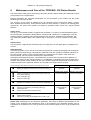
We recommend the following inspection and maintenance work
Simple cleaning:
Wiping off splashed chemicals from the outer surface. [1]
Heavy strain
Whenever required in
operation
Normal strain
Whenever required in
operation
Sight check:
Check for leakage in the area of the dosing system. [2]
Is the piston tight? [3]
Is the valve tight? [4]
Titration to clear? [5]
Weekly, when putting
back into operation
Monthly, when putting
back into operation
Basic cleaning of the dosing system:
All parts of the dosing system to be cleaned separately. [6]
Every three months
Whenever necessary
Technical inspection:
Check for air bubbles in the dosing system. [7]
Visual inspection
Check of the electrical connections. [8]
Semi-annually when
putting back into
operation
Semi-annually when
putting back into
operation
Semi-annually
Annually
Verification of the volume according to ISO 8655:
Perform basic cleaning
Inspection according to ISO 8655 Part 6 or Part 7. [9]
Please note: Depending on the respective application, there may be different specifications for the
entirety of the inspection and maintenance work to be performed. The individual intervals may be
extended if no complaints occur, but they will have to be shortened again as soon as any problem has
arisen.
Kapitel
8 Lagerung
Transport
Chapter
Kapitel
710
Wartung
- Recycling
undund
Pflege
and
Disposal
des Titrators
108
The inspection of the metrological reliability including maintenance work is offered as a service by SI
Analytics GmbH (including a manufacturer’s certificate, if so ordered). For this purpose, the titration
device is to be sent in to SI Analytics GmbH.
Detailed description of the inspection and maintenance work:
[1]
Wipe off using a soft cloth (and some water with a normal household detergent).
[2]
Leaking connections can be identified by moisture or crystals at the threaded connections of
the hoses, at the sealing lips of the piston inside the dosing cylinder or at the valve.
[3]
If any liquid becomes visible below the first sealing lip, it has to be checked at short timely
intervals whether any liquid will build up under the second sealing lip, too. In this case both the
piston and the glass cylinder have to be replaced immediately. It is easily possible that in
operation small liquid droplets build up under the first sealing lip, but they may also disappear
again. This phenomenon alone is no reason for replacement.
[4]
The valve has to be removed from its housing for inspection. In this process, the hoses remain
connected to the valve. Please check for moisture underneath the valve. When reinserting the
valve, please make sure that the small cam at the rotating axis is fitted into the corresponding
groove again.
[5]
The titration tip must be free of sedimentation or crystals which might obstruct the dosing
process or falsify the results.
[6]
Remove the cylinder, take the valve out of the valve housing, unscrew the hoses and then
rinse all parts carefully with distilled water. For the assembly of the cylinder, hoses and other
parts of the interchangeable unit, please refer to the operating instructions.
[7]
Dose one burette volume, then refill. Air bubbles will gather at the tip of the cylinder and in the
titration hose where they can be detected easily. If bubbles become visible, please re-tighten
all connections finger tight, and then repeat dosing. If air bubbles still remain within the
system, [6] please check the valve and replace the hose connections. The air bubbles may
also occur at the interface between the sealing lip of the piston and the cylinder. If a reduction
of the filling speed will not do, the dosing unit has to be replaced.
[8]
Check the electrical plug contacts for corrosion and mechanical damage. Defective parts have
to be repaired or replaced by new parts.
[9]
Please refer to the application “Burette inspection according to ISO 8655 Part 6”.
9
Storage and transportation
®
If the TITRONIC 500 Piston Burette or the interchangeable units have to be stored over some time,
or to be dislocated, the use of the original packing will be the best protection of the devices. However,
in many cases this packing will not be available any more, so that one will have to compose an
equivalent packaging system. Sealing the lower section in a foil is hereby recommended.
The devices should be stored in a room with a temperature between +10 and +40°C, and the (relative)
humidity of the air should not exceed 70 %.
If the interchangeable have to be stored over some time, or to be dislocated, the fluids inside the
system, especially aggressive solution have to be removed (please refer also to chapter 8.
®
„Maintenance and Care of the TITRONIC 500 Piston Burette”).
10
Recycling and Disposal
The present piston burette and it's packaging are manufactured as far as possible from materials
which can be disposed of environmental-friendly and recycled in a technically appropriate manner.
Please note: The main printed board carries a lithium battery. Batteries should not to be disposed of
with the normal domestic waste. They will be taken back and recycled or disposed of properly by the
manufacturer at no cost.
Should you have any questions regarding disposal, please contact SI Analytics.
Kapitel
8 Lagerung
Kapitel
11 Transport
Index
Kapitel
7 Wartung
undund
Pflege
des Titrators
11
109
Index
analytical balance 65
change method parameters 87
copy methods 86
delete methods 86
device address 97
Device Information 100
Display 75
Disposal 108
Documentation 94
Dosing accuracy 61
Dosing parameters 92
dosing speed 93
edit method 85
external PC Keyboard 76
Formula Selection 88, 89
Formula unit 91
Formulae for manual titration 88
Formulae for the Preparation of Solutions 89
Front Keyboard 75
interchangeable units 108
Interchangeable units 61
Interrupted use 107
Main Menu 79
manual controller 76
manual controller TZ 3880 („Mouse“) 65
Manual Titration 79
max. dosing-/titration volume 92
Method name 85
method parameters 85
new method 85
Password 99
printer 65
RESET 99
RS232 Settings 97
safety information 62
Sample description 93
Sample weight and volume (sample quantity)
90
Software Update 101
standard methods 85
storage 108
System Settings 95
System sounds 100
transportation 108
Unpacking and First Operation 63
USB Barcode scanner 65
USB Hub 65
USB stick 65
Viscosity 60
Warning 62
Notes:
Notes:
Notes:
TITRONIC® 500
Typ / type / type / tipo
Bescheinigung des Herstellers
Wir bestätigen, dass das oben genannte Gerät gemäß
DIN EN ISO 9001, Absatz 8.2.4
„Überwachung und Messung des Produkts“ geprüft wurde und dass die festgelegten
Qualitätsanforderungen an das Produkt erfüllt werden.
Supplier’s Certificate
We certify that the above equipment has been tested in accordance with DIN EN ISO 9001, Part 8.2.4
”Monitoring and measurement of product” and that the specified quality requirements for the product
have been met.
Certificat du fournisseur
Nous certifions que le produit a été vérifié selon DIN EN ISO 9001, partie 8.2.4 ”Surveillance et
mesure du produit” et que les exigences spécifiées pour le produit sont respectées.
Certificado del fabricante
Telefon +49 (0)6131 66-5111
Telefax +49 (0)6131 66-5001
www.si-analytics.com
E-Mail: [email protected]
Printed in Germany
SI Analytics GmbH
Postfach 24 43
55014 Mainz
Hattenbergstraße 10
55122 Mainz
Deutschland, Germany, Allemagne, Alemania
EDV
Version: 110901 US
Certificamos que el aparato arriba mencionado ha sido controlado de acuerdo con la norma
DIN EN ISO 9001, sección 8.2.4 „Seguimiento y medición del producto“ y que cumple con los requisitos
de calidad fijados para el mismo.