1
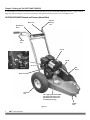
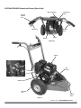
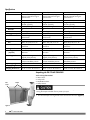
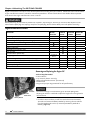
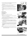
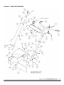
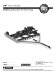
® ` DR STUMP GRINDER SAFETY & OPERATING INSTRUCTIONS Serial No. Order No. Original Language DR Power Equipment Toll-free phone: 1-800-DR-OWNER (376-9637) Fax: 1-802-877-1213 Website: www.DRpower.com Read and understand this manual and all instructions before operating the DR STUMP GRINDER. Table of Contents Chapter 1: General Safety Rules............................................................................................................................................................ 3 Chapter 2: Setting Up The DR STUMP GRINDER ............................................................................................................................... 6 Chapter 3: Operating The DR STUMP GRINDER ................................................................................................................................ 11 Chapter 4: Maintaining The DR STUMP GRINDER............................................................................................................................. 14 Chapter 5: Troubleshooting .................................................................................................................................................................. 22 Chapter 6: Parts Lists, Schematic Diagrams And Warranty ................................................................................................................ 24 Conventions used in this manual This indicates a hazardous situation, which, if not avoided, could result in death or serious injury. This indicates a hazardous situation, which, if not avoided, could result in minor or moderate injury. This information is important in the proper use of your machine. Failure to follow this instruction could result in damage to your machine or property. Serial Number and Order Number A Serial Number is used to identify your machine and is located on the Serial Number Label on your machine. An Order Number is used to check and maintain your order history and is located on the upper left portion of your packing slip. For your convenience and ready reference, enter the Serial Number and Order Number in the space provided on the front cover of this manual. Additional Information and Potential Changes DR Power Equipment reserves the right to discontinue, change, and improve its products at any time without notice or obligation to the purchaser. The descriptions and specifications contained in this manual were in effect at printing. Equipment described within this manual may be optional. Some illustrations may not be applicable to your machine. 2 DR® STUMP GRINDER Chapter 1: General Safety Rules Read this safety & operating Instructions manual before you use the DR STUMP GRINDER. Become familiar with the operation and service recommendations to ensure the best performance from your machine. If you have any questions or need assistance, please contact us at www.DRpower.com or call toll-free 1-800-DR-OWNER (376-9637) and one of our Technical Support Representatives will be happy to help you. Labels Your DR STUMP GRINDER carries prominent labels as reminders for its proper and safe use. Shown below are copies of all the Safety and Information labels that appear on the equipment. Take a moment to study them and make a note of their location on your STUMP GRINDER as you set up and before you operate the unit. Replace damaged or missing safety and information labels immediately. #137581 #235451 #257091 #153451 #193201 #264881 #188871 Protecting Yourself and Those Around You This is a high-powered machine, with moving parts operating with high energy. You must operate the machine safely. Unsafe operation can create a number of hazards for you, as well as anyone else in the nearby area. Always take the following precautions when using this machine: Keep in mind that the operator or user is responsible for accidents or hazards occurring to other people, their property, and themselves. Always wear protective goggles or safety glasses with side shields while using the STUMP GRINDER to protect your eyes from possible thrown debris. Avoid wearing loose clothing or jewelry, which can catch on moving parts. We recommend wearing gloves while using the STUMP GRINDER. Be sure your gloves fit properly and do not have loose cuffs or drawstrings. Wear shoes with non-slip treads when using your STUMP GRINDER. If you have safety shoes, we recommend wearing them. Do not use the machine while barefoot or wearing open sandals. Wear long pants while operating the STUMP GRINDER. Use ear protectors or ear plugs rated for at least 20 dba to protect your hearing. Keep bystanders at least 50 feet away from your work area at all times. Stop the engine when another person or pet approaches. CONTACT US AT www.DRpower.com 3 Safety for Children and Pets Tragic accidents can occur if the operator is not alert to the presence of children and pets. Children are often attracted to the machine and the grinding activity. Never assume that children will remain where you last saw them. Always follow these precautions: Keep children and pets at least 50 feet from the working area and ensure they are under the watchful care of a responsible adult. Be alert and turn the machine off if children or pets enter the work area. Never allow children to operate the STUMP GRINDER. Safety with Gasoline - Powered Machines Gasoline is a highly flammable liquid. Gasoline also gives off flammable vapor that can be easily ignited and cause a fire or explosion. Never overlook the hazards of gasoline. Always follow these precautions: Never run the engine in an enclosed area or without proper ventilation as the exhaust from the engine contains carbon monoxide, which is an odorless, tasteless, and deadly poisonous gas. Store all fuel and oil in containers specifically designed and approved for this purpose and keep away from heat and open flame, and out of the reach of children. Replace rubber fuel lines and grommets when worn or damaged and after 5 years of use. Fill the gasoline tank outdoors with the engine off and allow the engine to cool completely. Don't handle gasoline if you or anyone nearby is smoking, or if you're near anything that could cause it to ignite or explode. Reinstall the fuel tank Cap and fuel container cap securely. If you spill gasoline, do not attempt to start the engine. Move the machine away from the area of the spill and avoid creating any source of ignition until the gas vapors have dissipated. Wipe up any spilled fuel to prevent a fire hazard and properly dispose of the waste. Allow the engine to cool completely before storing in any enclosure. Never store a machine that has gas in the tank, or a fuel container, near an open flame or spark such as a water heater, space heater, clothes dryer or furnace. Never make adjustments or repairs with the engine running. Shut down the engine, disconnect the spark plug wire, keeping it away from the spark plug to prevent accidental starting, wait 5 minutes before making adjustments or repairs. Never tamper with the engine’s governor setting. The governor controls the maximum safe operation speed and protects the engine. Over-speeding the engine is dangerous and will cause damage to the engine and to the other moving parts of the machine. If required, see your authorized dealer for engine governor adjustments. Keep combustible substances away from the engine when it is hot. Never cover the machine while the muffler is still hot. Do not operate the engine with the air cleaner or the carburetor air intake cover removed. Removal of such parts could create a fire hazard. Do not use flammable solutions to clean the air filter. The muffler and engine become very hot and can cause a severe burn; do not touch. 4 DR® STUMP GRINDER General Safety Operating this Stump Grinder safely is necessary to prevent or minimize the risk of death or serious injury. Unsafe operation can create a number of hazards for you. Always take the following precautions when operating this Stump Grinder: Your Stump Grinder is a powerful tool, not a plaything. Exercise extreme caution at all times. The machine is designed to grind stumps. Do not use it for any other purpose. Know how to stop the Stump Grinder quickly; see “stopping the engine” in chapter 3. Never operate your unit on a slippery, wet, muddy, or icy surface. Exercise caution to avoid slipping or falling. See manufacturer’s instructions for proper operation and installation of accessories. Only use accessories approved by DR Power Equipment. Never use the machine without ensuring that all guards and shields are in place. Never, under any conditions, remove, bend, cut, fit, weld, or otherwise alter standard parts on the Stump Grinder. This includes all shields and guards. Modifications to your machine could cause personal injuries and property damage and will void your warranty. Allow only one person to operate the Stump Grinder at any time. If the machine should start making an unusual noise or vibration, shut down the engine, disconnect the spark plug wire, keeping it away from the spark plug to prevent accidental starting, wait 5 minutes, then inspect for damage. Vibration is generally a warning of trouble. Check for damaged parts and clean, repair and/or replace as necessary. Never tamper with safety devices. Check their proper operation regularly. Before performing any maintenance or inspection procedure on the Stump Grinder, release the throttle lever first and then release the operator presence lever, turn the ignition switch to “off”, remove the spark plug wire and keep it away from the spark plug. Never allow people who are unfamiliar with these instructions to use the Stump Grinder. Allow only responsible individuals who are familiar with these rules of safe operation to use your machine. Never overload or attempt to grind material beyond the manufacturer’s recommendation. Personal injury or damage to the machine could result. While using the Stump Grinder, don't hurry or take things for granted. When in doubt about the equipment or your surroundings, stop the machine and take the time to look things over. Never operate the machine when under the influence of alcohol, drugs, or medication. Use the machine only in daylight. Stay alert for hidden hazards or traffic. Keep all nuts and bolts tight and keep the equipment in good operating condition. A Note to All Users Under California law, and the laws of some other states, you are not permitted to operate an internal combustion engine using hydrocarbon fuels without an engine spark arrester. This also applies to operation on US Forest Lands. All DR® STUMP GRINDERS shipped to California, New Mexico and Washington State are provided with spark arresters. Failure of the owner or operator to maintain this equipment in compliance with state regulations is a misdemeanor under California law and may be in violation of other state and/or federal regulations. Contact your State Park Association or the appropriate state organization for specific information in your area. No list of warnings and cautions can be all-inclusive. If situations occur that are not covered by this manual, the operator must apply common sense and operate this DR STUMP GRINDER in a safe manner. Contact us at www.DRpower.com or call 1-800DR-OWNER (376-9637) for assistance. CONTACT US AT www.DRpower.com 5 Chapter 2: Setting Up The DR STUMP GRINDER It may be helpful to familiarize yourself with the controls and features of your DR STUMP GRINDER as shown in Figure 1 before beginning these procedures. If you have any questions at all, please feel free to contact us at www.DRpower.com. DR STUMP GRINDER Controls and Features (Manual Start) Operator Presence Lever Brake Lever Maintenance Meter Throttle Lever Gas Fill Choke Lever Oil Fill Fuel Shut-off Belt Guard Starter Cord Pneumatic Tires “On” “Off” Ignition Switch (6HP) (This Switch is Disconnected on 9HP Manual Start Models and not Needed for Starting) Carbide Teeth Figure 1a 6 DR® STUMP GRINDER DR STUMP GRINDER Controls and Features (Electric Start) “Start” Key Switch Operator Presence Lever Brake Lever Maintenance Meter Throttle Lever Battery Oil Fill REAR VIEW Gas Fill Choke Lever Belt Guard Fuel Shut-off Starter Cord Pneumatic Tires Carbide Teeth Figure 1b CONTACT US AT www.DRpower.com 7 Specifications Engine 6HP Subaru Manual-Start Please refer to the Engine Owner’s Manual for Enginespecifications. 9HP Subaru Manual-Start Please refer to the Engine Owner’s Manual for Enginespecifications. 9HP Subaru Electric-Start Please refer to the Engine Owner’s Manual for Enginespecifications. Tire Size Handle Bars 14.5" Pneumatic Height adjustable to 32", 36.5" and 40" (w/tools) 14.5" Pneumatic Height adjustable to 32", 36.5" and 40" (w/tools) 14.5" Pneumatic Height adjustable to 32", 36.5" and 40" (w/tools) Brake Diameter Clutch Engagement speed Frame Band w/ locking feature 4" Centrifugal 1900 RPMs Welded 12 ga steel construction Band w/ locking feature 4" Centrifugal 1900 RPMs Welded 12 ga. steel construction Band w/ locking feature 4" Centrifugal 1900 RPMs Welded 12 ga. steel construction Belt Size Construction V-Belt AP47: 49.3" OD, 47.3" ID Wrapped for abrasion resistance V-Belt BP47: 49.8" OD, 47.3" ID Wrapped for abrasion resistance V-Belt BP47: 49.8" OD, 47.3" ID Wrapped for abrasion resistance Cutting Head Cutting Head Size (w/Teeth) Rotary 9 Tooth 1.3" Wide (kerf) X 10.5" Diameter Rotary 9 Tooth 1.3" Wide (kerf) X 10.5" Diameter Rotary 9 Tooth 1.3" Wide (kerf) X 10.5" Diameter Replaceable Tungsten Carbide Tipped (three position) Replaceable Tungsten Carbide Tipped (three position) 28" W x 51" L x 36" H* *center Handlebar position 139 lbs 204 lbs. 54.75" L x 35.5" W x 45.25" H Replaceable Tungsten Carbide Tipped (three position) Cutting Teeth Machine Dimensions 28" W x 51" L x 36" H* *center Handlebar position Operating Weight Shipping Weight Shipping Dimensions 127 lbs 192 lbs. 54.75" L x 35.5" W x 45.25" H 28" W x 51" L x 36" H* - *center Handlebar position 160 lbs 225 lbs. 54.75" L x 35.5" W x 45.25" H Unpacking the DR STUMP GRINDER Box Cover Straps Tools and supplies Needed: Wire Cutters Utility Knife Needle Nose Pliers Safety Glasses The Straps and Cable Ties may be under tension. Wear Safety Glasses when cutting the Straps and Cable Ties to protect your eyes. 1. Cut the two Straps securing the Box Cover and remove the Cover (Figure 2). Figure 2 8 DR® STUMP GRINDER 2. Pull the seams at the ends of the Box apart (you may need Needle Nose Pliers to loosen the staples) and lay the sides down (Figure 3). Box Seams Safety and Operating Instructions Manual 3. Remove the Product Package (Safety and Operating Instructions manual and Engine manual) from the Control Panel by cutting the tape with a Utility Knife. 4. Cut all Plastic Straps that are securing the Stump Grinder to the Pallet, unlock the Brake by pressing it and roll the Stump Grinder from the Pallet (Figure 4). Do not discard the shipping materials until you are fully satisfied with your new DR® STUMP GRINDER. Adding Oil and Gasoline Engine Oil SAE 30: above 50 degrees F; 10w-30: 10-90 degrees F; 5w-30: 30 degrees F or below Fuel Unleaded gasoline You must add oil before starting the engine. This machine is shipped without oil. Traces of oil may be in the reservoir from factory testing, but you must add oil before starting the engine. Fill the reservoir slowly, checking the level frequently to avoid overfilling. To get an accurate reading when checking the oil level: - The Engine must be level. - The dipstick should not be screwed down to ensure an accurate oil level reading. Figure 3 Cable Ties Figure 4 Full Low NOTE: Use only the recommended high detergent engine oil. Other types of oil could cause problems operating your machine. Please refer to your Engine Owner’s Manual for detailed oil information. 1. Position the machine so the Frame and Engine are level. Remove the Oil Fill/Dipstick (Figure 5) and clean the end of it with a rag. The Frame and Engine must be level to get an accurate reading when adjusting the oil level. Use blocks to adjust the height of the cutting head to level the Frame. 2. Machines are shipped with no oil. Initially add 16 oz. of the oil recommended by the Engine Manufacturer. Wait one minute for the oil to settle. Oil Fill/Dipstick Figure 5 3. Replace the Dipstick, but DO NOT screw it in to ensure an accurate reading and then remove it to check the oil level (clean the Dipstick with the rag after checking). 4. Continue adding a few ounces of oil at a time, rechecking the Dipstick until the oil reaches the fill mark. Be careful not to overfill. 5. Replace the Dipstick and screw all the way down when full. CONTACT US AT www.DRpower.com 9 Gas Fill Cap 6. Remove the Gas Fill Cap and fill the Gas Tank with fresh, unleaded gas (with a minimum of 85 Octane) to approximately 1" to 1-1/2" below the top of the fill neck to allow for fuel expansion (Figure 6). Be careful not to overfill and reinstall the Gas Fill Cap before starting the engine. See your Engine Owner’s Manual for more detailed information. NOTE: To refill the gas tank, turn the engine OFF and let the engine cool at least five minutes before removing the gas fill cap. Remove any blocking used to level the Engine before operating the DR Stump Grinder. Figure 6 Check the Tire Pressure Tools Needed: Tire Pressure Gauge Air Compressor 1. Remove the Valve Stem Protective Cap (Figure 7) and check the tire pressure Valve Stem Protective Cap with a Tire Pressure Gauge. 2. Check what the manufacturers recommended pressure is that is stamped on the side of the Tire. 3. If the pressure is too low, add air through the Valve Stem with an air hose. Figure 7 4. Replace the Valve Stem Protective Cap when finished. Do not over inflate the tires. Inflate to the manufacturers recommended pressure found on the tires. Connect the Battery Negative Terminal Battery Figure 8 10 DR® STUMP GRINDER NOTE: The Battery may have been shipped with a protective Cap over the negative Terminal and the Cap will need to be removed to connect the Negative Wire. 1. Connect the Black Negative Terminal onto the negative Battery Lug (Figure 8). Chapter 3: Operating The DR STUMP GRINDER It may be helpful to better familiarize yourself with the features of your Stump Grinder by reviewing Figure 1 in Chapter 2 before beginning the steps outlined in this chapter. Operator Presence Lever Read and understand the warnings listed in “Chapter 2 General Safety Rules” before operating this Stump Grinder. Control Levers 1. Familiarize yourself with all of the Control Levers and their functions before Brake Lever Throttle Lever Figure 9 operating the Stump Grinder (Figure 9). Starting the Engine (Manual Start) Ignition Switch 2. Turn the Ignition Switch to the “ON” position (Figure 10) (6HP only). Off 3. Make sure the Fuel Shut-off is in the “OPEN” position (Figure 11). 4. Move the Choke Control Lever to the left to the choke position (leave in the run position to the right if the engine is already warm). On NOTE: The Operator Presence Lever must be held down for the Engine to start and continue running. If you need to stop the machine quickly for any reason, let go of the Operator Presence Lever. 5. Hold down the Operator Presence Lever and slowly pull the Starter Cord until you feel resistance, then pull quickly. The Cord will recoil back into position. Figure 10 6. As the engine warms up, slowly adjust the Choke to the right towards the run position. Wait until the engine runs smoothly before each Choke adjustment. Choke Lever 7. When the Engine is warmed up and running smoothly, ensure that the Choke is fully in the run position to the right. Starting the Engine (Electric Start) Fuel Shut-off 1. Make sure the Fuel Shut-off is in the “OPEN” position (Figure 11). 2. Move the Choke Control Lever to the left to the choke position (leave in the run position to the right if the engine is already warm). NOTE: The Operator Presence Lever must be held down for the Engine to start and continue running. If you need to stop the machine quickly for any reason, let go of the Operator Presence Lever. Figure 11 CONTACT US AT www.DRpower.com 11 Key Switch 3. Hold down the Operator Presence Lever and turn the Key Switch fully to the “Start” position until the engine starts (Figure 12). The Key will move back a bit from the full Start position when released. 4. As the engine warms up, slowly adjust the Choke to the right towards the run position. Wait until the engine runs smoothly before each Choke adjustment. 5. When the Engine is warmed up and running smoothly, ensure that the Choke is fully in the run position to the right. Stopping the Engine Figure 12 1. Slowly release the Throttle Control Lever to the idle position (Figure 9). 2. Release the Operator Presence lever to stop the Engine. 3. Turn the Ignition Switch to the “Off” position (Figure 10 for 6HP Manual Start) and to the left (Figure 12 for 9HP Electric Start). Before You Begin Dig away the earth and remove any stones near the tree stump that may interfere with your work. Check that the ground is free of foreign objects, such as electrical cables, barbed wire, etc. Cut the stump as close to the ground as possible using a Chainsaw before using the Stump Grinder. 12 DR® STUMP GRINDER Grinding Stumps These grinding instructions are basic guidelines. Try different techniques in direction and depth of cut to determine what works best for your situation. Brake Lever Read and understand the warnings listed in “Chapter 2 General Safety Rules” before operating this Stump Grinder. 1. Start the Engine as described in the “Starting the Engine” section on the Start at Right-Hand Side of Stump previous page. 2. Allow engine to warm up at idle for a few minutes. 3. Move the Stump Grinder into position with the Cutter Head at the right side Figure 13 of the stump on the edge closest to you (not touching) near the top edge (Figure 13). 4. Lock the Hand Brake by pulling the Brake Lever, sliding the Lock forward and releasing the Lever. Always make sure the Teeth are not in contact with anything before operating the Throttle Lever. The Clutch will be damaged if the teeth are not free to turn as you start to press the Throttle. 5. Hold down the Throttle Lever on the right side Handlebar (this will engage the Cutter Head Rotation). Let the Cutter Head come up to speed. 6. Lower the Cutter Head approximately 1/2" to 1" into the front-top corner of the stump and slowly swing the Cutter Head to the left into the stump by pushing on the right hand handlebar (Figure 14). When you are finished the first pass through the Stump, swing the Cutter Head back to the starting position on the right side. Lower the Cutter Head approximately 1/2" to 1" and slowly swing the Cutter Head to the left through the Stump. Continue this process until you have removed the front portion of the stump to ground level. Figure 14 2 1 If the Engine bogs down, lift the Cutting Head away from the stump to allow the Cutting Head to come back up to speed before further cutting. Figure 15 7. Swing the Cutter Head over to the right side (Figure 15 arrow #1), advance the machine forward (arrow #2) by releasing and resetting the brake. The machine should only be advanced far enough to engage the Cutter Head into the stump so that when swept across the stump it will remove 1/2" to 1" of stump with each sweep. 8. Sweep the Cutter Head across the stump, cutting away 1/2" to 1" of stump. 9. Continue cutting and advancing until the top level of stump is all removed, making sure not to cut the stump deeper than ground level during this first stage. 10. Release the Throttle Lever and then the Operator Presence Lever to stop the Engine and wait ten seconds for Cutter Head to stop rotating. 11. Release the Brake so you can pull the machine away from the stump and remove the chips/debris and any dirt away from the stump. 12. Repeat steps 1 through 11 until the stump is removed to the desired depth. CONTACT US AT www.DRpower.com 13 Chapter 4: Maintaining The DR STUMP GRINDER Regular maintenance is the way to ensure the best performance and long life of your machine. Please refer to this manual and the engine manufacturer's owner's manual for maintenance procedures. Service intervals listed in the checklist below supersede those listed in the engine manufacturer's owner's manual. Before performing any maintenance procedure or inspection, stop the engine, wait five (5) minutes to allow all parts to cool. Disconnect the spark plug wire, keeping it away from the spark plug. Disconnect the Battery Terminals (Electric start only). Regular Maintenance Checklist PROCEDURE BEFORE EACH USE Check Engine Oil Level Check General Equipment Condition Check Cutting Teeth (are they dull or damaged) Clean Engine Exterior & Cooling Fins Remove debris wrapped around Cutter Head for Bearing protection. Check Tire Pressure Replace Belt if stretched or worn Clean Air Filter Lubricate Cables (SAE 30 Oil) Change Engine Oil Replace Cutting Teeth (or sooner if dull or damaged) Check Cutter Head when Teeth are replaced Replace Cutter Head (order kit # 271621) Replace Spark Plug Replace Air Filter EVERY 25 HOURS EVERY 60 HOURS EVERY 100 HOURS 1st time 5 hours Removing and Replacing the Engine Oil Tools and Supplies Needed: 14mm Wrench 1/2" Wrench (electric start only) Rags and approved Container (for waste oil) Small funnel Engine Oil (see your Engine Manual for Oil specifications) Battery Terminals Locknuts inside Frame The Frame and Engine must be level to get an accurate reading when adjusting the oil level. Use blocks to adjust the height of the cutting head to level the Frame. Battery Bracket Figure 16 1. For Electric Start machines you will first need to disconnect the Battery Terminals and remove the Battery Bracket by removing the two Locknuts from the Bracket Studs with a 1/2" Wrench (leave Battery attached to Bracket) (Figure 16). 14 DR® STUMP GRINDER 3. 4. 5. 6. Low Full 2. Position the machine so the Frame and Engine are level and place a Waste Oil Container under the Oil Drain Plug (Figure 17). Remove the Oil Drain Plug with a 14mm Wrench and let the Oil drain into the Container. Replace the Oil Drain Plug and remove the Oil Fill/Dipstick. Initially add 16 oz. of SAE 30 High Detergent oil (recommended by the Engine Manufacturer) into the Oil Fill and wait one minute for the oil to settle. Check the Dipstick and continue adding a few ounces of oil at a time, rechecking the Dipstick until the oil reaches the fill mark. Be careful not to overfill. 7. Replace the Battery Bracket for electric start machines and reconnect the Oil Drain Plug Oil Fill/Dipstick Battery. Figure 17 Replacing the Belt Tools and Supplies needed: Two 1/2" Wrenches 9/16" Wrench New DR Drive Belt (see chapter 6 for part numbers) Gloves 1. Remove the Bolt, Lock Washer and Flat Washer from the rear of the Belt Guard with a 1/2" Wrench (Figure 18). Bolt, Lock Washer and Flat Washer Bolt, Flat Washers and Locknut 2. Slightly loosen the Bolt, Washers and Lock Nut at the front of the Belt Guard with two 1/2" Wrenches and rotate the Guard forward. NOTE: You may need to pull out on the bottom edge of the Guard as you rotate the Belt Guard to clear the Frame. Figure 18 3. You should wear Gloves as you position a 9/16" Wrench onto the Idler Idler Pulley Pulley Bolt and inline with the Pulley Bracket (Figure 19). Pull the Wrench to rotate the Belt Tensioner away from the Belt and then remove the Belt from under the Idler Pulley. 4. Roll the Belt off the top of the Clutch Pulley by rotating the Cutting Head in the reverse direction as you guide the Belt off to the side at the top of the Pulley (Figure 19). Remove the Belt from around the Cutting Head Pulley (Figure 20). 5. Reverse the previous steps to install the new Belt and reinstall the Belt Guard. Belt Clutch Pulley Figure 19 NOTE: When installing the Belt onto the Clutch Pulley, Start the Belt onto the bottom of the Pulley and rotate the Cutting Head forward as you guide the Belt up over the top of the Pulley. Belt Cutting Head Pulley Figure 20 CONTACT US AT www.DRpower.com 15 Replacing the Wheels Tire Tools and Supplies needed: 1/2" Wrench 1. With the Stump Grinder on the ground, remove the Bolt, Lock Washer and Large Flat Washer from the Axle with a 1/2" Wrench (Figure 21). 2. Block the Stump Grinder up so the Wheels are off the ground and remove the Wheel. Bolt and Washer Figure 21 NOTE: The Wheel on the right hand side has a Bushing in each end of the Wheel Hub (make sure the Bushings are in place when installing the Wheel). The left hand Wheel has a Keyway built in with a key to hold it from spinning when the Brake is applied (make sure the Key is installed in the slot when installing the Wheel). 3. Reinstall the Wheel and secure with the Bolt, Lock Washer and large Flat Washer using a 1/2" Wrench. 16 DR® STUMP GRINDER Replacing the Cutting Teeth Tools and Supplies needed: Two 7/16" Wrenches Gloves CAUTION! Wear Gloves when working near the teeth. Without Gloves your hands could suffer cuts from the sharp Teeth. 1. Block the front end of the Stump Grinder so the Cutter Head is just off the ground. Bolt and Locknut 2. Remove the nine Bolts and Locknuts from the Cutter Head with two 7/16" Wrenches (Figure 22). 3. Move the Side Plates away from the Cutter Head Base to gain access to the Figure 22 Bolt Hole Teeth (Figure 23). 4. Remove a Cutter Tooth by sliding the Tooth to the side and pulling it away from the Cutter Head. Install a new Cutter Tooth that is the same as the one you removed (straight, left bend or right bend). 5. Continue removing and adding Teeth until they all are replaced. NOTE: The Teeth must be installed in the correct order - straight Tooth, left bend Tooth and then right bend Tooth, straight, left bend and then right bend etc. 6. When all the Cutter Teeth are in place, slide the Side Plates back against the Cutter Head. Tooth Slot Right Bend Tooth 7. Secure the Teeth by fastening the Side Plates to the Cutter Head the new nine Bolts and Locknuts that came with your Cutting Teeth Kit. CAUTION! Check wear of the Head Assembly each time the Teeth are replaced. Replace the Head Assembly if it is damaged or worn. Be sure to use the new Bolts and Locknuts provided with the replacement teeth. Failure to replace the Head Assembly when damaged or worn may result in Cutting Teeth coming loose and damaging the machine. Replacement Teeth Mounting Bolts must pass through the slot in the Teeth. Some Head Assemblies may have additional holes in between the Teeth that are not used. Cutter Head Base Left Bend Tooth Side Plate Figure 23 Side Plate Straight Tooth Do not over tighten the Bolts. They should be snug, about 100 inchpounds (8 foot-pounds). If Bolts are over tightened they may crack or break. The Teeth should fit securely and when pulled out straight towards the front of the machine (not rocking side to side) should not move more than 1/32". If it moves more than 1/32" the Cutter Head Tooth Key is worn and the Cutter Head should be replaced. CONTACT US AT www.DRpower.com 17 Replacing the Clutch Dead Blow Hammer Tools and Supplies needed: Clutch 1/2" Wrench (6HP) 5/8" Wrench (9HP) Dead Blow Hammer 1. Place a 1/2" Wrench (6HP) or 5/8" Wrench (9HP) onto the Clutch Bolt and rotate the Wrench counterclockwise until you feel some resistance (Figure 24). 2. Hit the Wrench with a Dead Blow Hammer to start the Bolt turning on the Engine Shaft. Figure 24 3. Remove the Bolt, Lock Washer, Large Flat Washer and Clutch from the Engine Shaft. 4. Apply a never seize type grease to the Engine Shaft and install the new Clutch (align the Clutch Key Slot with the Key on Engine Shaft) and secure with the Bolt, Lock Washer and Large Flat Washer using a 1/2" Wrench (6HP) or 5/8" Wrench (9HP). Lubricate Cables Supplies needed: SAE 30 Oil 1. Lubricate the ends of the Throttle and Brake Cables with SAE 30 Oil where Brake Hub the cable goes into the sheathing. 2. Work the Cable Levers to work the Oil in between the Cable and Sheathing. Adjusting the Handlebars Bolt, Lock Washer and Flat Washer Figure 25 Supplies needed: Two 9/16" Wrenches 1/2" Wrench 1. Remove the left Wheel as described in the “Replacing the Wheels” section. NOTE: The Brake Lever can be locked to aid in loosening the Hardware in the next step, but must be unlocked to remove the Brake Drum. 2. Remove the four Bolts, Lock Washers and Flat Washers from the Brake Handlebar Drum with a 1/2" Wrench and pull the Drum from the Axle (Figure 25). 3. Remove the bottom Bolt, Flat Washers and Locknuts from both Handlebars with two 9/16" Wrenches and just loosen the upper Hardware (Figure 26). 4. Rotate the Handlebars forward to adjust them higher or back to make them Bottom Bolt, Flat Washers and Locknut Figure 26 lower and align with the holes in the Frame. 5. Reinstall the bottom Bolt, Flat Washers and Locknuts into both Handlebars and tighten all Handlebar Hardware with two 9/16" Wrenches. 6. Reinstall the Brake Drum and Wheel on the left side of the machine. When the Handlebars are adjusted to the highest setting, you should change the position of the Exhaust Deflector so it is oriented 45º downward to the left so it is not pointing directly at the Handlebar. The paint may be damaged if the Deflector is not rotated. 18 DR® STUMP GRINDER Adjusting The Brake Tools and supplies needed: 1/2" Wrench Blocking Material Brake Cable NOTE: You must block the machine up so the left-side Wheel is just off the ground and can rotate freely to perform the following steps. Tightening the Brake Cable (if the Brake does not hold the Wheel in place) 1. Loosen the lower nut a few turns so it moves away from the Bracket (Figure 27). Adjusting Nuts Bracket Spring Figure 27 2. As you rotate the Wheel forward (with Wheel Lever unlocked), tighten the upper Nut until you feel a slight resistance at the Wheel. 3. Tighten the lower Nut up against the Bracket. 4. Lower the Stump Grinder to the ground and test the Brake and pivoting (side to side) action. 5. If the left-side Wheel rotates forward while the Brake Lever is locked, the Cable needs more tightening. Repeat steps above as needed. NOTE: When the Cable is adjusted correctly and the Brake Lever is locked, the left-side Wheel will still rotate in reverse (towards the operator) with some effort, but should not rotate forward. Loosening the Brake Cable (if the Brake does hold the Wheel in place, but pushing the machine with the Brake off is difficult) 6. As you rotate the Wheel forward (with Wheel Lever unlocked), loosen the upper Nut until the Wheel turns more freely but you still feel a slight resistance at the Wheel (Figure 27). 7. Tighten the lower Nut up against the Bracket. 8. Lower the Stump Grinder to the ground and test the Brake and pivoting (side to side) action. 9. If the left-side Wheel holds when the Brake is applied, but the machine is Loosen 1/4 Turn hard to push ahead when the Brake is released, the Cable needs more loosening. Repeat steps above as needed. Adjusting The Throttle Linkage Throttle Pivot Nut Over time friction may increase in the Throttle Linkage. If the throttle lever does not return fully to low idle the throttle Pivot Nut may need adjustment. Tools needed: 10mm Socket Ratchet and Extension 1. Loosen the Throttle Pivot Nut 1/4 turn counterclockwise and test the Throttle Lever (Figure 28). If the Throttle Lever fully returns to low idle, it is working properly. If there is still some hesitation of the Throttle Lever fully returning to low idle, turn the Throttle Pivot Nut another 1/4 turn and retest as needed. NOTE: The Throttle Pivot Nut should not be loosened to the point that the Throttle Linkage is too loose (has excessive play). If the problem persists please contact us at www.DRpower.com or call 1-800-DR-OWNER (376-9637) for assistance. Figure 28 CONTACT US AT www.DRpower.com 19 Battery Care (For Electric-Starting Models Only) Proper care can extend the life of a Battery. Follow these recommendations to ensure your Battery’s best performance and long life: Do not allow the Battery charge to get too low. If the machine is not used, charge the Battery every 4 – 6 weeks. Operate the engine for at least 45 minutes to maintain proper Battery charge. Store an unused Battery in a dry environment with temperatures between +40°F (+5°C) and +95°F (+35°C). Make sure the storage temperatures will never be outside of these limits. The lower the storage temperature is within the specified temperature, the better as the battery will discharge more slowly at low temperatures. Do not charge an already charged Battery. In theory, you cannot overcharge our Battery with a trickle charger; however, when a Battery is fully charged and the charger is still on, it generates heat that could be harmful to the Battery. A fully charged Battery will read 12V-13.2V with a voltmeter. Do not continue to crank your Engine when the Battery charge is low. Charging the Battery When you are finished charging the battery, disconnect the charger from the outlet first, then disconnect the battery charger wires from the battery. If you leave the battery charger wires connected to the battery, the battery will discharge itself back into the charger. Operate the Engine for at least 45 minutes to maintain proper Battery charge. If the Battery loses its charge, you will need to use a trickle charger (like the DR Battery Charger) to recharge it. The Charger should have an output of 12 volts DC at no more than 2 amps. At 1 amp the Battery may need to be charged for as long as 48 hours. At 2 amps, the Battery may need to be charged for as long as 24 hours. NOTE: Using the Recoil Starter and then running the Engine will not recharge a dead or significantly discharged Battery. To connect a Battery Charger to your DR STUMP GRINDER, follow the steps listed below. 2. Attach the Black (-) alligator clipped wire from the Charger Adapter to the Negative (-) terminal of the Battery, then attach the Red (+) alligator clipped wire to the Positive (+) Battery terminal. 3. Plug the Charger into a standard wall outlet. 20 Typically, the Battery takes between 6 and 8 hours to fully charge. Do not leave the charger on the battery longer than 24 hours for a 2 amp charger, or 48 hours for a 1 amp charger as you could potentially damage the battery.. You can charge the Battery many times. The Battery lasts longer if you charge it before it is fully drained. Keep it fully charged and at room temperature when not using your DR STUMP GRINDER. If the Battery does not hold its charge for very long under normal conditions or it simply won’t hold a charge, then replace it. You can purchase replacement Batteries directly from us. To install your new Battery, follow the directions on the next page. DR® STUMP GRINDER Replacing the Battery Tools Needed: Two 7/16" Wrenches 1. Disconnect the Battery Terminals (Figure 29). 2. Remove the Bolts and Locknuts that secure the Battery Clamp using two 7/16" Wrenches. 3. Remove the Clamp and the dead Battery. 4. Install the new Battery. Battery Clamp Bolts and Locknuts 5. Install the Battery Clamp and secure with the Bolts and Locknuts using two 7/16" Wrenches. 6. Attach the Battery Terminals. Black Wire to negative black Terminal and Red Wire to positive red Terminal. Battery Terminals Figure 29 Disposing of the Battery Responsibly (Electric-Start Models) The Battery is a sealed lead-acid Battery. Recycle or dispose of it in an environmentally sound way. Do not dispose of a lead-acid Battery in a fire; the Battery may explode or leak. Do not dispose of a lead-acid Battery in your regular, household trash. Law in most areas prohibits incinerating, disposing in a landfill, or mixing a sealed lead-acid Battery with household trash. Recycling a Used Battery Please dispose of your used Batteries responsibly by recycling them. Call your local Solid Waste Management District or your local waste handler to locate the collection site nearest you. Some collection sites recycle Batteries year-round; others collect them periodically. You can also visit the Web site of Earth 911 for more information [www.earth911.org]. Once there, click the Municipal HHW link under Hazardous Household Waste, and enter your zip code. The site lists recycling centers located near you. For a fee, you can recycle your Batteries with the International Metals Reclamation Company. Visit them at www.inmetco.com and click Services; or contact them at: INMETCO PO Box 720 245 Portersville Road Ellwood City, PA 16117 (724) 758-2825; fax (724) 758-2845 To learn more about hazardous waste recycling, visit the Web site for Battery Council International [www.batterycouncil.org] or for the Environmental Protection Agency [www.epa.gov]. CONTACT US AT www.DRpower.com 21 Chapter 5: Troubleshooting Most problems are easy to fix. Consult the Troubleshooting Table below for common problems and their solutions. If you continue to experience problems, contact us at www.DRpower.com or call toll-free 1-800-DR-OWNER (376-9637) for support. Set the Wheel Brake, shut down the engine, remove the spark plug wire and wait 5 minutes before performing any maintenance procedure or inspection on the Stump Grinder. Troubleshooting Table SYMPTOM POSSIBLE CAUSE Recoil will not pull out or is difficult to pull. There may be an oil compression lock in the cylinder. Take out the Spark Plug; hold a rag over the Spark Plug hole and pull the Recoil Cord several times to blow out any oil in the Cylinder. Wipe off the Spark Plug and reinstall it. Check the Engine oil level; the Engine may be seized. The Recoil may be broken or jammed. Visit our website at www.DRpower.com. The Engine will not start. Make sure the Operator Presence Lever is held down and that the Ignition Switch is in the RUN position (Manual Start), or the Key is inserted into the Key switch and rotated to the right (Electric Start). Check the oil and gas level. Make sure that the Fuel Shut-Off is in the ON position. Check that the Spark Plug Wire is attached. The Air Filter may be dirty; change it following the procedure in the Engine Owner’s Manual. The gas may be old; change it if necessary. Use a fuel stabilizer if you keep gas longer than one month. Check the Throttle and Choke settings, adjustment and travel. The Spark Plug may be dirty or cracked; change it if necessary. If it’s oily, leave it out, hold a rag over the Plug Hole and pull the Recoil Cord several times to blow out any oil in the Cylinder, then wipe off the Plug and reinsert it. Check the wire connections—especially the ground connections to the Engine and the Starter connections. Check to be sure that all of the connections are clean and tight. The Battery may not be charged. Check the voltage yourself or at a Service Station. If it is low, charge it with a 12-volt, 1 to 2 amp trickle Charger. If you do not use your machine for at least 45 minutes at a time, the Battery may need to be periodically charged. See the “Battery Care “section in Chapter 4. If your Engine still won’t start, visit our website at www.DRpower.com. (Please refer to the Engine Owner’s Manual for Engine-specific procedures.) The Engine lacks power or is not running smoothly. (Please refer to the Engine Owner’s Manual for engine-specific procedures.) 22 DR® STUMP GRINDER Make sure the Choke Lever is all the way off. The Air Filter may be dirty; change it following the procedure in the Engine Owner’s Manual. The Spark Plug may be dirty or cracked; change it if necessary. The gas may be old; change it if necessary. Use a fuel stabilizer if you keep gas longer than one month. The Engine oil may be dirty. Change it if necessary. Check that the Cooling Fins are clean and free of debris. Clean as needed. If your Engine still lacks power, visit our website at www.DRpower.com. Troubleshooting Table (Continued) Set the Wheel Brake, shut down the engine, remove the spark plug wire and wait 5 minutes before performing any maintenance procedure or inspection on the Stump Grinder. SYMPTOM POSSIBLE CAUSE Engine smokes. The Engine runs well but the Cutting Head won’t move. The Throttle should be fully pressed to engage Clutch. The Cutter Head Drive Belt is off the pulleys or broken. Reinstall or change Belt (refer to “Chapter 4: Maintaining the DR Stump Grinder”). Confirm there is nothing wedged/ wrapped around cutter head, or Pulleys. Confirm the throttle is moving on the engine. Confirm that Belt has not stretched to a point that it is slipping off the Pulleys. Clutch is not working. Change Clutch (refer to “Chapter 4: Maintaining the DR Stump Grinder”). The Engine does not fully return to low idle when the throttle is released. Throttle linkage is sticking. Adjust throttle linkage (refer to “Chapter 4: Maintaining the DR Stump Grinder”) The Cutting Head is rotating but the cutting action is extremely slow and the stump is showing signs of excessive heat. The teeth are dull or damaged. Replace Teeth (refer to “Chapter 4: Maintaining the DR Stump Grinder”). Belt falls off Pulleys frequently. Check Pulleys and Belt for damage. Check tightness of Idler Arm Pivot Bolt. Left-side Wheel turns forward when Brake Lever is locked or machine is difficult to push when Brake Lever is released. Brake Cable needs adjusting. Adjust Cable as needed (refer to “Chapter 4: Maintaining the DR Stump Grinder”). Check the oil level and adjust as needed. Clean the Engine cooling fins and the carburetor housing if they are dirty. The Air Filter may be dirty; change it following the procedure in the Engine Owner’s Manual. You may be using the wrong oil. Refer to your Engine Owner’s Manual for detailed information. If the Engine still smokes, visit our website at www.DRpower.com. CONTACT US AT www.DRpower.com 23 Chapter 6: Parts Lists, Schematic Diagrams And Warranty Parts List - HANDLEBAR ASSEMBLY NOTE: Part numbers listed are available through DR Power Equipment. Ref# Part# Description Ref# Part# Description 01 02 03 04 05 06 07 08 09 10 11 12 13 14 15 16 17 18 Cross Member, Handlebar, w/Labels Bolt, 5/16-18 x 1-1/2" Nut Nylon Lock 5/16-18 Label, Control Panel Front Plug, Control Panel, With Cutout Lever, Op Presence, w/ Wire Lever, Brake, w/ Lock Grip, Ergonomic, 1" Grip, 1" Throttle Screw, #10 x 1-1/2", Type A Handlebar, Right, w/Label Bolt, Hhcs, 3/8-16 x 1-1/4", Gr5 Washer, Flat, 5/16", Uss Handlebar, Left Nut, Nylon Lock, 3/8-16 Bolt, Hcs, 3/8-16 x 2-1/4", Full Thread Cable Tie, 7 1/2" 19 20 21 22 23 24 25 26 27 28 29 30 31 32 33 34 35 Bracket, Brake Cable Bolt, Tri-Lobe, 1/4-20 x 1/2" Guard, Debris Bolt, Hcs, 5/16-18 x 1", Gr 5, Zp Washer, Flat, 1/4", Uss Frame, w/Labels Label, Head Rotation Label, DR Logo, 6" Round Label, CHP Address Cable, Brake Label, Throttle Control Meter, Hour/RPM/Maintenance Switch, Start Label, Start Keys Screw, M4 x 8mm Washer, Lock, M4 24 271731 134431 110761 265191 179291 180691 165181 164951 164961 264801 111631 265291 150431 112411 247291 110751 157121 112141 DR® STUMP GRINDER 264791 179121 264761 111581 112381 271721 264881 234941 235451 264781 153451 217201 265041 193201 235481 287011 287021 Schematic – HANDLEBAR ASSEMBLY CONTACT US AT www.DRpower.com 25 Parts List – DRIVE ASSEMBLY (see page 24 for 9HP specific parts list) NOTE: Part numbers listed are available through DR Power Equipment. Ref# Part# Description Ref# Part# Description 01 02 03 04 05 06 07 08 09 10 11 12 13 14 15 16 17 18 19 20 21 22 Engine, Subaru, 6HP, w/Labels Bolt, 5/16-18 x 1-1/2" Washer, Flat 1/4", Uss Nut, Nylon Lock, 5/16-18 Clutch, Centrifugal, 3/4" Bore Bolt, Hcs, 5/16-24 x 1" Washer, .385" ID, 1.390" OD, 3/8" TH Belt, Stump Grinder, 6HP Guard, Belt, w/Labels Bolt, Hcs, 5/16-18 x 3/4" Washer, Lock, Split, 5/16" Label, Safety Icons Label, DR Logo, 5-3/4" Silver Arm, Idler Pulley Bolt, Shoulder, 1/2" x 3/4" Long Shim, .75"ID, 1.125"OD, .06"TH, ZP Washer, Flat, 5/16", Uss Deflector, Exhaust Pulley, Flat Idler, 3-1/4" Bolt, Hhcs, 3/8-16 x 2", Gr5 Nut, Nylon Lock, 3/8-16, Low Profile Label, Hot Surface 23 24 25 26 27 28 29 30 31 32 33 34 35 36 37 38 39 40 Spring, Ext, 3/4" OD, .085 Wire, 3" L Bolt, 5/16-18 x 1-1/2" Nut, 5/16-18, Zp, Gr2 Pulley, 5" Diam, A/B Profile Bearing, Stamped Flange, 1" Bore Bolt, Hcs, 5/16-18 x 1", Gr5, Zp Guard, Pulley Ring, Retaining, 1" Shaft Base, Cutter Head, 2 Key Plate, Side, Cutter Head Bolt, Hhcs, 1/4-20 x 1-3/4", Gr8 Nut, Nylon Lock, 1/4-20 Tooth, Left Tooth, Straight Tooth, Right Key, Square, 1/4" x 1-1/4" Label, Warning, Check Oil Wire Harness 26 265311 134431 112381 110761 265201 178821 165141 264681 265281 123211 112431 257091 192391 265661 265351 129691 112411 264821 180121 126861 164131 188871 DR® STUMP GRINDER 164801 134431 110691 265651 258021 111581 264741 264831 265621 264641 160861 110731 264671 264651 264661 142291 127811 264851 Not Illustrated 265321 Teeth Kit Schematic – DRIVE ASSEMBLY (see next page for 9HP specific parts) CONTACT US AT www.DRpower.com 27 Parts List – DRIVE ASSEMBLY (9HP specific parts) NOTE: Part numbers listed are available through DR Power Equipment. Ref# Part# Description Ref# Part# Description 01 02 03 04 05 Frame, w/Labels Bolt, Serrated Flange, M6-1x16 Washer, Flat, 5/16", Uss Bolt, Hhcs, 3/8-16 x 1-3/4", Gr 5, Zp Wire Harness, Manual Start Wire Harness, Electric Start Label, Warning Add Oil Engine w/Labels, Subaru, 9HP Engine W/ Label, 13.74 GTQ, Subaru E/S Label, Hot Surface, R/C 09 10 11 12 13 265331 265631 271401 271641 229111 14 15 110751 265681 Clutch, Centrifugal, 1" Bore Belt, Stump Grinder 9HP Spacer, 1" ID,1.375" OD, .313 Th Washer, .47"Id, 1.4"Od, .15" Th Bolt, Hhcs, 7/16-20 X 1", Gr 8, Locking Patch Nut Nylon Lock 3/8-16 Shim, 1" ID, 1.375" OD x .16 Th 06 07 08 28 271721 265361 112411 123341 264851 286901 127811 271331 287031 188871 DR® STUMP GRINDER Parts List and Schematic – AXLE ASSEMBLY NOTE: Part numbers listed are available through DR Power Equipment. Ref# Part# Description 01 02 03 04 05 06 07 08 09 10 11 12 13 Wheel, 14.5 x 7-6, 2 Ply, Gray Bolt, Hcs, 5/16-24 x 1" Washer, Lock, Split, 5/16" Washer, .385 ID, 1.390 OD, 3/8" Th Bushing, Bronze, .75 OD, .63 ID Axle Key, Square, 3/16" x 1" Brake Drum Bolt, Hcs, 5/16-18 x 3/4" Washer, Flat, 1/4", Uss Brake, Band Nut, Nylon Lock, 3/8-16, Lo Profile Bolt, Hhcs, 5/16-18 x 1-1/4", Gr5, Zp 247441 178821 112431 165141 264691 265641 246771 264861 123211 112381 264731 164131 123361 Ref# Part# 14 15 16 17 18 19 20 21 22 23 24 25 26 110761 111261 129691 264771 110731 112371 119831 242301 134471 143861 286971 258621 283201 Description Nut, Nylon Lock, 5/16-18 Ring, Retaining, 3/4", Ext Shim, 3/4" ID, 1-1/8" OD, 1/16" L, Zp Bushing, Flange, 3/4" ID Nut, Nylon Lock, 1/4-20 Washer, Flat, #10, Uss Bolt, Hhcs, 1/4-20 x 3/4" L Hold Down, Battery Battery, 9AH 12V Pad, Battery, 1.38" x 7.0" Pad, Battery, 2.5" x 6.125" Bracket, Battery Clamp, Tube, 7/16", Vinyl coated CONTACT US AT www.DRpower.com 29 Notes: 30 DR® STUMP GRINDER Notes: CONTACT US AT www.DRpower.com 31 Daily Checklist for the DR STUMP GRINDER To help maintain your DR STUMP GRINDER for optimum performance, we recommend you follow this checklist each time you use your Stump Grinder. Before performing any maintenance procedure or inspection, stop the engine, wait five (5) minutes to allow all parts to cool. Disconnect the spark plug wire, keeping it away from the spark plug. [ [ [ [ [ [ [ [ [ ] ] ] ] ] ] ] ] ] Check the engine oil and Gas Tank level. Check that Engine is clean of debris. Check the general condition of the Stump Grinder, e.g.; nuts, bolts, welds, etc. Check Belt for wear and/or stretching. Check Tire Pressure and wear. Check the Teeth for wear and damage. Check the Frame for wear and damage. check the Debris Guard for wear and damage. Remove any debris wrapped around the Cutter Head for Bearing protection. End of Season and Storage Before performing any maintenance procedure or inspection, stop the engine, wait five (5) minutes to allow all parts to cool. Disconnect the spark plug wire, keeping it away from the spark plug. Change the engine oil. Clean or replace the Air Filter. Check the teeth for wear and damage. Remove any debris wrapped around the Cutter Head If your DR STUMP GRINDER will be idle for more than 30 days, we recommend using a gas stabilizer. This will prevent sediment from gumming up the Carburetor. If there is dirt or moisture in the gas or tank, remove it by draining the tank. Completely fill the tank with fresh, unleaded gas and add the appropriate amount of stabilizer or gasoline additive. Run the Engine for a short time to allow the additive to circulate. Clean the exterior of the unit to remove all dirt, grease, and any other foreign material. To prevent rust, touch up painted surfaces that have been scratched or chipped. Be sure all nuts, bolts, and screws are securely fastened. Inspect moving parts and the Drive Belt for damage and wear; replace if necessary. Remove the Spark Plug(s) and pour about 1 ounce of motor oil into the Cylinder hole. Replace the Plug(s) and crank the Engine over a couple of times using the Pull Cord, or the Electric Starter (for Electric Start Machines). This will coat the piston and seat the valves to prevent moisture buildup. If possible, store the Stump Grinder in a dry, protected place. If it is necessary to store the Stump Grinder outside, cover it with a protective material (especially the Engine). For Electric Start Model, store the machine in a dry environment with temperatures between +40(degree symbol)F (5C) and +95F (+35C). Make sure the storage temperatures will never be outside of these limits. The lower the storage temperature is within the specified temperature, the better as the battery will discharge more slowly at low temperatures. If it is necessary to store the Stump Grinder outside make sure to disconnect the battery and store it in an environment as listed above. Make sure the disconnected battery terminals are not resting on any surface that may be prone to collecting water, snow or any other liquid as this may cause damage to the terminals and to the battery when reconnected. 75 MEIGS ROAD, P.O. BOX 25, VERGENNES, VERMONT 05491 ©2011 Country Home Products, Inc. All rights reserved 290201