1
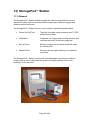
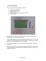
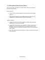
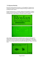
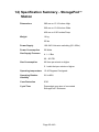
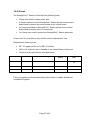
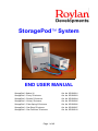
StoragePod System END USER MANUAL StoragePod Station V2 Cat. No. SPOD0001 StoragePod “Purley” Enclosure Cat. No. SPOD0003 StoragePod “Dundee” Enclosure Cat. No. SPOD0004 StoragePod “Ockley” Enclosure Cat. No. SPOD0005 StoragePod “Palm Springs” Enclosure Cat. No. SPOD0006 StoragePod “San Diego” Enclosure Cat. No. SPOD0007 StoragePod “San Francisco” Enclosure Cat. No. SPOD0010 Page 1 of 40 Operators Manual Contents 1) 2) 3) 4) 5) Introduction & Product Overview ..................................................................3 Heath and Safety Notes .................................................................................6 WARNING STATEMENTS ............................................................................7 Caution Notes ..................................................................................................7 Before Using Your StoragePod System ...................................................8 5.1) Main Packaging Case – StoragePod Station..........................................8 5.2) StoragePod Enclosure Packaging ............................................................8 6) Operating Environment ..................................................................................9 7) Gas Supply Specification ............................................................................ 10 8) Connecting the Inert Gas Supply............................................................... 11 8.1) UK, Europe and Asia ............................................................................... 11 9) Connecting the Power ................................................................................. 12 10) Connecting the Flushing Lines ............................................................... 13 11) Operating Procedures - StoragePod Enclosures............................. 14 11.1) Lid & Latch System .............................................................................. 14 11.2) Releasing the Enclosure Lid/Door ..................................................... 15 11.3) Re-Fitting the Enclosure Lid ............................................................... 17 11.4) Quick Release Hose Fittings .............................................................. 19 11.5) Engaging the Quick Release Hose Fittings ..................................... 20 11.6) Disengaging the Quick Release Hose Fittings ................................ 21 12) StoragePod Enclosure Designs ............................................................. 22 13) StoragePod Station............................................................................... 23 11.1) General .................................................................................................. 23 11.2) User Interface ....................................................................................... 24 11.3) StoragePod Station System States ................................................... 25 11.4) System Start-Up ................................................................................... 26 11.5) System Calibration ............................................................................... 28 11.6) Flush Set-up and Threshold Setting .................................................. 30 11.7) The Gas Flushing Procedure – System Operation......................... 32 14) Specification Summary - StoragePod Station .................................. 35 15) System Maintenance – StoragePod Station..................................... 36 15.1) Safety ..................................................................................................... 36 15.2) General Maintenance .......................................................................... 36 15.3) Mains Lead, Gas Supply Hose and Flushing Lines ........................ 36 15.4) Fuses...................................................................................................... 37 15.5) Gas Sensor Maintenance and Replacement................................... 38 16) System Maintenance – StoragePod Enclosures.............................. 39 Page 2 of 40 1) Introduction & Product Overview 1.1) Compound Storage A research operation’s small molecule compound collection is often its most precious asset. Compounds are the fundamental ingredients required for pharmaceuticals research assays. Pharmaceuticals research would grind to a halt without them. Many compounds often require complicated and lengthy chemistry to be created, or are derived from natural products making them difficult and sometimes even impossible to replace. Accordingly, maintaining compounds is of great importance within the research environment. Compound degradation will invalidate the screening process, resulting in wasted research effort and expense. More importantly, damaged compound collections may present the possibility that a potential lead compound could be missed during the screening process. Compounds can be damaged in a variety of ways: • Due to reactions caused by the presence of ultra violet light • Due to reactions caused by the oxygen present in the free air we are currently breathing • Due to moisture absorption of Dimethyl Sulfoxide (DMSO), a highly hydrophilic agent that is universally used to solubilise compounds into a liquid form. In particular this moisture absorption will lead to: • • depression of the DMSO freezing temperature • ice crystal formation when freezing • crushing of compounds • compounds falling out of solution. Due to freeze-thaw cycles. Many research operations freeze their compounds in an effort to stop moisture absorption and possible chemical (oxygen) reactions. The presence of moisture (as described above), in combination with free thaw cycles can lead to the most significant damage. Page 3 of 40 1.2) The StoragePod System The StoragePod System is a modular storage solution, designed to address the various mechanisms which result in compound degradation. The StoragePod System consists of a StoragePod Station desktop instrument and as many StoragePod Enclosures as the End User requires for their storage application. SBS format Labware (plates, racks of tubes, etc.) containing small molecule compounds may be placed into the StoragePod Enclosures, which can be closed with a hermetic (gas tight) seal. An enclosure may then be connected to the StoragePod Station, which will flush the environment within the enclosure using inert gas (nitrogen or argon) to expel the oxygen and moisture that is present. The gas flushing procedure is fully automatic and may be instigated at the touch of a button. The final conditioning of each flushed enclosure is achieved by flushing until a User defined residual oxygen content is achieved within the enclosure. The system default is a residual oxygen content of 2% Once the flushing procedure has been completed the enclosure may be disconnected from the StoragePod Station and left for many months, with virtually no change in the inert gas storage environment. As part of the flushing processes the StoragePod Enclosures are sealed with a positive pressure, meaning that should any leakage occur only inert gas will leak out – no moist air will leak in. Page 4 of 40 In summary the StoragePod System allows varied quantities of material to be cheaply and efficiently stored, free of moisture, oxygen and light – removing the leading causes of compound degradation. The StoragePod System is ideal for the following applications: • the primary storage system for a small research operation • a satellite storage system for a large sized research operation • a low cost, long term storage system • a delivery system for compounds being shipped within or between research sites – no more boxes of dry ice! Page 5 of 40 2) Heath and Safety Notes It is important to ensure that the StoragePod System is installed and operated in accordance with all applicable Health and Safety requirements. It is the Users responsibility to ensure that all relevant Heath and Safety Regulations are identified and complied with. Failure to do so may result in damage to equipment, damage to property and personal injury. In particular, the User should study the contents of this operator’s manual carefully, before handling and/or operating this equipment in any way. Under no circumstance will the manufacturer of this equipment be liable for any incidental, consequential or special damages of any kind whatsoever, including but not limited to personal injury, death, damage to buildings, loss of turnover and business and business interruption. WARNING SYMBOLS Used in Accordance with IEC 417 WARNING! (Please Refer to Accompanying Documentation) Page 6 of 40 3) WARNING STATEMENTS WARNING: Only operate your StoragePod Station within well airconditioned spaces. The StoragePod System vents inert gas during the gas flushing procedure. Whilst the volume of vented gas is minimal, air conditioning is required to remove this vented gas and prevent a build up of the inert gas level within the surrounding free air WARNING: Do not operate this instrument in an atmosphere containing explosive gasses WARNING: Only the supplied, approved mains cord set should be used with this instrument WARNING: If used, power extension leads MUST be earthed WARNING: Do not position the StoragePod Station so that it is difficult to disconnect the mains plug or appliance coupler WARNING: Protection of the End User may be impaired if the StoragePod system is used in a manner not specified by Roylan Developments Ltd. 4) Caution Notes Roylan Developments Limited accepts no liability resulting from the misuse of this equipment. Page 7 of 40 5) Before Using Your StoragePod System During the unpacking process, please carefully inspect your StoragePod Station and Enclosures for any damage that may have occurred during shipping. Do not use the StoragePod Station or any Enclosures that are identified as having been damaged in transit. 5.1) Main Packaging Case – StoragePod Station Please carefully store your StoragePod Station packaging. In the event the unit needs to be shipped in the future, the packaging will be required to ship the unit in the correct manner. Please check that all of the components provided in the packing list below are present: • • • • • • • StoragePod Station Flushing Lines, 1 pair (a blue line and a red line) Instruction Manual Mains lead 1 meter length of 10mm supply tubing 2 meter length of 10mm supply tubing 10mm to ¼ inch supply tubing converter (for End Users based in the USA and Canada) In the event that the StoragePod Station is identified as being damaged during shipping, or item(s) are missing from the packing list, please contact you local Roylan Developments Dealer or Roylan Developments in the UK for assistance. Please refer to our web site www.spod-technology.com for the most current set of contact details Roylan Developments will NOT ACCEPT RESPONSIBILITY for any damage incurred during return shipping unless the StoragePod Station is returned in its original packaging. 5.2) StoragePod Enclosure Packaging StoragePod Enclosures are supplied in a fully assembled state and so there is no packing list for these items. In the event the StoragePod Enclosures are being used for shipping between sites, the supplied cardboard packaging cases may be used to protect each enclosure. Replacement StoragePod packaging cases may be purchased separately. Page 8 of 40 6) Operating Environment The StoragePod Station should be operated in the following environment: Temperature: 15-40 Degrees Centigrade Facility: A clean laboratory space with a footprint of at least 18 square meters or 200 square feet Environmental: Air-conditioned with HVAC providing a minimum turnover of three volumes of room air per hour Placement: On a laboratory bench capable of carrying 50Kg or 120lbs in weight and have sufficient space around it for at least one enclosure to be placed and connected via the 1 meter long flushing lines. NOTE: longer flushing lines are available for applications weher StoragePod enclosures are placed greater than 1m away from the StoragePod Station. Please contact Roylan Developments for further details. Page 9 of 40 7) Gas Supply Specification The inert gas supply to the StoragePod Station should supply either argon or more commonly nitrogen. The inert gas supply should conform to the following specification: Supply pressure (bar): 4.1 Supply pressure (PSI): 60 Supply flow rate (litres/minute): 60 or higher Supply flow rate (cubic feet/minute): 2.1 or higher Ideally the gas should be supplied from a gas cylinder or dewar (liquid nitrogen boil-off system) fitted with a suitable regulator. This will provide inert gas at a high flow rate and virtually 100% purity. In the event a nitrogen or argon generator is being used to supply the system with inert gas, a dryer/filter assembly should be implemented between the generator and the StoragePod Station. In this case the out-put gas being supplied to the system it MUST be clean, oil free and at least 99.5% pure. Some in house inert gas supplies (particularly those fed from a nitrogen generator rather than a liquid nitrogen boil-off system) are not completely dry. This is normally due to either: • The use of a nitrogen generator with an insufficient drying stage • Extended lengths of in-house piping that is moisture permeable • A long length of supply tubing has been left connected to a closed supply tap, where the residual gas within the tubing has drawn in significant moisture (NOTE – INERT GAS SHOULD BE PURGED THROUGH SUCH SUPPLY TUBING BEFORE CONNECTING IT TO THE STORAGEPOD STATION) The StoragePod Station will alert the End User in the event that background moisture is detected. The option will be given to re-try the calibration or select the Page 10 of 40 8) Connecting the Inert Gas Supply 8.1) UK, Europe and Asia The StoragePod Station is fitted with a 10mm push in connector. Please use the supplied 10mm push fit plastic tubing to plug into this connector as pictured below: End Users based in the USA or Canada should use the supplied 10mm to ¼ inch tube converter. PLEASE NOTE – INERT GAS SHOULD BE VENTED FROM THE SUPPLY THROUGH THE SUPPLY TUBING FOR AT LEAST 10 SECONDS, PRIOR TO FITTING THE TUBING TO THE STORAGEPOD STATION. THIS IS TO PURGE ANY MOISTURE THAT HAS BEEN ABSORBED INTO THE OPEN SUPPLY HOSE. Page 11 of 40 9) Connecting the Power The StoragePod Station features a standard IEC power inlet and auto switching power supply unit. Accordingly there are no switches to be set for different supply voltages – the unit will automatically detect and configure itself for each given supply voltage. Please connect the supplied mains lead into the IEC power inlet at the rear of the StoragePod Station. Now connect the plug on the mains lead into a mains power socket. Please press the red power button on the display besel of the StoragePod Station, positioned at the bottom right hand corner of the liquid crystal display. The liquid crystal display should illuminate and present a start up screen. Please press the red power button again to turn the StoragePod Station off. Page 12 of 40 10) Connecting the Flushing Lines The StoragePod Station is supplied with a pair of flushing lines, which are used to connect StoragePod Enclosures to the StoragePod Station for the flushing process. The lines are pictured below. Separate red and blue lines are present with identical fitting at either end. The red line features valved female fittings and the blue line features unvalved female fittings. It is important that the lines are connected to the StoragePod Station in the correct orientation. The blue line should be connected to the left male fitting and the red line should be connected to the right male fitting. For clarity the text next to each fitting is colour coded. NOTE: It does not matter which ends of the flushing lines are attached to the StoragePod Station as the fittings at either end of each line are the same. Page 13 of 40 11) Operating Procedures - StoragePod Enclosures 11.1) Lid & Latch System StoragePod Enclosures are designed with lids or hinged doors that seal with a number of spring loaded latches The latches are sprung to ensure an even clamping force around the sealing interface between the enclosure lid and main body. In particular the latches feature a locking system to prevent them from springing open if knocked accidentally. The switch for the locking system is presented in the images below. Please take a moment to inspect an enclosure latch and try pushing the switch inwards and downwards to unlock the latch. Place fingers under the latch lever and thumb on the latch switch Depress the latch switch with the thumb Whilst depressing the latch switch, swing the latch upwards with fingers Page 14 of 40 11.2) Releasing the Enclosure Lid/Door To remove the lid from a StoragePod Enclosure main body please perform the following procedure: 1. Position the Enclosure on a lab bench oriented; as shown in the picture below: 2. With both left and right hands, simultaneously grasp the left and right hand front latches respectively; as shown in the picture below: 3. Depress the locking switches with your thumbs and lift the latches upwards and o utwards; as shown in the pictures below: 4. Repeat procedures 2. and 3. with the second set of latches at the other end of the enclosure. Page 15 of 40 5. Ensure that the latches are free of their retaining strikes on the lid, as shown in the picture below: 6. Lift the lid free of the enclosure main body by its handles. Page 16 of 40 11.3) Re-Fitting the Enclosure Lid To re-fit the lid to a StoragePod Enclosure main body please perform the following procedure: 1. Position the Enclosure main body o n a lab bench oriented with the latches to the sides; as shown in the picture below: 2. Pick up the enclosure lid by the handles and position it over the enclosure main body; as shown in the picture below: Page 17 of 40 3. With both left and right hands, simultaneously grasp the left and right hand front latches respectively and engage them with the corresponding retaining strikes on the lid; as shown in the picture below: 4. With both left and right hands, simultaneously grasp the left and right hand front latches respectively and push them downwards until they lock; as shown in the picture below: 5. Repeat procedures 3. and 4. with the second set of latches at the other end of the enclosure. Page 18 of 40 11.4) Quick Release Hose Fittings Each StoragePod Enclosure is fitted with a pair of female quick release hose fittings. These fittings are used to allow purge gas to be flushed into and out of an enclosure. The fittings are positioned on opposite enclosure sides to provide effective and rapid gas mixing. The StoragePod Station features a pair of flushing lines, at the ends of which male quick release fittings are present. As part of the gas flushing cycle for conditioning an enclosure, the User is required to engage and subsequently disengage the male connectors on the StoragePod Station flushing lines, with the female connectors fitted to the enclosure main body. Page 19 of 40 11.5) Engaging the Quick Release Hose Fittings To engage a quick release hose fitting, please perform the following procedure: 1. Firmly grasp a male quick release fitting at the end of a flushing line and align the fitting with a one of the Female fittings in the enclosure main body; as shown in the picture below: 2. Engage the fittings by pushing them together until a ‘click’ is heard. 3. In the event that the fittings will not engage, it may be that the locking mechanism on female fitting (mounted to the enclosure main body) has been inadvertently moved to the locked position. Should this be the case please depress the fitting release switch; as shown in the picture below: Page 20 of 40 11.6) Disengaging the Quick Release Hose Fittings To disengage a quick release hose fitting, please perform the following procedure: 1. Firmly grasp a male quick release fitting at the end of a flushing line and depress the locking switch on the connected female fitting; as shown in the picture below: 2. Pull the male fitting away from the enclosure body; as shown in the picture below: Page 21 of 40 12) StoragePod Enclosure Designs At the time of writing this manual the following StoragePod Enclosure designs are available: Name Cat. No Capacities Purley SPOD0003 • • • • 36 x shallow well microplates 6 x deep well blocks 12 x 0.75ml tube racks 6 x 1.4ml tube racks Dundee SPOD0004 • • • • 54 x shallow well microplates 12 x deep well blocks 18 x 0.75ml tube racks 12 x 1.4ml tube racks Short Dundee SPOD0011 • • • • 36 x shallow well microplates 8 x deep well blocks 12 x 0.75ml tube racks 8 x 1.4ml tube racks Ockley SPOD0005 • • • • 54 x shallow well microplates 12 x deep well blocks 18 x 0.75ml tube racks 12 x 1.4ml tube racks Palm Springs SPOD0006 • • • • 80 x shallow well microplates 18 x deep well blocks 22 x 0.75ml tube racks 18 x 1.4ml tube racks San Diego SPOD0007 • • • • 240 x shallow well microplates 54 x deep well blocks 66 x 0.75ml tube racks 54 x 1.4ml tube racks San Francisco SPOD0010 • • • • • • 252 x shallow well microplates (with loose lids) 288 x shallow well microplates (with loose lids) 72 x deep well blocks 144 x 0.5ml tube racks 72 x 0.75ml tube racks 72 x 1.4ml tube racks Please refer to the Roylan Developments StoragePod web-site www.spod-technology.com for further details and the latest StoragePod Enclosure developments. Page 22 of 40 13) StoragePod Station 11.1) General The StoragePod Station software guides the User through all the functions required to safely flush an enclosure with nitrogen gas to defined oxygen and moisture backround levels. The StoragePod Station has four main modes of operation/system states: • Power On Self Test Tests the inert gas supply pressure and 7.5 PSI safety blow off valve • Calibration Calibrates the oxygen and humidity sensors and confirms the purity of the inert purge gas • Set-up Flush Sets the oxygen and moisture threshold levels for a flush cycle • Repeat Flush Performs the inert gas flushing of an attached enclosure The StoragePod Station monitors all critical hardware and set-up conditions. In the event an error is detected the system will display details of the error enabling it to be resolved. Page 23 of 40 11.2) User Interface The user interface (pictured below) consists of: • • • • • a red power on/off button four black control butto ns a red power LED a tricolour red, green and orange status LED an LCD display The StoragePod Station also features a piezoelectric buzzer to provide audible alerts to the User during operation. A momentary press of the red power button will power the unit on. If the unit is already on, pressing and holding the red button for longer than 2 seconds will turn the unit off, regardless of its current state. The four black control buttons are dynamically labelled on the LCD during system use. Step by step instructions are augmented with the front panel tri-colour status LED and an internal piezoelectric buzzer that informs the user of the unit’s operating conditions. Page 24 of 40 11.3) StoragePod Station System States The tri-colour status LED has three colour states, defining the following individual system states: System start-up: • Green LED illuminates for approx 3 seconds while system power stabilises • After System Power UP, Green LED illuminates for 500mS then Orange LED for 500mS and then Red LED fo r 500mS System operation: • Green LED indicates that the StoragePod Station has passed an internal test or set point successfully • Orange LED indicates that the StoragePod Station requires user attention, such as Increasing the inert gas supply pressure or the StoragePod Station is making internal adjustments, such as adjusting gain settings • Red LED indicates that the StoragePod Station has failed an internal test or set point Page 25 of 40 11.4) System Start-Up During the initial seconds of power up, the StoragePod Station User Interface will display the Roylan Developments logo and details of the installed firmware version. Roylan Developments is constantly updating the StoragePod Station firmware with improvements and new features. Please contact Roylan Developments to obtain details of the latest firmware releases. After displaying details of the installed firmware version the StoragePod Station will prompt the End User to disconnect the flushing hoses from an enclosure if one is connected and then press the NEXT button. If the NEXT button is not pressed within two minutes the StoragePod Station will power down. Page 26 of 40 The StoragePod Station will then perform a rapid inert gas, static supply pressure check. If the measured pressure is within acceptable limits the user is prompted that the inert gas line pressure is good. The StoragePod Station will now perform a secondary pressure (and gas flow rate) check with inert gas flowing through the system, to ensure that the minimum required inert gas supply pressure is available under load. This test is conducted by passing inert gas through the StoragePod Station’s safety blow-off valve, thus also providing a test of this valve to ensure it is functioning within it pre-defined limits. In the event the gas supply pressure is too low the StoragePod station will notify the User via the user interface and with an audible warning. In this event the system should be turned off using the red power button and the supply pressure should be increased. After checking the available inert gas supply static pressure and pressure under load the StoragePod Station will perform an automatic calibration procedure. Page 27 of 40 11.5) System Calibration After the start-up tests the StoragePod Station will perform a calibration cycle for the onboard oxygen and humidity sensors. In particular the oxygen sensor requires periodic calibration, due to the chemicals within it breaking down over time. The StoragePod Station will calibrate in accordance with the following schedule: • Upon initial start-up • Once every two weeks • Upon start-up where mains power to the StoragePod Station has been disconnected and re-connected (i.e. because the StoragePod Station has been moved within a laboratory) • When the End User forces a calibration cycle within the StoragePod Station User Interface. This calibration procedure may take up to 2 minutes. In the event the initial calibration cycle was not 100% successful the StoragePod Station will perform a secondary calibration. Page 28 of 40 Some in house inert gas supplies (particularly those fed from a nitrogen generator rather than a liquid nitrogen boil-off system) are not completely dry. This is normally due to either: • The use of a nitrogen generator with an insufficient drying stage • Extended lengths of in-house piping that is moisture permeable • A long length of supply tubing has been left connected to a closed supply tap, where the residual gas within the tubing has drawn in significant moisture (NOTE – INERT GAS SHOULD BE PURGED THROUGH SUCH SUPPLY TUBING BEFORE CONNECTING IT TO THE STORAGEPOD STATION) The StoragePod Station will alert the End User in the event that background moisture is detected within the inert as supply. The option will be given to retry the calibration or set an ‘effective’ zero humidity level at the detected background humidity level. Page 29 of 40 11.6) Flush Set-up and Threshold Setting Once calibrated the StoragePod Station will present the SETUP FLUSH MODE menu. This menu will allow the End User to purge enclosures with the following options: • • • Purge to a defined oxygen threshold Purge to a defined humidity threshold Purge to COMBINED oxygen and humidity thresholds The instructions provided in this End User manual will now assume that option 3, to flush with both oxygen and humidity thresholds will be selected. The StoragePod Station User Interface will now prompt the User to select a humidity threshold level at which the StoragePod station will terminate a flush cycle. This threshold level represents the percentage level of humidity left remaining within the connected enclosure. The typical percentage level of humidity in free air-conditioned laboratory air is approximately 45%-50% and the factory default threshold setting is 1%, providing an approximate 50-fold reduction in moisture content. If desired, the humidity threshold level can be increased or decreased in 0.5% increments down to 0.1%. Page 30 of 40 The StoragePod Station User Interface will now prompt the User to select an oxygen threshold level at which the StoragePod station will terminate a flush cycle. This threshold level represents the percentage level of oxygen left remaining within the connected enclosure. The percentage level of oxygen in free air is approximately 21% and the factory default threshold setting is 1%, providing an approximate 20-fold reduction in oxygen content. If desired, the oxygen threshold level can be increased or decreased in 0.5% increments down to 0.1%. The StoragePod Station will save the selected humidity and oxygen threshold levels, allowing the User to implement them in successive flush cycles. A menu option is also available at the end of each flush cycle, allowing the User to return to the StoragePod station’s main menu where the threshold setting can be changed. Page 31 of 40 11.7) The Gas Flushing Procedure – System Operation Once the threshold level has been set the StoragePod Station is ready for use. The User will be again prompted to ensure the flush hoses have been disconnected from the e nclosure. The StoragePod Station will then clear the flush lines of any residual inert gas. The User is now asked to connect both the inlet and outlet hoses to the Enclosure. Upon depressing the NEXT button the StoragePod Station flushes the connected enclosure with inert gas. An on screen display can be seen detailing the progress of the flush cycle, by presenting the decreasing humidity and oxygen content within the enclosure in real time. Page 32 of 40 The StoragePod Station will continue purging until both threshold levels have been reached. Upon reaching the threshold setting the StoragePod Station completes the flush cycle by setting the positive pressure level within the enclosure. Once the positive pressure level has been set the User will be prompted to disconnect both the inlet and outlet hoses from the enclosure. Page 33 of 40 The StoragePod Station will now present the User with the option to perform another purge cycle with the same threshold settings, or instead access the StoragePod Station’s main menu. The main menu will allow the End User to: 1) Repeat a StoragePod enclosure flush cycle with the previous settings 2) Setup a new threshold value 3) Calibrate the StoragePod Station’s oxygen sensor Page 34 of 40 14) Specification Summary - StoragePod Station Dimensions 385 mm or 15.16 inches High 260 mm or 10.24 inches Wide 430 mm or i6.93 inches Deep Weight 16 kg 25 lbs Power Supply 100-240 Volts auto switching (50 - 60Hz) Power Consumption 50 Watts Gas Supply Pressure 4.1 – 6 Bar 60 – 85 PSI Gas Consumption 60 litres per minute or higher 2.1 cubic feet per minute or higher Operating temperature 15-40 Degrees Centigrade Operating Relative Humidity 5% to 85% Case Protection IP20 Cycle Time Dependant upon size of connected StoragePod Enclosure Page 35 of 40 15) System Maintenance – StoragePod Station 15.1) Safety Please disconnect the mains power lead from the StoragePod Station before performing any maintenance operation that requires the StoragePod Station case to be opened/removed. Maintenance should only be performed by authorised and suitably trained/qualified personnel. 15.2) General Maintenance The StoragePod Station has been designed to feature minimal maintenance requirements. In particular the StoragePod Station features no moving parts that require periodic mechanical adjustment or that might wear out with use. Indeed the only moving parts present in the system are a small number of solenoid driven gas valves, which are rated to tens of millions of cycles. Maintenance is typically restricted to cleaning the exterior of the StoragePod Station with a damp cotton cloth, followed by the light application of some furniture polish. 15.3) Mains Lead, Gas Supply Hose and Flushing Lines Please periodically inspect the mains lead, gas supply hose feeding inert gas to the StoragePod Station and the flushing lines. Please visually inspect these items and if there are signs of wear or material fatigue, please replace them immediately. Replacement flushing lines are available from Roylan Developments as catalogue number SPOD0002. Replacement gas-supply hose and power leads should to conform to the known applicable safety standards pertinent to the region the StoragePod system is installed into. It is the E nd Users responsibility to ensure that these standards are complied with. Page 36 of 40 15.4) Fuses The StoragePod Station is fitted with the following fuses: • 13amp fuse fitted in mains power lead • 6.3amp fuse fitted on the StoragePod Station printed circuit control board used to protect the entire printed circuit control board • 5x 1amp fuses fitted on StoragePod Station printed circuit control board used to protect various components • 1x 0.2amp fuse used to protect the StoragePod Station gas pump In the event of a fuse failure, only refit the correct replacement fuse. Replacement fuses must be: • IEC 127 approved for use in EEC Countries • CSA or UL listed for use in Canada or the United States of America • Conform to the specification provided below Manufacturer Part No. IEC60127 Rating Current Rating (Amps) Designation on PCB Littlefuse 218001 F1AL250V 1 F2, F3, F4, F5, F6 Litttefuse 216.200 F200mAL250V 0.2 F10 Schurter 0034.1524 F6.3AL250V 6.3 F1 Fitting of replacement fuses should be performed by a suitably skilled and competent Engineer. Page 37 of 40 15.5) Gas Sensor Maintenance and Replacement The StoragePod Station features a gas sensor. This sensor has a nominal life expectancy of 2 years, due to the chemicals within it breaking down over time. The StoragePod Station will self compensate for the sensor degradation to ensure accurate gas analysis. However a point will eventually be reached where the sensor will need to be replaced. For convenience the StoragePod Station will automatically detect when the sensor requires replacement, well in advance of the sensor wearing out. Replacement of the senor is a simple task. This may be performed: • By returning your StoragePod Station to Roylan Developments in the UK • By purchasing a replacement sensor kit – catalogue number SPOD0008. This kit includes the sensor, tools and instructions required for the sensor replacement. Sensor replacement is a simple task requiring only removal of the StoragePod Station cover to access the sensor. A suitably skilled and competent Engineer should perform the replacement referring to the sensor replacement manual supplied as part of the sensor replacement kit. Please contact your local Roylan Developments Dealer or Roylan Developments in the UK to arrange for a replacement sensor kit to be dispatched to you, or to book your StoragePod Station in for sensor replacement at Roylan Developments in the UK. Page 38 of 40 16) System Maintenance – StoragePod Enclosures StoragePod Enclosures are designed with minimal maintenance requirements and so only very simple and infrequent maintenance checks/activities are required. Accordingly, to ensure that enclosures remain in a serviceable state, please periodically perform the following simple maintenance checks and activities: • Visually check the sealing material in the enclosure lid for any damage or heavy wear • Check that the movement of the latches is free and that the locking mechanism functions correctly • For enclosures with a stainless steel finish, please wipe the enclosure exterior with fine machine oil or baby oil applied with a fine cotton cloth • For enclosures with a painted finish, please clean the enclosure exterior with a damp cotton cloth, followed by the light application of some furniture or automotive polish Page 39 of 40 Roylan Developments Ltd. 79 Cannon Grove Fetcham Leatherhead Surrey KT22 9LP UK Tel: +44 (0) 1372 377 754 Fax: +44 (0) 1372 388 282 Web: www.spod-technology.com Page 40 of 40