1
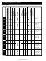
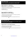
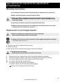
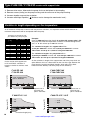
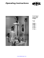
Operating Instructions
Centrifugal
Immersion
Pumps
Type
F
F
F
F
F
F
www.castlepumps.com
620
640
700
706
716
726
...
...
...
...
...
...
2
www.castlepumps.com
Table of Contents
EC-Declaration of Conformity
Page
2
FLUX Centrifugal Immersion Pumps
- Pump types
- Temperature limitations
- Type codes
4
5
5
Safety instructions
Storage
Use in hazardous areas
6
6
6
Mounting instructions
Cleaning
Repair
7
7
7
Centrifugal Immersion Pump, version with support tube, with open conical impeller
Type F 620 S-15, F 620 S-30
Type F 640 PP-15, F 640 PP-30
8
8
Vertical Centrifugal Immersion Pump, version with support tube, with closed centrifugal impeller
Type F 640 PP-15Z, F 640 PP-30Z
Type F 640 PP-185,F 640 PVDF-185
8
Centrifugal Pump for horizontal use
Type F 620 S-30 TR, F 640 PP-30 TR, F 640 PP-230 TR
9
Centrifugal Immersion Pump, version with support tube
Type F 700 PP-230, F 700 PVDF-230
10
Variation in length depending on the temperature
10
Centrifugal Immersion Pump, version with support tube
Type F 706 PP1-135, F 706 PP1-185, F 706 PP1-230, F 706 PP1-350
11
Centrifugal Immersion Pump, version with support tube
no bearings nor seals in contact with the liquid
Type F 716 PP1-115, F 716 PP1-135, F 716 PP1-185, F 716 PP1-230,
Type F 716 PVDF1-115, F 716 PVDF1-135, F 716 PVDF1-185, F 716 PVDF1-230
11
Centrifugal Immersion Pump, version with support bars
no bearings nor seals in contact with the liquid
Type F 716 PP2-115, F 716 PP2-135, F 716 PP2-185, F 716 PP2-230,
Type F 716 PVDF2-115, F 716 PVDF2-135, F 716 PVDF2-185, F 716 PVDF2-230
11
Centrifugal Immersion Pump, version with support bars
no bearings nor seals in contact with the liquid
Type F 726 PP2-115, F 726 PP2-135, F 726 PP2-185, F 726 PP2-230,
Type F 726 PVDF2-115, F 726 PVDF2-135, F 726 PVDF2-185, F 726 PVDF2-230
11
3
www.castlepumps.com
Centrifugal Immersion Pumps
Pump types :
F 706 X
X
0,37 kW to 5,5 kW
X
0,37 kW to 5,5 kW
X
X
2850 rpm
X
X
No
X
No
(operating time exceeding 4 h/day)
X
continuous operation
suitable for dry operation
Pump Type
mechanical seal
in contact with the liquid
free-flying shaft
shaft bearing
lubricated by the liquid
shaft bearing
lubricated permanently
0,75 kW to 4,0 kW kW-rating
X
F 716
F 726
nominal speed
2850 rpm
X
X
1450 / 2850 rpm
X
0,75 kW to 4,0 kW
X
X
0,75 kW to 4,0 kW
F 700 X
X
0,37 kW to 5,5 kW
X
2850 rpm
F 640 X
X
1450 /
2850 rpm
X
Type of bearing
1450 /
2850 rpm
F 620 X
Drive Motor
consisiting of an inner
and outer tube
standard-dimensioned
three-phase motor
integral three-phase motor
with extended shaft
standard three-phase motor
with pedestal
version with support bars
Design
version with support tube
Type
No
No
F 620 S - 15
F 620 S - 30
F 620 S - 30 TR
F 640 PP - 15
F 640 PP - 15 Z
F 640 PP - 30
F 640 PP - 30 Z
F 640 PP - 30 TR
F 640 PP/PVDF - 185
F 640 PP - 230 TR
X
X
No
No
No
F 700 PP - 230
F 700 PVDF - 230
Yes
F 706 PP1 - 135
F 706 PP1 - 185
F 706 PP1 - 230
F 706 PP1 - 350
X
Yes
Yes
X
Yes
Yes
X
Yes
Yes
4
www.castlepumps.com
F 716 PP1 - 115
F 716 PP1 - 135
F 716 PP1 - 185
F 716 PP1 - 230
F 716 PP2 - 115
F 716 PVDF2 - 115
F 716 PP2 - 135
F 716 PVDF2 -135
F 716 PP2 - 185
F 716 PVDF2 - 185
F 716 PP2 - 230
F 716 PVDF2 - 230
F 726 PP2 - 115
F 726 PVDF2 - 115
F 726 PP2 - 135
F 726 PVDF2 - 135
F 726 PP2 - 185
F 726 PVDF2 - 185
F 726 PP2 - 230
F 726 PVDF2 - 230
Centrifugal Immersion Pumps
Temperature limitations :
Type
Operating temperature
material
version with support tube version with support bars
F 620
S (316 Ti)
0°C up to max. +100°C
-
F 640 - 15 /30 /15Z /30Z
PP
0°C up to max. +50°C
-
PP
0°C up to max. +60°C
PVDF
0°C up to max. +80°C
PP / PVDF
0°C up to max. +60°C
-
PP
0°C up to max. +60°C
-
PP
0°C up to max. +60°C
F 640 - 185
F 700
F 706
F 716
F 726
0°C up to max. +80°C
PVDF
-
0°C up to max. +100°C
PP
-
0°C up to max. +80°C
PVDF
-
0°C up to max. +100°C
Type code :
F 620
horizontal version
pump housing size
closed centrifugal impeller
open conical impeller
version with support tube
version with support bars
Material
S = stainless steel 316 Ti
PP = Polypropylene
PVDF=Polyvinylidenfluoride
Type
for example:
F 620 S-15
F 640 PP-15Z
F 640 PP-30 TR
F 640 PVDF-185
F 716 PP1-115
F 726 PVDF2-230
15
S
30
TR
15
15Z
PP
30
F 640
TR
30Z
185
PP
F 700
F 706
F 716
PP / PVDF
PP
PP / PVDF
1
2
F 726
PP / PVDF
-
depending on the requested delivery rate and head
PP / PVDF
230 TR
230
135
185
230
350
115
135
185
230
115
135
185
230
5
www.castlepumps.com
Safety instructions
l When exceeding the temperature limitations, the pump will be damaged.
l The pumps are not allowed for use with flammable liquids ( ZONE 0 ).
l Only use the pump for its intended purpose.
l Only use the pump in connection with suitable pipelines, fittings and/or flexible hoses.
l Regularly check the pipelines, fittings, flexible hoses and power supply cables
to ensure safe operation.
l Keep solvents away from the power supply cable.
l The pump should not be exposed to the weather.
l Comply with all relevant safety instructions. Wear appropriate protective clothing.
( Face shield, protective cloves, etc. )
l On three-phase motors comply with the safety instructions contained with
the terminal box.
l Installation, maintenance and repairs to three-phase motors should only
be carried out by suitably qualified personnel.
l Only use three-phase motors with a starter including and overload cut-out.
l Make sure that the supply voltage corresponds to the voltage indicated
on the name plate.
l Comply with technical requirements of local power supply companies.
l Check direction of rotation of the three-phase motor.
In case of portable use, check the conformity of phases at each socket
to guarantee always the same direction of rotation.
( Direction of rotation according to the arrow on the bearing flange ).
l Before inserting the electrical plug into the socket, ensure that the starter is set to "0" (Stop).
Storage
l Always store the pump in a vertical position.
l Temperature during storage should not drop below -10°C.
l Before starting operation, warm up the pump to operating temperature.
Use in hazardous areas
Only use three-phase motors which are approved for use in hazardous areas
( ZONE 1 ).
l Explosion-proof three-phase motors 0,37 to 5,5 kW, 1450 or 2850 rpm.
Observe Test Certificate or Certificate of Conformity.
The installation and operation must comply with the relevant Health & Safety
Regulations. ( In the Federal Republic of Germany these are "TRbF" and
"BG Chemie" ).
6
www.castlepumps.com
Mounting instructions
l When fitting the mounting flange onto the container, no tensions must be transmitted
to the pump. Only fit the pump to a stable support to ensure a vibration-free running.
l When pipelines are connected to the pump, no tensions must be transmitted
to the pump. In case of higher operating temperatures, bellow expansion joints
have to be installed into the discharge pipe.
l Avoid dry running on pump types F 620, F 640, F 700 and F 706.
On models with extension tube make sure that the motor will not be switched on,
when the level of the liquid is underneath the pump housing.
( Minimum and maximum liquid level see dimensional drawing supplied with the pump ).
l Distance to the bottom of the container should be approx. 40 - 80 mm
The distance to the bottom of the container depends on the immersion length of the
pump. Temperature variations will cause variations in pump length.
l In case of intense turbulences within the container in operating pump types
F 620, F 640 and F 700 with longer immersion lengths, support the pump at
approx. 2 m in a way that ensures that it may expand in axial direction
( Thermal elongation of the pump ).
l The site of operation should be set up in a way that leakage may not cause
any damage.
l Before untertaking any maintenance or repair to three-phase motors,
disconnect them from the mains.
l Completely drain the pump for repair.
Liquid may be retained within the cavities of the pump.
l Comply with all relevant safety instructions. Wear appropriate protective clothing.
( Face shield, protective gloves, etc. )
l Make sure that the pump is securely mounted.
Cleaning
Clean the pump by flushing an appropriate cleaning agent.
l Pump, flexible hose, pipelines and/or other fittings must be compatible
with the cleaning agent.
l Do not use flammable cleaning agents.
Repairs
l Repairs to FLUX Centrifugal Immersion Pumps should only be carried out by suitably
qualified personnel.
l Only cleaned and completely drained pumps may be returned to us for repair.
7
www.castlepumps.com
Type F 620 / F 640
version with support tube and open conical impeller
for thin to medium viscosity liquids up to 2500 mPas (cP)
Type F 620 S-15 / F 620 S-30
Replacement of conical impeller
1. Remove drive motor. Afterwards the pump shaft can be locked at the coupling.
2. Unscrew entry housing ! Left-hand thread.
3. Unscrew cap nut.
4. Remove conical impeller.
Type F 640 PP-15 / F 640 PP-30
Replacement of conical impeller
1. Remove drive motor. Afterwards the pump shaft can be locked at the coupling.
2. Unscrew entry housing ! Left-hand thread.
3. Unscrew impeller cap and the nut below.
4. Unscrew conical impeller (
Make sure not to damage the mechanical seal ).
Type F 640-15Z / -30Z
version with support tube and closed centrifugal impeller
for thin liquids up to 150 mPas (cP)
Replacement of centrifugal impeller
1. Remove drive motor. Afterwards the pump shaft can be locked at the coupling.
2. Unscrew entry housing ! Left-hand thread.
3. Unscrew impeller cap and the nut below.
4. Unscrew centrifugal impeller (
Make sure not to damage the mechanical seal ).
8
www.castlepumps.com
Type F 620 S-30 TR / F 640 PP-30 TR / F 640 PP-230 TR
for horizontal use
Mounting instructions
l Only switch on the pump with a liquid feeding line connected to the pump inlet.
l Make sure that the pump is always filled with liquid.
l Make sure that the complete contents of the container can be collected in case
of leakage. The site of operation should be set up in a way that leakage may not
cause any damage.
l Stop valves should be installed at the pump inlet and outlet.
l Bellow expansion joints have to be installed into the discharge line of the pump
( Compensation of: temperature, pressure ...).
Replacement of centrifugal impeller
l Before untertaking any maintenance or repair to the pump,
disconnect three-phase motor from the mains.
l Comply with all relevant safety instructions. Wear appropriate protective clothing.
( Face shield, protective gloves, etc. )
1. Close the stop valves at the pump inlet and outlet.
2. Remove the pump.
3. Mark the stop valves and secure them against unintentional opening.
l Completely drain the pump.
Liquid may be retained within the cavities of the pump.
4.
5.
Remove drive motor. Afterwards the pump shaft can be locked at the coupling.
Remove the screws and take off the cover of the pump housing or the entry housing.
6.
6a.
On model F 640 PP-30 TR unscrew impeller cap and the nut below.
On model F 620 S-30 TR unscrew cap nut.
7.
On model F 620 S-30 TR remove conical impeller.
On model F 640 PP-230 TR unscrew centrifugal impeller.
Make sure not to damage the mechanical seal.
9
www.castlepumps.com
Type F 640-185 / F 700-230 version with support tube
1. Remove drive motor. Afterwards the pump shaft can be locked at the coupling.
2. Remove screws (circlip) on the pump housing and take off cover of the pump housing.
3. Unscrew impeller cap and the nut below.
4. Unscrew centrifugal impeller (
Make sur not to damage the mechanical seal ).
Variation in length depending on the temperature
As all materials will expand or contract with temperature variations, it is important to know which minimum or
maximum temperatures will be acceptable within the pump.
V a r ia tio n in le n g th in m m
p er 1 00 0 m m p u m p le n g th
T em p e r a tu r e
PP
PVDF
S
-4 , 0 0
-3 , 0 0
-2 , 0 0
-1 , 0 0
0,00
1,80
3,60
5,40
7,20
9,00
10,80
12,60
14,40
-4 , 4 0
-3 , 3 0
-2 , 2 0
-1 , 1 0
0,00
1,30
2,60
3,90
5,20
6,50
7,80
9,10
10,40
-0 , 6 6
-0 , 5 0
-0 , 3 3
-0 , 1 7
0,00
0,17
0,33
0,50
0,66
0,83
0,99
1,16
1,32
[°C ]
-2 0
-1 0
0
10
20
30
40
50
60
70
80
90
100
On the version with support bars
in PP and PVDF, variations in
length are similar to stainless steel
values.
Example:
Pump of 2000 mm immersion length in version with support tube in PP.
The pump must tolerate temperature variations in climate throughout the
year, i.e. 0 °C in winter up to +40°C in summer.
The variation in length of the support tube will be :
-2 mm per 1000 mm in winter and +3,6mm per 1000 mm in summer.
This means -4 mm up to +7,2 mm at a length of 2000 mm.
The variation in length of the pump shaft will be :
-0,33mm per 1000mm in winter and +0,33 mm per 1000 mm in summer.
This means -0,7 mm up to +0,7 mm at a length of 2000 mm.
As the variations in length of the support tube and of the pump shaft are
quite different, this has a direct effect on the size of the gap between the
pump housing and the centrifugal impeller, which will have a direct
influence on the delivery rate of the pump and its efficiency.
Cover of pump housing
part no. 706 45 063
Immersion length [mm]
F 640 PVDF-185
F 700 PVDF-230
Temperature [°C]
Temperature [°C]
F 640 PP-185
F 700 PP-230
Special cover on
type F 700 only,
part no. 700 41 269
... -15
... -30
... -15
Immersion length [mm]
Immersion length [mm]
Special cover on
type F 700 only,
part no. 700 60 169
F 640 PP-15 Z / -30 Z
Temperature [°C]
Temperature [°C]
F 640 PP-15 / -30
Cover of pump housing
part no. 706 65 002
... -15 Z
... -30 Z
Immersion length [mm]
10
www.castlepumps.com
... -15 Z
Type F 706 PP version with support tube
Size 135 / 185 / 230 / 350
On pump sizes 185 and 350 thoroughly clean the circlip and its groove on the pump housing.
Make sure that the circlip is properly engaged.
On pump sizes 135 and 230 screw the plastic screws with a maximum torque of 5 Nm.
1.
Remove drive motor. Afterwards the pump shaft can be locked at the coupling.
2.
Remove circlip ( plastic screws ) and take off cover of the pump housing.
3.
Unscrew impeller cap as well as the nut below.
3a. Pump size 135: Unscrew impeller body and remove impeller cover.
4.
Remove impeller.
Type F 716 / F 726 version with support tube and version with support bars
On pumps type F 716 remove motor cover.
Afterwards the pump shaft can be locked at the ventilator blade.
On pumps type F 726 remove drive motor.
Afterwards the pump shaft can be locked at the coupling.
Size 115 and 135
Torque to impeller body is max. 15 Nm.
Only screw on palstic screws until they
closely fit to the cover of the pump housing.
1. Unscrew the screws and and take off cover of the pump housing.
2. Unscrew impeller body and remove impeller cover.
2
1
Size 185
Thoroughly clean circlip and its groove on the pump housing.
Make sure that the circlip is properly engaged.
1. Remove circlip and take off cover of the pump housing.
2. Unscrew impeller cap and the nut below.
3. Remove impeller.
1
2
3
Size 230
Torque to screws on PP ( grey ) pumps is max. 5 Nm.
Torque to screws on PVDF ( white ) pumps is max. 7 Nm.
1. Unscrew the screws and take off the cover of the pump housing.
2. Unscrew impeller cap and the nut below.
3. Remove impeller.
3
2
1
11
www.castlepumps.com