1
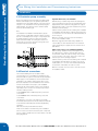
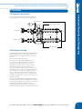
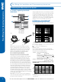
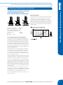
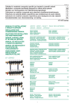
1.
Description 1.1 1.2 1.3 1.4 Components
Technical data
Pressure drops thermostatic mixer
Schematic system diagram
2
2.1 2.2 2.3 2.4 2.5 2.6 Installation
Assembly installation
Dimensional data
Circulation pump assembly
Electrical connections
Hydraulic connections
Filling and testing
3
Balancing and adjustment of the system
3.1 3.2 3.3 3.4 3.5 3.6 Double regulating lockshield adjustment
Diagrams of manifold with double regulating lockshield
Adjustment of flowmeter
Adjustment of return balancing valve
Balancing of the differential by-pass kit
Adjustment of the thermostatic mixing valve
For more information please call us on 01993 824900 or view our website at www.emmeti.co.uk
Floor Mixing Unit Operating Instructions
Floor Mixing Unit Installation and Commissioning Instructions
1
Floor Mixing Unit Installation and Commissioning Instructions
Floor Mixing Unit Operating Instructions
1. Description
The floor mixing unit is a pre-assembled manifold designed for underfloor heating systems with an integrated
thermostatic mixing valve, available from 2 to 12 ways. It has a choice of either lockshield valves or flowmeters and
is available with or without a pump. High temperature circuits (such as radiators or towel rails) can also be added as
shown using optional kits, available from 2- 12 ways, with lockshield valves.
9
6
7
4
12
13
10
8
2
9
11
3
5
5
10
1
14
1.1 Components
1. Flow bar for underfloor heating system with double
regulating lock-shields. Versions with double
regulating flowmeters are also available.
2. Flow bar for radiator system with 2 to 12-way double
regulating lockshields, using optional kits 01292316 01292336, 2-12 ways.
3. Return bar for high temperature circuits with built-in
valves ready for electrothermic heads (available
separately) using optional kits 01292316 - 01292336,
2-12 ways.
4. Return bar for underfloor heating systems with builtin valves ready for electrothermic heads (available
separately).
5. Offset mounting brackets, 210mm centres.
1.2 Technical Data
Max. temperature on
primary circuit
85 °C
Maximum operating
pressure
10 bar
Graduated scale.
Thermostatic mixing valve
min-1-2-3-4-5-max
Temperature range
adjustment, mixed water
25 °C -55 °C*
Kv mixing valve
1.8 -3.3 (min -max)
Temperature gauge range
0 -80 °C
Maximum thermal capacity
available to secondary **:
15000 W (ΔT = 10 °C)
11000 W (ΔT = 7 °C)
8500 W (ΔT = 5 °C)
Circulator pump connection
pipe unions 1”1/2
port-to-port dimension
130mm
Manifold size
1”
Primary connections
G1”
Manifold connections
M 24x19
6. 3-port thermostatic mixing valve.
7. Return balancing valve.
8. Temperature gauge, range from 0 to 80oC
9. Manual air vent ½”.
10. Drain and filling valves with rotatable connection and
safety cap.
11. Circulating pump, Grundfos UPS 25-60, optional
12. Adjustable over-temperature thermostat with wiring
box, range 30oC to 90oC with off switch position
13. Ball valve kit with or without temperature gauge pipe
unions in straight or angled pattern.
14. Internal blanking plug.
2
5
* Nominal conditions: TH = 65 °C, TC = 15 °C, PH = PC =
3 bar Qmix = 720 l/h
** Test conditions: group with Grundfos UPS 25-60 circulation pump Emmeti, connected to open manifold, Δp
secondary = 0.22 -0.25 bar
For more information please call us on 01993 824900 or view our website at www.emmeti.co.uk
Floor Mixing Unit Installation and Commissioning Instructions
1.3 Pressure drops thermostatic mixer
100,000
Knob positions
10,000
Pos. MIN - Kv = 1,9
Pos. 1 - Kv = 2,6
Pos. 2 - Kv = 3,2
Pos. 3 - Kv = 3,3
Pos. 4 - Kv = 2,9
Pos. 5 - Kv = 2,5
Pos. MAX - Kv = 1,8
p (bar)
1,000
0,100
0,010
0,001
0,000
100
1.000
10.000
Q ( l /h )
Nominal conditions: TH = 65°C; TC=15°C; PH-MIX = PC-MIX
Knob positions
Min
1
2
3
4
5
MAX
Temperature oC
-
25
33
36
43
55
-
1.4 Schematic System Diagram
C
Floor Mixing Unit Operating Instructions
1. Description
H
MIX
The numbers refer to item 1.1 on previous page.
For more information please call us on 01993 824900 or view our website at www.emmeti.co.uk
3
Floor Mixing Unit Installation and Commissioning Instructions
2.1 Assembly Installation
2.2 Dimensional Data
Floor Mixing Units can be wall-mounted using the
brackets provided with screws and plugs suitable for
the mounting surface(see Fig. A). Alternatively it can be
mounted in Emmeti cabinets suitable for a depth of not
less than 130mm (see Fig. D).
210
L
Slots for wall-mounting
or for insertion in
Metalbox enclosure
M 24x19
Fig. C
Minimum 300 mm
Fig. A
Minimum 300 mm
Floor Mixing Unit Operating Instructions
2. Installation
Fig C, no. of ways
L
2
368
3
418
4
468
5
518
6
568
7
618
8
668
9
718
10
768
11
818
12
868
355
Fig. B
For proper selection of the Metalbox enclosure, check
overall clearances (see figs. C, D, E, F, G, H, I) needed
for the Floor Mixing Unit including circulation pump and
any other accessories such as the high temperature
accessory kit, Progress kit with bypass, 1/2” terminal kit
with bypass, etc.).
Note: to install a 1/2” terminal kit c/w bypass, onto the
right hand end of the manifold set, unscrew and remove
the drain/fill valve from the end of the top rail, and the
manual air vent valve from the end of the bottom rail;
then install the kit by screwing the 1/2” M bridging
t-piece connectors onto the end of the manifold set. Reattach the drain/fill valve and manual air vent valve onto
the 1/2” F connections available on the bridging t-piece
connectors.
4
Fig. D
130*
* With Grundfos 25-60 circulation pump installed with
control box positioned as shown in Fig E.
For more information please call us on 01993 824900 or view our website at www.emmeti.co.uk
Floor Mixing Unit Installation and Commissioning Instructions
Circulation Pump Grundfos UPS 25-60
75
75
51
32
Progress ball valve kits with differential pressure bypass valve
28
102
130
1 1/2” BSPM
Fig. G
Fig. E
Progress ball valve kits
High temperature accessory kit
L
G1”
G1”
95
117
Fig. F
Model
L
2-way
130
3-way
180
4-way
230
5-way
280
6-way
330
7-way
380
8-way
430
9-way
480
10-way
530
11-way
580
12-way
630
G1”
G1”
97
120
Floor Mixing Unit Operating Instructions
2. Installation
Fig. H
1/2” terminal kit with bybass for Floor Mixing Unit
95
Fig. I
For more information please call us on 01993 824900 or view our website at www.emmeti.co.uk
5
Floor Mixing Unit Installation and Commissioning Instructions
Floor Mixing Unit Operating Instructions
2. Installation
2.3 Circulation pump assembly
On the Floor Mixing Unit group, install a circulation pump
Emmeti Shark N 6/53 (or one of equivalent performance
and dimensions), with rubber gaskets. Connect the pump
using the 1 1/2” threaded union nuts provided, using the
rubber gaskets. The outlet port of the circulation pump
must face downwards (Fig. E).
Note
For installation in a Metalbox manifold cabinet, please
ensure that the overall depth inside the cabinet is greater
than the overall depth shown in Fig. D. The pump should
be installed with the junction box at the front and the
pump outlet downwards. The mixing valve has unions
at each side ( see below) to allow the mixing valve to be
moved and the pump to be fitted.
Union Fittings
High limit thermostat, code: 28130632
Wall Mounting - Install the high limit thermostat adjacent
to the Floor Mixing Unit where the thermostat phial can be
trapped between the rubber mounting pad in the support
bracket and the surface of the flow manifold, fixing it to the
wall with screws and plugs.
Cabinet mounting - Where the Floor Mixing Unit is installed
in a Metalbox manifold cabinet, install the thermostat in the
enclosure above or to the side of the manifold assembly as
shown in Fig. M.
Make the electrical connections to the thermostat as
shown in the installation leaflet
Maximum suggested thermostat setting: 45/50 °C for
cement slabs; for other materials refer to the maximum
values as stated by the supplier, and not more than 55 °C
(EN 1264-4).
EWC-1 wiring centre, codes: U9360010, U9360020
Wall mounting – Install the wiring centre adjacent to the
Floor Mixing Unit so that the electrical cables from the
electrothermic heads can reach the wiring centre, ideally
on the lower face of the centre, then fix the centre to the
wall using the screws and plugs supplied.
Cabinet mounting – where the Floor Mixing Unit is installed
in a Metalbox manifold cabinet, the wiring centre can be
installed above or to one side of the manifold providing all
electrothermic head cables can reach the centre.
Make the electrical connections to the centre as shown in
the installation leaflet.
2.4 Electrical connections
The Domestic Building Services Compliance Guide
recommends the use of ‘a separate flow temperature highlimit thermostat’ for systems connected to a high temperature
water supply (i.e. more than 60oC) to ensure that the water
temperature in an underfloor heating system does not rise
above the temperature recommended for the floor. Emmeti
UK offer a thermostat for this purpose, code: 28130632.
Emmeti UK also offer the EWC-1 wiring centre designed
specifically for the connection of electrical components in
underfloor heating systems:
Code U9360010 - EWC-1 230V 8-way wiring centre with
on-off switch
Code U9360020 - EWC-1 24V 8-way wiring centre with
on-off switch
This allows the connection of the mains power supply,
thermostats and actuators with electrical interlock terminals
for the boiler and manifold pump as required by Building
regulations.
Full instructions are provided with both items.
Please ensure that the electrical wiring of the installation
and connections to and from electrical system components
are in accordance with BS 7671, the latest edition of the IEE
Wiring Regulations.
6
For more information please call us on 01993 824900 or view our website at www.emmeti.co.uk
Floor Mixing Unit Installation and Commissioning Instructions
2.5 Hydraulic connections
Connect the primary flow and return pipes and each of
the individual circuits, as shown in the example below.
Manual Air Vents
Return balancing valve
Primary flow
Lockshields
Primary return
Drill / Fill valves
2.6 Filling and testing
The manifolds are provided with double regulating valves
supplied fitted with either lockshields or flowmeters
as standard and a return balancing valve in the closed
position.
Floor Mixing Unit Operating Instructions
2. Installation
Open them before filling the system.
For filling, use the adjustable drain/fill valves with
3⁄4” connection located at the beginning of the low
temperature flow rail, and at the end of the low
temperature return rail, letting out the air contained
inside the system by means of 2 manual air vent
valves and the drain and filling valve located on the low
temperature return rail. First check that return balancing
valve, component 7 on page 2, is completely open. If
it is not, open by turning the nut under the cap using a
10mm socket. Please make sure you compeletly open
the balancing adjustment screw in the centre of the nut,
using a screwdriver.
We recommend filling each circuit separately, opening
the relative valves and double regulating valves each time
and closing them again when the operation is completed.
The following commissioning instructions show
separately the different procedures for setting up the
designed flow rate using either lockshields or flowmeters
For more information please call us on 01993 824900 or view our website at www.emmeti.co.uk
7
Floor Mixing Unit Installation and Commissioning Instructions
3.1 Double regulating lockshield
adjustment
Using the graphs below (3.2) you can calculate the number
of turns required to reach your chosen flow rate. Now start
to open the inner (balancing) sleeve anticlockwise, by the
number of turns you have calculated. Then stop. It is now
set. Replace the red cover. To prevent tampering, you can
seal the red cover into position, using wire and a lead seal,
making use of the 2 holes in fins 4 on the red cover.
3.2 Diagrams of manifold with
1000
double
regulating lockshield
Pressure drops (electrothermic valve* + lockshield valve)
1.2
1
1000
1.2
∆p (mbar)∆p (mbar)
10
10
10
100
0
Kv= 0.05
0.5
1
Kv= 0.10
Kv= 0.26
0
Kv= 0.051.5
0.5
1
Kv= 0.102
Kv= 0.26
kv=0.45
Kv = 0.72
1.5
2
kv=0.45
T.A.
Kv = 0.72
2.5
T.A.
Kv= 0.98
Kv =1.07
2.5
Flow rate (l/h)
10
100
Flow rate (l/h)
Kv= 0.98
Kv =1.07
Kv
0.4
0.2
0.2
0
0
1000
0.4
0.6
0
1000
* valve fully open
Fig. K
Fig. L
Emmeti have evolved a new and superior lockshield
design. This allows easier, quicker and more accurate
onsite setting of the correct flow. It is more accurate at
maintaining the correct low flow, when set to a small
aperture. This lockshield can be upgraded on site to
become an integrated flow meter and lockshield.
How to balance using the lockshield:
Remove the red cover 1. The black plastic assembly
underneath has an inner sleeve, and an outer sleeve.
The outer sleeve is used for isolating the valve, actuated
using the impression in the top of the red cover. The
inner sleeve is used to balance the circuit, increasing or
decreasing the flow by using a 4mm allen key, placed in
the hexagon recess in the centre. The valve is supplied in
the fully isolated position (flow is closed). First fully open
the circuit. Turn the red cover over,and using the top, turn
the outer (isolating) sleeve 2 anticlockwise, until the circuit
is fully open, rotate until you feel steady resistance, then
stop. Then rotate back half a turn.To verify, you will have
seen theblack plastic assembly rising. Then, using the
4mm allen key placed in the hexagon recess, rotate the
inner (balancing) sleeve 3 clockwise. To verify you will have
seen the inner sleeve falling. Rotate until you feel a strong
resistance,then stop. Rotate back half a turn. The lockshield
is now ready for flow setting.
NOTE: Make sure you do not leave the inner (balancing)
sleeve in the fully open posistion, back it off half a turn to
be sure the o-ring is not stressed.
8
0.6
0.8
100
Fig. J
0.8
1
100
Kv
Floor Mixing Unit Operating Instructions
3. Balancing and Adjustment of the System
TA
values
refer
to water
temperature
15 °C.
TA= =All
Allopen.
open.The
Theabove
above
values
refer
to water
temperature
15 °C.
TA = All open. The above values refer to water temperature 15 °C.
∆Δpp == ∆p pone
oneway
way++ p
∆p
return;
return;
∆ p = ∆ p one way
+ ∆ p return;
= no.ofof
turns
for opening
adjustment
device
turns
for opening
adjustment
devicesleeve
==no.
no. of
turns
for inner
(balancing)
Calculationmethods:
methods:
Calculation
Calculation
methods:
Howtoto
tocalculate
calculate
a 200
l/h l/h
Qdelivery
water
How
thethe
p Δp
pressure
drop drop
with awith
l/h
water
How
calculate
the
ppressure
pressure
drop200
with
aQ 200
Q water delivery
capacity
determined
by the valve and
lockshield,
with lockshield,
a 2,5 turns with 2,5
delivery
capacity
determined
by
the
valve
and
capacity determined by the valve and lockshield, with a 2,5 turns
opening of adjustment screw .
turns opening
of the inner
(balancing)
sleeve.
.
opening
of adjustment
screw
1° Method: Use the pressure drop diagram
1° Method: Q =Use
p = 40diagram
mbar
200 the
l/h pressure drop
where
in m3 /h
= 40 mbar
Q = Kv
200stands
l/h for Q deliveryp capacity
corresponding to
p equalling 1 bar: Kv = Q /
p
where Kv stands
for Q delivery capacity
in m3 /h
The relationship between (bar) p (m3 /h) and Q delivery
corresponding to
capacity is as follows:
2° Method:
p equalling 1 bar: Kv = Q /
p = Q2 / Kv 2
3
The
relationship
between
Use
the Kv
diagram Kv
= 0.98 (bar)
Q = 0.2 p
m3(m
/h
p
/h) and Q delivery
2
2
capacity is as follows:
= Q22 =/ Kv
p = 0.2 p
/ 0.98
0.04 bar
2° Method:
Use the Kv diagram
Kv = 0.98
2
Q = 0.2 m3 /h
p = 0.2 / 0.98
2
= 0.04 bar
KV values at different openings (electrothermic* and
lockshield valve)
TA: Fully open.
The values are obtained with a water temperature of 15°C.
* valve fully open
For more information please call us on 01993 824900 or view our website at www.emmeti.co.uk
0.5
0
Floor Mixing Unit Installation and Commissioning Instructions
3.3 Adjustment of double regulating
valve with built-in flow rate
measurement device (if applicable)
Cleaning the window:
Turn the white sleeve 1 clockwise, until the outer sleeve
isolating function is fully closed. Remove the window
housing by securing the black spanner flats 2 (inner
sleeve), then using either hand pressure or a 17mm ring
spanner, gently unscrew the window housing anticlockwise. Clean the window and screw it back on. Turn the
white sleeve 1 anticlockwise until the isolating facility is
fully open again.
Range of measurement 0-4 l/min
Maximum operating pressure 6 bars
Max. operating temperature 90 °C
Kv = 0.15 (1 l/min) -0.55 (4 l/min)
Kv max off scale = 0.9
Precision ±10% fs
fs= Bottom of scale
How to balance the circuits using flowmeters
The internal construction has an inner sleeve, and an
outer sleeve. The outer sleeve 4 is used for isolating the
valve, actuated by raising the white sleeve 1 to engage.
The inner sleeve is used to set the flow in the circuit,
increasing or decreasing the flow by using the provided
19 mm spanner flats provided 2. The change in flow can
be read in the scaled window. The valve is supplied in the
fully isolated position (flow is closed). First fully open the
circuit as described below:
Floor Mixing Unit Operating Instructions
3. Balancing and Adjustment of the System
Lift the white sleeve 1. Turn the white sleeve anticlockwise. This moves the outer (isolating) sleeve anticlockwise, operating only the isolation function, opening the
circuit. Continue until fully open. To verify, you should
see the whole of the flow meter rotating and rising. Stop
when the resistance is strong.
You are now ready to use the flow setting function. Then
rotate back half a turn, to reduce stress on the o-ring stop.
Carry this out under flow conditions. Lower the white
sleeve 1. Using a 19mm spanner, or your fingers, adjust
the flow using the black spanner flats 2. You can read the
required flow in litres per minute directly from the red indicator against the scale in the clear flow meter housing.
When you have achieved the desired flow rate, raise the
white sleeve 1 again, until it is engaged against the black
spanner flats 2.
You can seal the white sleeve into position, using wire
and a lead seal, or product code 01306320 red circuit indicator bands, see the end of this section or our Technical
Product Guide section 5, ‘Manifold Accessories’.
If you are using lead and wire, make use of the 2 holes in
the white sleeve 3.
For more information please call us on 01993 824900 or view our website at www.emmeti.co.uk
9
Floor Mixing Unit Installation and Commissioning Instructions
3.4 Adjustment of return balancing valve
The function of this valve is to adjust the total flow of
water through the manifold. When it is fully shut, no
water can pass through the valve into the primary return.
Pressure Drops (return balancing)
1000
2
3
4
5
6
7
8
TA
In order to ensure that the mixing valve operates
correctly within its temperature setting range, the valve
must be at least partially open. The position of the valve
should be determined by using the tables shown at right.
Adjust as follows:
Unscrew and take off the cap 1
Using a 10mm socket, screw in the valve clockwise until
it is fully closed.2
Δ p (mbar)
Floor Mixing Unit Operating Instructions
3. Balancing and Adjustment of the System
Kv=0,13
Kv=0,43
Kv=0,82
Kv=1,51
Kv=2,24
Kv=2,90
Kv=3,23
Kv=3,44
100
Use a screwdriver to screw in the adjustment screw
completely, until it stops 3
Thevalve is now ready for setting.
Unscrew the adjustment screw 3 by the desired number
of turns using the screwdriver.
10
10
100
1000
Flow rate (lt/h)
Open the valve 2 using the socket key in order to raise
the shutter 4; the adjustment screw will stop the shutter
when it reaches the set position.
Curves 2-7 indicate the number of turns open of the valve
TA is fully open
All values are measured at a water temperature of 15oC
Screw the cap back 1 on.
Kv Values (return balancing valve)
Stop ring
no. of opening turns of the valve adjustment screw
Fig. M
10
For more information please call us on 01993 824900 or view our website at www.emmeti.co.uk
Floor Mixing Unit Installation and Commissioning Instructions
3.6 Adjustment of the thermostatic
mixing valve
3.5 Balancing of the differential
by-pass kit
•
•
Kit Progress c/by pass: calibrate the differential
value based on the maximum pressure drop
and the maximum flow rate established for high
temperature.
Kit Terminal c/by pass: calibrate the differential
value based on the maximum pressure drop and the
maximum flow rate established for low temperature.
0,8
0,7
4
∆ p (bar)
0,6
3
0,5
2
0,4
0,3
1
0,2
0,1
0
0
100
200
300
400
500
Q (l/h)
1
2
3
4
600
Adjust the temperature of the mixed water for the low
temperature system by turning the thermostatic mixing
valve knob (component 6 on page 2) in the direction
of the coloured arrows on the upper disk (red arrow to
increase temperature, blue arrow to decrease). With the
system at full operating capacity, check the temperature
reached using the temperature gauge on the flow
manifold (component 8, figure on page 2), and make any
corrections using the knob to reach the required value.
Caution
N.B. Heating of the floor system can occur only after
curing of the slab (minimum 28 days for cement slabs).
Before installing flooring, it is necessary to start the
system with a water temperature of 25 °C, to be
maintained for 3 days.
Then increase by 5 °C every 3 days until reaching a
temperature of 50 °C, which is to be maintained for at
least 4 days.
Temperature difference*: to change the ΔT of the
low temperature floor system, you can use the speed
selector of the circulation pump and also the return
balancing valve (component 7, on page 2). To increase
the ΔT reduce the operating speed of the circulation
pump. To decrease the ΔT increase the operating speed
of the circulation pump and as necessary partially close
the by-pass valve (see section 3.4).
Floor Mixing Unit Operating Instructions
3. Balancing and Adjustment of the System
* To determine the secondary return temperature, it
is advisable to install Tee thermometer holders M-F
24x19, with corresponding temperature gauge, on the
connections M 24x19 of the return manifold or (only for
Floor Mixing Unit without high temperature 2 or 3 way
accessory kit) install the Progress kit with thermometer
holder and temperature gauge.
For more information please call us on 01993 824900 or view our website at www.emmeti.co.uk
11