1
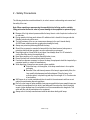
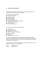
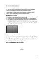
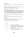
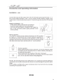
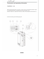
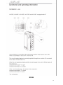
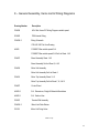
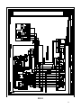
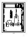
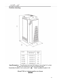
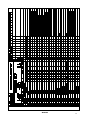
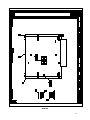
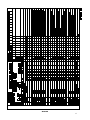
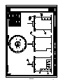
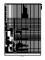
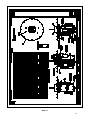
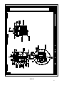
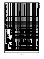
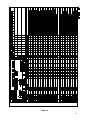
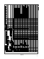
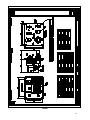
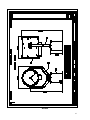
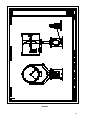
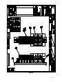
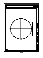
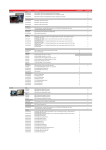
User Instruction & Installation Manual FX560 Remote Control 3 Kilowatt Xenon Searchlight Product Reference Number: A6065 – FX560RC 3Kw 400v 3 phase PO Number 90.274.0028 Manufacturers details: Distributor details: Francis Searchlights Ltd Union Road, Bolton Lancashire, BL2 2HJ, UK Tel: +44 (0) 1204 558960 Fax: +44 (0) 1204 558979 http://www.francis.co.uk E-mail: [email protected] Manual Part Number: C24608 Issue : 4 VDB001 1 CONTENTS 1 - Introduction 2 - Safety Precautions 3 - Technical Information BD001/003 - Unpacking and Installation Instructions EC001 - Electrical Installation EC002/008 - Operating Instructions FB001/003 - Fault Finding 4 5 6 7 8 10 - Maintenance and Servicing FC001 - General Assembly & Wiring Diagrams AD001/006 AS001/016 BB001 BD004/006 - Spare Parts List 11 - Certificates 9 CV001 CD001/002 CW001 2 1 - Introduction It is imperative that this manual is read carefully and understood before installing your equipment. For your future reference please keep this manual in a safe place. Thank you for specifying a product from the Francis Searchlights range. All Francis products are designed to give complete customer satisfaction and are manufactured to the highest engineering standards in order to ensure optimum performance and service life. The Francis Xenon range combine features proven over many years service in the most hazardous conditions in both marine and land installations. In order to prolong the life and performance of your product, we recommend that you only specify Francis Searchlights spare parts. This will also ensure that any warranties on your equipment will not be invalidated. Information on spares ordering and parts is provided in this manual. Should you ever need to contact Francis Searchlights Ltd. regarding your equipment, please quote the Product Serial Number at all times. Back To Top 3 2 - Safety Precautions The following instructions must be adhered to, in order to ensure a safe working environment and the safety of the user. Note: When unpacking or manoeuvring the searchlight into its fixing position, suitable lifting points must be used in order to prevent damage to the equipment or personal injury. Because of the high internal pressure within the lamp, there is a risk of explosion in either a hot or cold state; During operation this lamp emits intense UV radiation which is harmful to the eyes and skin. Suitable protection should be worn; The high luminance of the arc can cause severe damage to the eye if viewed directly. ALWAYS wear suitable protective goggles when viewing the lamp; Always use protective jackets supplied with the lamp; Should it be necessary to examine the lamp with the front bezel removed, always use a protective shield and wear goggles to ensure a safe working environment; Searchlights get hot. Never touch the unit when lit and always allow 15 to 20 minutes for cooling down after turning the searchlight off; Never place anything on or cover the searchlight when in use; Ensure the lamp has cooled sufficiently before removal; If undue force appears necessary to remove the lamp, the equipment should be inspected by a competent person or contact the manufacturer; When disposing of lamps there are several options available: Return the lamp, via the supplier, to the lamp manufacturer in its complete packaging Because of the cold internal pressure of the lamp is approximately 8 bar, the lamp must first be depressurized before disposal. Place the lamp, in its protective jacket, in a plastic bag and drop from a height of 1 to 2 metres onto a hard surface; XBO lamps do not contain materials which are harmful to the environment and thus are not subject to special waste disposal regulations; Due to the vast range of lamps available it may appear possible that more powerful lamps can be used in the equipment than for which it was designed. Even when the unit will physically accept a higher wattage lamp, this substitution is not recommended and is dangerous. This action will also void any warranties on the equipment. Always refer to the lamp manufacturers technical data when dealing with lamps. Back To Top 4 3 - Technical Information This product has been designed to operate in accordance with the product specification. The FX560RC 3000 watt searchlight has the following features: All marine grade materials and fixings; Electronic power supply unit; Parabolic glass reflector; Stove enamel painted; 385° horizontal rotation; Vertical movement 90° to -20°; Motor speed 0-20°/sec fast, 0-10°/sec slow (Pan) 0-10°/sec fast, 0-5°/sec slow (Tilt); Remote focus facility; Internal self-regulating heater. The searchlight also performs to the following optical data: Xenon light source; Lamp Wattage - 3000 Watts; Supply voltage – 400v & 240v; Peak Beam Candlepower – 175 Million lux; Range – 13,250 metres; Divergence - 1.5°; Temperature range: -50°C to +50°C In order that the searchlight operates correctly it is imperative that competent personnel are responsible for the installation, operation and servicing of this equipment. Failure to adhere to this advice may cause premature failure or incorrect operation of the searchlight, which may damage the equipment or cause personal injury. Technical information on the Power Supply Unit and Irem Ignitor are included overleaf. For more detailed information please contact the manufacturer. PSU ref: Ignitor ref: Model N3-100E (Irem) AS16040A (Irem) 5 6 BD001 7 8 BD002 9 BD003 Back To Top 10 4 - Unpacking and Installation Instructions The following instructions should be read and fully understood prior to installing the equipment to ensure that the correct procedures are followed and all safety precautions are observed. Note: If the equipment has been in storage for a considerable amount of time, it is advisable to conduct a routine maintenance check on all parts before installation. Safety Precautions This equipment should not be connected to an electrical supply before being installed. Installation procedures should be adhered to in order to ensure a safe working environment and reduce the risk of damage or personal injury. Preparing the Mounting Position Mark out and drill the fixing holes through the deck and bolt the searchlight base securely On an uneven surface it is necessary to use a suitable sealant, such as silicone in order to ensure a weatherproofed joint. If anti-vibration mounts are to be fitted, the fixing holes for the mounts should also be marked out and drilled. Prior to manoeuvring the searchlight into its’ fixing position, the AV mounts should be fitted to the base. When in the desired position, bolt the searchlight firmly down. EC001 Back To Top 11 5 - Electrical Installation For safety purposes, only competent personnel should perform the electrical installation. All equipment should be installed to current Electrical Regulations and Standards. In order to obtain the maximum light output from the searchlight, it is essential that the full operating voltage of the lamp fitted be applied to the lampholder contacts. Method of Electrical Connection 1) Disconnect the supply before working on the electrical system; 2) The searchlight must be connected to a fused electrical supply, using suitably sized cable; 3) If the searchlight is located a considerable distance from the mains supply, provision must be made in the cable size in order to overcome the voltage drop. The PSU should NOT be positioned no more then 14 meters away from the Searchlight. The following table below indicates the maximum length of cable to be used for the AC supply cable, from the control panel to the searchlight: Searchlight 240v 3Kw Cable Size (mm²) Distance Max 1.5 23 MTRS 2.5 39 MTRS 4 64 MTRS 6 99 MTRS 10 168 MTRS 4) Whenever possible cable terminations should be made below deck and with approved terminal devices; 5) If a spare auxiliary fuse or circuit breaker is not available, one of the correct type and rating should be fitted and connected to a positive supply. It is advisable to locate a bus bar or main connection and avoid any direct connection to the supply: Note: This equipment must be earthed. EC002 12 Installation Guidelines A typical installation and connection routine for the searchlight with a Variable Speed Gearbox is as follows: Referring to wiring diagram C24609, a 240v supply is fed to the Joystick Control Panel, which then provides a common feed to the Motor Gearbox and the Searchlight. A separate 400v 3 phase & earth supply is fed to the power supply unit. Cables required to be connected by the customer: 4 core 16mm cable from the Motor Gearbox to the PSU, doubling up the pairs (15 Metres supplied) 3 core 1.5mm cable from the Motor Gearbox to the Joystick Control Panel (10.5 Metres supplied). 4 core 1.5mm cable from the Motor Gearbox to the Joystick Control Panel (11 Metres supplied). 12 core 1.5mm cable from the Motor Gearbox to the Joystick Control Panel (11 Metres supplied). 3 core 1.5mm cable from the Joystick Control Panel to the PSU (4.5 Metres supplied) The Mains cable to the Joystick Control Panel and the Mains cable to the PSU both to be supplied by the customer. The searchlight head is pre-wired along with the connecting cable to the motor gearbox. Basic Operation When the searchlight is switched on a DC voltage from the power supply unit is feed to the lamp. The ignitor ionises the gas within the lamp and this strikes the light. All other facilities are fed via the joystick control panel and motor gearbox. IMPORTANT:~ Remote operation Before switching on the power supply unit via the on/off switch on the joystick Control Panel be sure the On/Off switch on the PSU is blocked by the mechanical lock to avoid untimely switching on, occurring for any reason. Before the searchlight is switched on make sure the fans are turned on to avoid any overheating problems. EC003 13 EC004 14 EC005 15 EC006 16 Fitting instructions for the 3Kw xenon lamp Referring to the diagram overleaf: 1) Unfasten the ten latches (A) on the front and rear of the searchlight; 2) Remove the front bezel (B) and rear bezel (C) assemblies; 3) Unscrew the two M6 hexagon screws (D) from the front lampholder mounting block (E) and remove the front lampholder assembly from the mounting bracket; 4) Loosen the knurled screw on the front (F)and rear (G) lampholder assembles; 5) The lamp can now be inserted, make sure that the negative (cathode) end of the lamp is towards the rear of the searchlight; 6) Tighten the knurled screw (G) on the rear lampholder assembly to hold the lamp in position; 7) Fasten the front lampholder mounting block back in position, it will be necessary to pull the front socket against its spring to fit over the lamp. When in place tighten the front knurled screw (F); 8) Fasten the front and rear lampholder leads as wiring diagram, ensuring the connections are secure; 9) The front bezel and rear bezel can now be replaced. 10) Removal is the reverse of the above. EC007 17 Back To Top EC008 18 6 - Operating Instructions This equipment is designed for use out of doors, in free air. Never place anything on, or cover, the searchlight when in use as this may present a hazard. All PSU should be housed below deck/in doors. Never leave the PSU exposed to weather conditions. The searchlight can be remotely positioned via the joystick control panel, with the facility for movement up, down, left and right. The speed of movement depends on the more pressure applied to the joystick the faster the searchlight moves. When in the desired position the joystick should be released so that it returns to its’ home position, dead centre. The variable speed gearbox has a fast and slow setting. You activate this by switching the controller switch on the control panel then selecting fast or slow. The beam of the searchlight can be adjusted to give a variety of beam types. Using the yellow remote focus button on the joystick panel, the desired beam can be achieved for any particular application. The beam will move continuously through ‘spot’ to ‘flood’. In order to fix the beam type, simply release the button at the desired position. The heaters specified on this equipment are self-regulating and will shut off when they reach the dew point temperature. This product should not be used for any purpose other than for which it was designed. Any modifications to the product should not be undertaken without consulting the manufacturer. FB001 19 Setting to Work Safe service in use necessitates the strict observance of the following precautions. Any article fabricated from quartz or glass is inherently fragile and care should therefore be taken, at all times, when handling lamps; Eye protection must be worn when handling lamps that have been removed from their packaging materials. The protective jacket should not be removed from the lamp for safety reasons, as there is a remote possibility of the lamp shattering violently, especially if it is subjected to mechanical shock or vibration; Ensure that the power rating of the Xenon lamp to be fitted is suitable for the lamphouse and power supply equipment (rectifier); Always isolate the equipment from the supply before inserting a lamp; Before inserting the lamp ensure that all contacts are clean. Contacts must be renewed at the slightest sign of corrosion. Sanding or filing down corroded areas is not recommended as this will only make the conducting surface between the pin and lampholder smaller, thus causing the lamp to overheat; The inert gas (Xenon) used in XBO lamps is under a pressure of several bar even when the bulb is cold. FOR SAFETY REASONS THE LAMP MAY ONLY BE INSERTED INTO THE LAMPHOUSE WITH THE PROTECTIVE JACKET FITTED; Do not twist or bend the fused quartz bulb when fitting the lamp as mechanical stresses MUST be avoided; Ensure that the spring contacts firmly surround the pins on the cap of the lamp. Do not apply unnecessary force when tightening the screws; After inserting the lamp, ensure that there is sufficient axial play in the lampholder. The lamp must be capable of unimpeded expansion when it warms up to operating temperature. Mechanical forces must not be applied to the fused quartz bulb; Electrical leads must be arranged in such a way that there is a sufficient air gap (approximately 40mm) between them and the lamphouse, in order to prevent flashovers from the ignition voltage. All flexible leads must have strain-relieving clamps; Before putting the lamp into service for the first time, check the polarity of the electrical connections. INCORRECT POLARITY WILL CAUSE IMMEDIATE DESTRUCTION OF THE LAMP; Before the protective jacket is removed, suitable protection must be worn i.e face mask and gloves with wrist protection; Never touch the quartz bulb with bare hands, as fingerprints will make the glass cloudy and cause a severe loss of light. This may also cause recrystallisation and thus weaken the bulb material. Should the bulb be inadvertently touched, remove fingerprints with methylated spirit and a clean, soft paper towel. The bulb should then be wiped with distilled water. NOTE: ALWAYS WEAR MASK AND GLOVES DURING CLEANING); All packaging and the protective jacket must be retained for re-use. Whenever removing a lamp, the protective jacket must always be used for safety reasons; FB002 20 Notes: 1) XBO lamps are designed for dc operation only. The dc current may only be varied within the limits of the current control range. An XBO lamp operates best at rated current; over the life of the lamp, the current may be increased to its maximum value to compensate for loss of light. The output of the lamp can be reduced by operating the lamp at minimum current but this does not prolong the life of the lamp; 2) For safety reasons, XBO lamps should be replaced once they reach the end of their average lamp life, and not later than 1.25 times their average lamp life. After this time there is an increased risk of the lamp exploding; 3) The anode (positive cap marked ‘+’) must be on top when the lamp is inserted in the vertical position. If the anode is incorrectly inserted the arc will be unstable, the bulb will blacken more quickly and the lamp will prematurely fail; 4) The HT lead from the high voltage terminal of the ignitor, must be connected to the cathode (negative cap marked ‘-‘). If the lamp is connected with the wrong polarity it will be irreparably damaged after a very short time. 5) In all circumstances the lamp manufacturers data should be referred to when dealing with lamps. FB003 Back To Top 21 7- Fault Finding All fault finding must be conducted by a competent person or qualified Electrical Engineer. Please refer to the following table for the trouble-shooting of Xenon lamps. Fault Wrong Polarity Cause Lamp incorrectly fitted Faulty wiring Cap overheated Cap temperature above 230°C Faulty contacts Cooling equipment defective Arc unsteady Lamp operated outside current control range Magnetic stabilisation for horizontal operation defective Crack in graded seal caused by overheated cap Maximum cap temperature 230°C Lamp operated outside current control range Lamp service life exceeded Current ripple too high Auxiliary mirror incorrectly adjusted Lamp operated too long in same position Bulb draws in air Glass erosion on fused quartz bulb Electrodes damaged Premature blackening Asymmetrical blackening of lamp (in horizontal burning position) Remedy Anode (large electrode) must always be on top in vertical burning position Check polarity, transpose connections if necessary Check terminals, tighten or renew Check cooling equipment and replace if necessary Correct current setting Check magnetic stabilisation Check terminals - tighten or renew Correct current setting Check meter Have power supply inspected Adjust auxiliary mirror Turn lamp through 180° after half service life 22 Failure of Lamp to Ignite In the event of the xenon lamp failing to light the following steps should be taken: 1) Check that the mains supply is connected to the input of the PSU. On operating the switch, if the lamp does not light, switch off mains supply and check all fuses; 2) On pressing remote starting switch the lamp still does not ignite, check the searchlight head. On your command get an operator to activate the starting switch for approximately 10 seconds. During this time listen for any noise (cracking or hissing) coming from within the barrel. If this arcing is heard switch off the supply at the mains. Remove the rear bezel to expose the two supply leads to the xenon lamp. Using a dry cloth wipe these leads to remove any dust, moisture or condensation that may have formed around the inside of the barrel. Replace the rear bezel, ensuring the latches are securely fastened, and perform the check again, listening for the cracking. If the lamp still fails to ignite, switch off at the mains and replace the xenon lamp in accordance with the safety procedures within this manual and the manufacturers information. Any further tests to be carried out with regards to lamp failure must be conducted by a competent electrical engineer and should not be carried out in an explosive atmosphere. 3) Before a xenon lamp will ignite, the electrically insulated gas between the electrodes must be ionised. This is done by the ignitor which produces a high frequency voltage (up to 30,000 volts or higher). The ignitor is activated by switching the lamp on and a crackling or hissing noise should be heard. The ignitor is housed within the rear of the searchlight barrel. This is a totally encapsulated unit and repair is not advised. If found to be faulty a new ignitor must be fitted. Failure of Remote Focus Facility The remote focus mechanism is controlled by a small electric motor situated at the rear of the searchlight barrel. If the focus of the light fails the following procedure should be adopted: 1) Remove the rear bezel from searchlight barrel and examine focus mechanism. If parts have become loose, tighten fasteners. The mechanism operates on a lever action and this should be checked for correct positioning; 2) If the mechanism is okay, check the supply to the motor. This can be done by simply placing a multi-meter across the motor terminals; 3) If supply is present, this indicates that the motor has failed. Replace the focus motor ensuring that the assembly is correct; 4) If no supply is present there is a fault in the Motor Gearbox or on the Joystick Control Panel. This should be examined and rectified accordingly. Note: If a fault occurs on the motor gearbox, the unit should be returned to Francis Searchlights Limited for fault evaluation and repair. Back To Top 23 8 - Maintenance and Servicing In order to prolong the service life and performance of your searchlight, the following maintenance guidelines are recommended: Maintenance checks should be conducted before very voyage or at least every three months; Before checking, disconnect the equipment from the supply; Visually inspect the condition of the equipment; Any major or minor structural damage should be rectified immediately in order to reduce sympathetic wear; After inspection it may be necessary to clean the inside of the searchlight. The following procedure should be adhered to: Remove the front bezel; Clean the front glass inside and out using a proprietary glass cleaner or metal polish; Clean the reflector if required; Check the reflector mounting gaskets. If signs of corrosion or damage are evident, replace as necessary; Ensure that the lampholder is free from corrosion or other damage; Check earthing point for conductivity; It is advisable to check all seals and gaskets for signs of degradation. Renew if necessary; Upon completing all maintenance requirements the searchlight should be tested for full working order ( approximately 20 minutes). If in any doubt as to the correct servicing procedures to adopt please contact your distributor/agent or the manufacturer who will be able to advise the best course of action for your product. FC001 Back To Top 24 9 – General Assembly, Items List & Wiring Diagrams Drawing Number Description C24609 400v 3Kw Xenon RC Wiring Diagram variable speed S36422 PSU Internal Wiring C24609-2 Wiring Schematic PSU N3 100E Out Line Drawing A6065 FX560RC 3Kw variable speed G.A. FX560RC 3Kw variable speed G.A Set List Sheet 1 & 2 C24607 Barrel Assembly Sheet 1 & 2 Barrel Assembly Set List Sheet 3, 4 & 5 C24606 Motor Unit Assembly Motor Unit Assembly Set List Sheet 6 C24616 Motor Top Assembly Sheet 1 & 2 Motor Top Assembly Set List Sheet 7, 8, 9 & 10 C24627 Control Panel A6065-2 G.A. Dimensions, Weight & Materials Breakdown A6065-3 G.A. Section View C22470 Terminal Rail Assembly C24606-2 Motor Unit Cable Entries C21501 Motor Unit Fixing Holes Back To Top 25 BD004 26 BD005 27 BB001 28 Heat Dissipation: - The efficiency n of the N3-E series is more than 0.8, so that you can lose maximum (in heat) the following watts. DeltaP[W]=Pout[W]* (1/n-1) with n=0.8 DeltaP max[W]=Pout[W]* 0.25 Mount PSU in Vertical position as shown. BD006 29 AS001 30 AS002 31 AS003 32 AS004 33 AS005 34 AS006 35 AS007 36 AS008 37 AS009 38 AS010 39 AS011 40 AS012 41 AS013 42 AS014 43 AS015 44 AS016 45 AD001 46 AD002 47 AD003 48 AD004 49 AD005 50 AD006 51 10 - Spare Parts List The following spare parts can be ordered directly from the manufacturer: Part Number Description C24635-00 C12081-00 C24597-00 D24177 C14143-00 C14142-00 C22347-00 C22941-00 C20881-00 C20569-00 C15458-00 C15459-00 C23277-01 C06779-00 Power Supply Unit (240v) Ignitor (240v) Fan (240v) 3Kw Xenon Lamp Switch 10A - On/Off Switch – Focus Joystick Switch (Controller/speed) Front Glass Front/Rear Bezel Gasket Motor - Remote Focus Bearing Heater & Fuse Assembly Reflector Motor Gearbox Spares C22403-01 C22287-00 C22380-00 C22382-00 C24030-01 C24060-01 C23530-00 C22381-00 C21225-00 C23237-00 Pan Motor S/Assy Tilt Motor Microswitch no lever Microswitch with lever ‘I’ Drive Pan Speed Controller ‘I’ Drive Tilt Speed Controller P.S.U. Pedestal Top Sealing Gasket Pedestal Cover Gasket Heater (240v 60w) In order to prolong the life and performance of your product, we recommend that you only specify Francis Searchlights spare parts. This will ensure that any warranties on your equipment will not be invalidated. When ordering spare parts please contact the Sales Department at Francis Searchlights Limited. Please quote searchlight model and serial number at all times. This will enable a fast response to your spares’ requirements. Back To Top 52 CV001 53 CD001 54 CD002 55 CW001 56