1
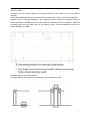
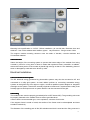
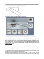
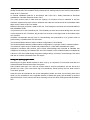
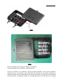
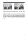
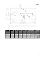
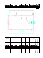
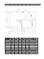
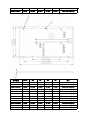
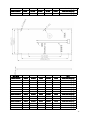
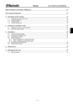
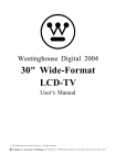
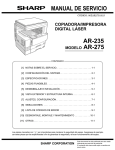
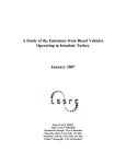
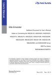
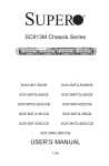
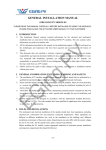
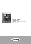
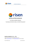
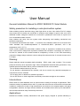
User Manual
General Installation Manual for ZDNY SERIES PV Solar Module.
Safety precaution for installing a solar photovoltaic system
Solar modules produce electrical energy when light shines on their front surface.The DC voltage
may exceed 30v.If modules are connected in series,the total voltage is equal to the sum of the
individual module voltages.If modules are connected in parallel,the total current is equal to the
sum of individual module currents.
Keep children well away from the system while transporting and installing mechanical and
electrical components.
The electrical characteristics are within ±10 percent of the indicated values of Isc,Voc,and Pmax
under standard test conditions(irradiance of 100mW/cm2,AM1.5 spectrums, and a cell
temperature of 25℃(77℉)).
Under normal conditions,a photovoltaic module is likely to experience conditions that produce
more current and/or coltage than reported at standard test conditions. Accordingly, the values of
Isc and Voc marked on this module should be multiplied by a factor of 1.25 when determining
component voltage ratings,conductor current ratings,fuse sizes and size of controls connect to the
PV output.
Warning:
Please read this manual completely before installing ZDNY series solar modules. This module
produces electricity when exposed to light. Follow all applicable electrical safety precautions. Only
qualified personnel should install or perform maintenance work on this module.
Do not handle modules when they are wet.
Do not attempt to disassemble the modules, and do not remove any attached nameplates or
components from the modules.
Do not apply paint or adhesive to module top surface.
Do not use mirrors or other magnifiers to artificially concentrate sunlight on the modules.
Introductions:
ZDNY series PV Solar Modules come in various sizes to satisfy a full range of applications. Each
module is made of crystalline-silicon cells. To protect the cells from the most severe-environmental
conditions, modules are made of high transmission rate and low iron tempered glass, anti-aging
encapsulation material, and high climate resistant and insulation back sheet by hot laminations,
with anodized Aluminum alloy frame and junction box.
Applications:
Modules are reliable, virtually maintenance free power supply, deigned to operate efficiently in
1
sunlight. By modules, the solar radiant energy is transformed into electrical energy for using.
Modules, usually be used as one fittings of PV Solar System. A set of basic PV solar system is
consisted of PV solar module, controller, inverter, and storage battery.
Modules can be used in roof PV solar systems, PV stations, building, and other eletrical
generation applications etc widely.
MECHANICAL INSTALLATIONS
Mounting Site
Modules can be used on land except for corrosive salt area and sulfurous area.
Excluded applications include, but are not limited to, installations where modules are likely to
come in contact with any salt water or where likely to become partially or wholly submerged in
fresh or salt water, examples of which include use on boats, docks and buoys, Don’t install
modules in a location where it would be immersed in water or continually exposed to water from a
sprinkler or fountain etc.
Modules are designed for a maximum allowable design pressure of 50 pounds per square foot,
about 2400 Pa, which may correspond to a nominal wind speed of approximately 130 km/h in
certain circumstances.
Actual maximum allowable wind speed may be influenced by module type, mounting configuration,
location, and other factors. In no case should modules be exposed to pressures greater than 50
pounds per square foot of uniformly dis tribute wind, snow, or other loading.
Not install modules near naked flame of flammable materials.
When choosing a site, avoid trees, buildings or obstructions. Modules should be mounted to
maximize direct exposure to sunlight and to eliminate or minimize shadowing. Even partial
shadowing can substantially reduce module and system output. Furthermore, partial shadowing
can elevate the shaded portions internal temperature, which may lower output and shorten module
life.
Orientation of installations
Modules may be mounted at any angle from a vertical orientation to a horizontal one. The
appropriate fixed tilt angle and azimuth orientation should be used in order to maximize the
exposure to sunlight.
Incorrect orientation of modules installation will result in loss of power output. Modules connected
in series should be installed at same orientation and angle. Different orientation or angle may
cause loss of power output due to difference of amount of sunlight exposed to the modules.
In the Northern Hemisphere, modules should face south, and in the Southern Hemisphere,
2
modules should face north.
Module tilt angle
Modules produce the most power when they are pointed directly at the sun. For installations where
modules are mounted to a permanent structure, modules should be titled for optimum winter
performance. As a rule, if the PV system power production is adequate in the winter, it will be
satisfactory during the rest of the year. The module tilt angel is measured between the modules
and the ground.
Maintenances
It is not uncommon for a remote site to be checked but once per year. Under most conditions,
normal rainfall is sufficient to keep the module glass clean. IF diet build-up becomes excessive,
clean the glass with a soft cloth using mild detergent and water. Modules that are mounted, flat
should be cleaned more often, as they will not self-clean as effectively as modules mounted at a
150 tilt or greater.
It is advisable to perform periodic inspection of the modules for damage to glass, back-skin, frame,
and support structure.
Check electrical connections for loose connections and corrosion. Check if mounting support
structure and modules are loose. Check connections of cables, connectors, and grounding.
Change modules must be the same kind and type, if need.
Modules can operate effectively without ever being washed, although removal of dirt from the front
glass can increase output. The glass can be washed with a wet sponge or cloth. Wear rubber
gloves for electrical insulation.
Mechanical Installation
Selecting the location
1.
1.Selecting
Select a suitable location for installation of the module.
The module should be facing true south in northern latitudes and true north in southern latitudes
for best power production.
For detailed information on the best elevation tilt angle for the installation, refer to standard solar
photovoltaic installation guides or a reputable solar installer or systems integrator.
The module should not be shaded at any time of the day.
Do not use module near equipment or in locacollected.
Selecting the proper support frame
2.Selecting the proper support frame
3
Always observe the instructions and safety precautions included with the support frame to be used
with the module.
No attempt must be made to drill holes in the glass surface of the module. To do so will void the
warranty.
Do not drill additional mounting holes in the frame of the module. Doing so will void the warranty.
Modules must be securely attached to the mounting structure using four mounting points for
normal installation. If additional wind or snow loads are anticipated for this installation, additional
mounting points are also used. Refer to the drawing, below. Load calculations are left to the
system designer or installer.
Mounting holes for normal installation
For high wind and snow-loads, these mounting holes must also be used
4
Mounting hole specification is 12-R3.5-7,When installation, pls use M6 bolt, Diameter 8mm and
thickness 1 mm of the stainless steel washer, tighten ways as above,fixing moment 12Nm.
The support module mounting structure must be made of durable, corrosion-resistant and
UV-resistant material.
Ground mount
3.
3.Ground
Select the height of the mounting system to prevent the lowest edge of the module from being
covered by snow for a long time in winter in areas that experience heavy snowfalls. In addition,
assure the lowest portion of the module is placed high enough so that it is not shaded by plants or
trees or damaged by sand and stone driven by wind.
Electrical Installation
Grid-connected electrical system
1.
1.Grid-connected
The DC electrical energy generated by photovoltaic systems may also be converted to AC and
connected to a utility grid system. As local utilities’ policies on connecting renewable energy
systems to their grids vary from region to region, consult a qualified system designer or integrator
to design such a system. Permits are normally required to install such a system and the utility must
formally approve and inspect such a system before it can be connected to the grid.
Grounding
2.
2.Grounding
The module frame must be properly grounded (refer to NEC clause 250). The grounding wire must
be properly fastened to the module frame to assure good electrical
contact.Use the recommended type, or an equivalent, connector for this wire.
If the support frame is made of metal, the surface of the frame must be electroplated and have
excellent conductivity.
The diameter of the earthing pole is M4, M3 stainless steel bolt is used and the fixing moment is
5
1.5NM. Put the M3 bolt into the earthling pole . Peel off one end of the Model AWG12 of the cable
and wind around M3 bolt ,screw down the slotted screw.
using stainless steel M3 screw and hardware as shown below.
Note please use 4mm diameter and 1mm thickness stainless steel washer while using
Further, buildup of hardware for mounting the grounding lug are the same—except for the M3
screw, an added lat washer is mounted directly under the M3 screw head. The star washer is itted
directly under the grounding lug and makes electrical contact by penetrating the anodized coating
of the aluminum frame, The screw assembly is further itted with a lat washer, then a split lock
washer and inally a nut to secure the entire assembly, as shown. Recommended torque of M3
screw assembly is 1.5NM .
General installation
3.
3.General
Do not use modules of different configurations in the same system.
Several modules are connected in series and then in parallel to form a PV array, especially for
application with a high operation voltage. If modules are connected in series, the total voltage is
equal to the sum of individual voltages.
For applications requiring high currents, several photovoltaic modules can be connected in parallel;
the total current is equal to the sum of individual currents.
Module is supplied with Multicontact connectors (PV GZX0601-1 to use for system electrical
connections).Use the National Electric Code to determine system wiring size (refer to NEC clause
6
310), type and temperature rating of conductors to be connected to the module’s connectors.
Wiring connected to the module’s wiring should be #12 AWG (minimum) and must be temperature
rated at 90°C (minimum).
In Canada installation shall be in accordance with CSA C22.1, Safety Standard for Electrical
Installations, Canadian Electrical Code, Part 1.
The cross section area of cable and the capacity of connector must be selected to suit the
maximum system short circuit current, otherwise the cable and connector will be overheated under
large current. Refer to NEC for details.
Module overcurrent protection, rated for DC use. Fuse ratings are as shown the enclosed tables of
this Installation Guide.
The junction box is with a breather port. The breather port must be mounted facing down and can
not be exposed to rain. Therefore, the junction box must be on the higher side of the module when
it is mounted.
Suntellite recommends that all work in commissioning and maintenance of a system must be
performed by a qualified solar PV technician!
The recommended maximum series l module configuration is 22 modules.
The recommended maximum parallel module configuration is 3 groups of serie- module numbers。
The maximum series array is 22sets and parallel array is 3 sets while assemble the system
experience conditions that produce more current and/orvoltage than reported at standard test
conditions. Accordingly, the valuesof ISC and VOC marked on this module should be multiplied by
a factor of 1,25 when determining component voltage ratings, conductor current ratings, fuse sizes,
and size of controls connected to the PV output."
Testing and replacing bypass diodes
Removing the bypass diodes should be done only by a competent PV technician and after the
module has been disconnected from the system.
Place module face down on a soft, lat surface Insert a 3mm lat screwdriver into the slot on the
junction box cover. (The cover has a sign of screwdriver). Gently pull up the four slots until the
cover been opened.
Insert the 3mm lat screwdriver into a hole alongside of diode and near one mounting hole of the
diode, pry the screwdriver in the opposite direction of diode and gently pull the diode up until the
lead comes free. Do the same in the other mounting hole of the diode, and repeat until the diode is
free.
7
0601
0701
Note the orientations of the polarity markings on the diodes.
The bypass diode type is 12SQ045,rated current 12A。
Check the resistance of the diodes by using the digital multimeter’s ohms scale. Resistance
should be low in one direction, then when leads are reversed on the diode’s terminals the
resistance should be high, as illustrated in the two pictures below. If a diode has a low resistance
in both directions, it is probably shorted. If it has high resistance in both directions it is probably
8
open. In either case it should be replaced.
Disclaimer of Liability
Because the use of this manual and the conditions or methods of installation, operation, use and
maintenance of photovoltaic (PV) product are beyond Suntellite ’s control, Suntellite does not
accept responsibility and expressly disclaims liability for loss, damage, or expense arising out of or
in any way connected with such installation, operation, use or maintenance.
No responsibility is assumed by Suntellite for any infringement of patents or other rights of third
parties, which may result from use of the PV product.No license is granted by implication or
otherwise under any patent or patent rights.
The information in this manual is based on Suntellite ’s knowledge and experience and is believed
to be reliable; but such information including product specification (without limitations) and
suggestions do not constitute a warranty, expresses or implied. Suntellite reserves the right to
change the manual, the PV produce, the specifications, or product information sheets without prior
notice.
PV modules on the back
back:
9
组件规格
ZDNY-80C36
Pmax
Voc
Isc
Vm
Im
尺寸
80W
21.97V
4.98A
17.39V
4.61A
mm
1200*550*45/40/35(mm
mm)
ZDNY-85C36
85W
22.11V
5.11A
17.71V
4.82A
mm
1200*550*45/40/35(mm
mm)
ZDNY-90C36
90W
22.32V
5.25A
18.11V
4.97A
mm
1200*550*45/40/35(mm
mm)
ZDNY-80CB36
80W
21.97V
4.98A
17.39V
4.61A
mm
1200*550*45/40/35(mm
mm)
ZDNY-85CB36
85W
22.11V
5.11A
17.71V
4.82A
mm
1200*550*45/40/35(mm
mm)
ZDNY-90CB36
90W
22.32V
5.25A
18.11V
4.97A
mm
1200*550*45/40/35(mm
mm)
10
组件规格
ZDNY-155C
Pmax
Voc
Isc
Vm
Im
尺寸
155W
V
43.72
43.72V
A
4.89
4.89A
V
34.44
34.44V
A
4.50
4.50A
1580*808*45/40/35
mm
1580*808*45/40/35(mm
mm)
ZDNY-160C
160W
43.94
V
43.94V
4.98
A
4.98A
34.77
V
34.77V
4.61
A
4.61A
1580*808*45/40/35
mm
1580*808*45/40/35(mm
mm)
ZDNY-165C
165W
44.08
V
44.08V
5.03
A
5.03A
35.07
V
35.07V
4.71
A
4.71A
1580*808*45/40/35
mm
1580*808*45/40/35(mm
mm)
ZDNY-170C
170W
44.22
V
44.22V
5.11
A
5.11A
35.42
V
35.42V
4.82
A
4.82A
mm
1580*808*45/40/35
1580*808*45/40/35(mm
mm)
ZDNY-175C
175W
44.44
V
44.44V
5.17
A
5.17A
35.75
V
35.75V
4.90
A
4.90A
mm
1580*808*45/40/35
1580*808*45/40/35(mm
mm)
ZDNY-180C
180W
V
44.64
44.64V
A
5.25
5.25A
V
36.21
36.21V
A
4.97
4.97A
mm
1580*808*45/40/35
1580*808*45/40/35(mm
mm)
ZDNY-185C
185W
V
44.80
44.80V
A
5.33
5.33A
V
36.65
36.65V
A
5.05
5.05A
mm
1580*808*45/40/35
1580*808*45/40/35(mm
mm)
ZDNY-188C
188W
V
44.80
44.80V
A
5.37
5.37A
V
36.92
36.92V
A
5.09
5.09A
mm
1580*808*45/40/35
1580*808*45/40/35(mm
mm)
ZDNY-189C
189W
V
44.80
44.80V
A
5.39
5.39A
V
36.92
36.92V
A
5.12
5.12A
mm
1580*808*45/40/35
1580*808*45/40/35(mm
mm)
ZDNY-190C
190W
V
44.80
44.80V
A
5.39
5.39A
V
36.92
36.92V
A
5.15
5.15A
mm
1580*808*45/40/35
1580*808*45/40/35(mm
mm)
ZDNY-195C
195W
V
44.88
44.88V
A
5.50
5.50A
V
36.94
36.94V
A
5.28
5.28A
mm
1580*808*45/40/35
1580*808*45/40/35(mm
mm)
ZDNY-200C
200W
V
44.95
44.95V
A
5.65
5.65A
V
36.95
36.95V
A
5.42
5.42A
mm
1580*808*45/40/35
1580*808*45/40/35(mm
mm)
ZDNY-205C
205W
V
45.03
45.03V
A
5.73
5.73A
V
36.97
36.97V
55A
5.
5.55A
mm
1580*808*45/40/35
1580*808*45/40/35(mm
mm)
ZDNY-155CB
155W
V
43.72
43.72V
A
4.89
4.89A
V
34.44
34.44V
A
4.50
4.50A
mm
1580*808*45/40/35
1580*808*45/40/35(mm
mm)
ZDNY-160CB
160W
V
43.94
43.94V
A
4.98
4.98A
V
34.77
34.77V
A
4.61
4.61A
mm
1580*808*45/40/35
1580*808*45/40/35(mm
mm)
ZDNY-165CB
165W
V
44.08
44.08V
A
5.03
5.03A
V
35.07
35.07V
A
4.71
4.71A
mm
1580*808*45/40/35
1580*808*45/40/35(mm
mm)
ZDNY-170CB
170W
V
44.22
44.22V
A
5.11
5.11A
V
35.42
35.42V
A
4.82
4.82A
mm
1580*808*45/40/35
1580*808*45/40/35(mm
mm)
ZDNY-175CB
175W
V
44.44
44.44V
A
5.17
5.17A
V
35.75
35.75V
A
4.90
4.90A
mm
1580*808*45/40/35
1580*808*45/40/35(mm
mm)
ZDNY-180CB
180W
V
44.64
44.64V
A
5.25
5.25A
V
36.21
36.21V
A
4.97
4.97A
mm
1580*808*45/40/35
1580*808*45/40/35(mm
mm)
ZDNY-185CB
185W
V
44.80
44.80V
A
5.33
5.33A
V
36.65
36.65V
A
5.05
5.05A
mm
1580*808*45/40/35
1580*808*45/40/35(mm
mm)
ZDNY-188CB
188W
V
44.80
44.80V
A
5.37
5.37A
V
36.92
36.92V
A
5.09
5.09A
mm
1580*808*45/40/35
1580*808*45/40/35(mm
mm)
ZDNY-189CB
189W
V
44.80
44.80V
A
5.39
5.39A
V
36.92
36.92V
A
5.12
5.12A
mm
1580*808*45/40/35
1580*808*45/40/35(mm
mm)
11
ZDNY-190CB
190W
V
44.80
44.80V
A
5.39
5.39A
V
36.92
36.92V
A
5.15
5.15A
mm
1580*808*45/40/35
1580*808*45/40/35(mm
mm)
ZDNY-195CB
195W
V
44.88
44.88V
A
5.50
5.50A
V
36.94
36.94V
A
5.28
5.28A
mm
1580*808*45/40/35
1580*808*45/40/35(mm
mm)
ZDNY-200CB
200W
V
44.95
44.95V
A
5.65
5.65A
V
36.95
36.95V
A
5.42
5.42A
mm
1580*808*45/40/35
1580*808*45/40/35(mm
mm)
ZDNY-205CB
205W
V
45.03
45.03V
A
5.73
5.73A
V
36.97
36.97V
55A
5.
5.55A
mm
1580*808*45/40/35
1580*808*45/40/35(mm
mm)
组件规格
ZDNY-230C
Pmax
Voc
Isc
Vm
Im
尺寸
W
230
230W
V
59.00
59.00V
A
5.13
5.13A
V
47.43
47.43V
A
4.85
4.85A
mm
1580*1060*45
1580*1060*45(mm
mm)
ZDNY-235C
W
235
235W
V
59.50
59.50V
A
5.20
5.20A
V
47.68
47.68V
A
4.93
4.93A
mm
1580*1060*45
1580*1060*45(mm
mm)
ZDNY-240C
W
240
240W
V
59.50
59.50V
A
5.24
5.24A
V
48.20
48.20V
A
4.98
4.98A
mm
1580*1060*45
1580*1060*45(mm
mm)
ZDNY-245C
W
245
245W
V
60.04
60.04V
A
5.30
5.30A
V
48.81
48.81V
A
5.02
5.02A
mm
1580*1060*45
1580*1060*45(mm
mm)
DNY-250C
W
250
250W
V
60.58
60.58V
A
5.36
5.36A
V
49.22
49.22V
A
5.08
5.08A
mm
1580*1060*45
1580*1060*45(mm
mm)
ZDNY-255C
W
255
255W
V
60.58
60.58V
A
5.40
5.40A
V
49.23
49.23V
A
5.18
5.18A
mm
1580*1060*45
1580*1060*45(mm
mm)
ZDNY-260C
W
260
260W
V
60.58
60.58V
A
5.51
5.51A
V
49.23
49.23V
A
5.29
5.29A
mm
1580*1060*45
1580*1060*45(mm
mm)
ZDNY-230CB
W
230
230W
V
59.00
59.00V
A
5.13
5.13A
V
47.43
47.43V
A
4.85
4.85A
mm
1580*1060*45
1580*1060*45(mm
mm)
ZDNY-235CB
W
235
235W
V
59.50
59.50V
A
5.20
5.20A
V
47.68
47.68V
A
4.93
4.93A
mm
1580*1060*45
1580*1060*45(mm
mm)
ZDNY-240CB
W
240
240W
V
59.50
59.50V
A
5.24
5.24A
V
48.20
48.20V
A
4.98
4.98A
mm
1580*1060*45
1580*1060*45(mm
mm)
ZDNY-245CB
W
245
245W
V
60.04
60.04V
A
5.30
5.30A
V
48.81
48.81V
A
5.02
5.02A
1580*1060*45
mm
1580*1060*45(mm
mm)
DNY-250CB
W
250
250W
V
60.58
60.58V
A
5.36
5.36A
V
49.22
49.22V
A
5.08
5.08A
1580*1060*45
mm
1580*1060*45(mm
mm)
ZDNY-255CB
W
255
255W
V
60.58
60.58V
A
5.40
5.40A
V
49.23
49.23V
A
5.18
5.18A
1580*1060*45
mm
1580*1060*45(mm
mm)
12
ZDNY-260CB
W
260
260W
V
60.58
60.58V
A
5.51
5.51A
V
49.23
49.23V
组件规格
ZDNY-190C54
Pmax
A
5.29
5.29A
Voc
Isc
Vm
Im
190W
33.10V
8.12A
25.68V
7.41A
尺寸
1482*992*45(mm)
ZDNY-200C54
200W
33.14V
8.20A
26.60V
7.53A
1482*992*45(mm)
ZDNY-210C54
210W
33.28V
8.33A
27.21V
7.72A
1482*992*45(mm)
ZDNY-220C54
220W
33.36V
8.42A
27.83V
7.91A
1482*992*45(mm)
ZDNY-230C54
230W
33.45V
8.56A
28.36V
8.12A
1482*992*45(mm)
ZDNY-190CB54
190W
33.10V
8.12A
25.68V
7.41A
1482*992*45(mm)
ZDNY-200CB54
200W
33.14V
8.20A
26.60V
7.53A
1482*992*45(mm)
ZDNY-210CB54
210W
33.28V
8.33A
27.21V
7.72A
1482*992*45(mm)
ZDNY-220CB54
220W
33.36V
8.42A
27.83V
7.91A
1482*992*45(mm)
ZDNY-230CB54
230W
33.45V
8.56A
28.36V
8.12A
1482*992*45(mm)
ZDNY-180P54
180W
32.40V
8.03A
25.70V
7.02A
1482*992*45(mm)
ZDNY-190P54
190W
32.80V
8.12A
26.01V
7.32A
1482*992*45(mm)
ZDNY-200P54
200W
33.35V
8.29A
26.10V
7.68A
1482*992*45(mm)
mm
1580*1060*45
1580*1060*45(mm
mm)
13
ZDNY-210P54
210W
33.73V
8.38A
26.52V
7.93A
1482*992*45(mm)
ZDNY-220P54
220W
34.06V
8.48A
27.10V
8.12A
1482*992*45(mm)
组件规格
ZDNY-210C60
Pmax
Voc
Isc
Vm
Im
210W
36.20V
8.10A
28.46V
7.39A
尺寸
1650*992*45(mm)
ZDNY-220C60
220W
36.40V
8.20A
29.16V
7.56A
1650*992*45(mm)
ZDNY-230C60
230W
37.00V
8.30A
29.76V
7.74A
1650*992*45(mm)
ZDNY-240C60
240W
37.76V
8.35A
30.34V
7.92A
1650*992*45(mm)
ZDNY-250C60
250W
37.85V
8.40A
31.17V
8.03A
1650*992*45(mm)
B60
ZDNY-210C
ZDNY-210CB
210W
36.20V
8.10A
28.46V
7.39A
1650*992*45(mm)
B60
ZDNY-220C
ZDNY-220CB
220W
36.40V
8.20A
29.16V
7.56A
1650*992*45(mm)
B60
ZDNY-230C
ZDNY-230CB
230W
37.00V
8.30A
29.76V
7.74A
1650*992*45(mm)
B60
ZDNY-240C
ZDNY-240CB
240W
37.76V
8.35A
30.34V
7.92A
1650*992*45(mm)
B60
ZDNY-250C
ZDNY-250CB
250W
37.85V
8.40A
31.17V
8.03A
1650*992*45(mm)
ZDNY-200P60
200W
36.00V
8.04A
28.15V
7.12A
1650*992*45(mm)
ZDNY-210P60
210W
36.30V
8.15A
28.40V
7.40A
1650*992*45(mm)
14
ZDNY-220P60
220W
36.80V
8.22A
28.65V
7.69A
1650*992*45(mm)
ZDNY-230P60
230W
37.20V
8.29A
29.28V
7.87A
1650*992*45(mm)
ZDNY-240P60
240W
37.70V
8.38A
30.20V
7.96A
1650*992*45(mm)
组件规格
ZDNY-250C72
Pmax
Voc
Isc
Vm
Im
250W
44.00V
7.96A
34.30V
7.29A
尺寸
1956*992*45(mm)
ZDNY-260C72
260W
44.10V
8.07A
35.00V
7.44A
1956*992*45(mm)
ZDNY-270C72
270W
44.15V
8.16A
35.49V
7.62A
1956*992*45(mm)
ZDNY-280C72
280W
44.31V
8.26A
35.95V
7.79A
1956*992*45(mm)
ZDNY-290C72
290W
44.49V
8.42A
36.65V
7.92A
1956*992*45(mm)
ZDNY-300C72
300W
44.62V
8.56A
37.62V
7.98A
1956*992*45(mm)
B72
ZDNY-250C
ZDNY-250CB
250W
44.00V
7.96A
34.30V
7.29A
1956*992*45(mm)
B72
ZDNY-260C
ZDNY-260CB
260W
44.10V
8.07A
35.00V
7.44A
1956*992*45(mm)
B72
ZDNY-270C
ZDNY-270CB
270W
44.15V
8.16A
35.49V
7.62A
1956*992*45(mm)
B72
ZDNY-280C
ZDNY-280CB
280W
44.31V
8.26A
35.95V
7.79A
1956*992*45(mm)
B72
ZDNY-290C
ZDNY-290CB
290W
44.49V
8.42A
36.65V
7.92A
1956*992*45(mm)
B72
ZDNY-300C
ZDNY-300CB
300W
44.62V
8.56A
37.62V
7.98A
1956*992*45(mm)
ZDNY-240P72
240W
43.00V
7.98A
34.10V
7.05A
1956*992*45(mm)
ZDNY-250P72
250W
43.60V
8.10A
34.20V
7.32A
1956*992*45(mm)
15
ZDNY-260P72
260W
44.00V
8.20A
34.32V
7.58A
1956*992*45(mm)
ZDNY-270P72
270W
44.49V
8.31A
34.74V
7.78A
1956*992*45(mm)
ZDNY-280P72
280W
44.75V
8.45A
35.28V
7.94A
1956*992*45(mm)
ZDNY-290P72
290W
45.20V
8.55A
35.75V
8.12A
1956*992*45(mm)
16