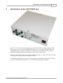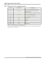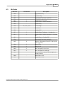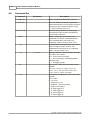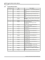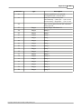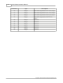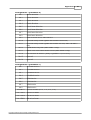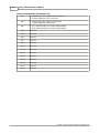
1
CNC1/CNC2 Installation Manual
Copyright © 2005 Conqueror Design and Engineering Ltd.
CNC1/CNC2 Installation Manual
Copyright © 2005 Conqueror Design and Engineering Ltd.
All rights reserved.
Any dispute about the use of this software and/or hardware or of these terms and conditions shall be resolved or
arbitrated under English Law.
Manuals and accompanying documentation may not be copied or printed for the purposes of training, advertising,
promotion or any other use without the permission of Conqueror Design and Engineering Limited.
Permission to copy and print manuals and documentation for personal use is granted to the owner/user of the
software supplied.
All trademarks are acknowledged to be the property of their respective owners.
This manual produced on 27/01/2005.
Warranty
This software and/or hardware and accompanying documentation are provided 'as-is' and are not warranted to be fit
for any specific purpose or usage.
The use of this software and/or hardware is undertaken at your own risk and Conqueror Design and Engineering
Limited will not be responsible for any loss of data, time or income resulting from the use of this software and/or
hardware.
Contents
I
Table of Contents
Part 1 Disclaimer of Liability and
Limitation of Warranty
1
Part 2 Introduction to the CNC1/CNC2
box
2
1 Front panel
...................................................................................................................................
controls
3
2 Rear Panel
...................................................................................................................................
Connections
4
RS232 Serial Interface
......................................................................................................................................................... 5
Spindle Motor control
.........................................................................................................................................................
plug
6
Relay drives plug
......................................................................................................................................................... 7
Stepper motor plug
......................................................................................................................................................... 8
Feed-back/Encoder/Limit-switch
.........................................................................................................................................................
plug
9
3 Spare...................................................................................................................................
and replacement plugs
10
Part 3 Manual Operation without a
Computer
11
Part 4 Appendices
12
1 Compatible
...................................................................................................................................
Motors
12
2 G-Codes
................................................................................................................................... 13
Additional G-Codes
.........................................................................................................................................................
for Lathe Operations
14
Additional G-Codes
.........................................................................................................................................................
for Milling Operations
15
3 M-Codes
................................................................................................................................... 16
4 Command
...................................................................................................................................
Set
17
5 Control
...................................................................................................................................
Parameters
19
Index
24
Copyright © 2005 Conqueror Design and Engineering Ltd.
I
1
1
CNC1/CNC2 Installation Manual
Disclaimer of Liability and Limitation of Warranty
Where the CNC1/CNC2 box is supplied as a component and not as part of a complete
control system it is assumed that the purchaser has sufficient electrical and electronic
knowledge to handle the component competently.
It is further assumed that the purchaser has sufficient knowledge of safe working practices
and the relevant Health & Safety regulations which apply to working with electrical and
electronic systems to work safely with the component.
Conqueror Design and Engineering Limited will not accept any liability for any damage to
systems or personnel that may result from the incorrect installation or usage of the
hardware supplied. Nor will Conqueror Design and Engineering Limited replace or repair
any supplied equipment that has been damaged as a result of such incorrect misuse or
installation.
Copyright © 2005 Conqueror Design and Engineering Ltd.
Introduction to the CNC1/CNC2 box
2
2
Introduction to the CNC1/CNC2 box
The CNC1/CNC2 box has been designed to control CNC lathes, milling machines, PCB
drills, routers, etc. In fact any machine which has 1, 2, 3 or 4 stepper motor driven axes.
The stepper motors can also, optionally, be controlled in a closed-loop mode with the
addition of standard quadrature encoders in either strip or rotary form.
The CNC1 box has a built in power supply which can output 10 Amps. The CNC2 box has
a built in power supply which can output 16 Amps.
A machine fitted with a CNC1/CNC2 can be operated in a simplified stand-alone manual
mode (for cleaning and maintenance, etc.) without requiring a host computer.
Copyright © 2005 Conqueror Design and Engineering Ltd.
3
2.1
CNC1/CNC2 Installation Manual
Front panel controls
The front panel controls are (from left to right) the axis jog buttons for the X and Y axis
(arranged in a cross around the green 'Enter'/BTN1 button), the Z axis jog buttons, 3 status
LEDs, the electronic hand-wheel and the power switch.
When in manual mode the jog buttons can be used to rapidly position an axis and then the
hand-wheel can be used to control the precise position. The hand-wheel automatically
switches to operate the last axis that was moved with one of the jog-buttons. The
electronic hand-wheel is rotated clockwise to move the axis in the positive direction and
counter-clockwise to move the axis in the negative direction.
Copyright © 2005 Conqueror Design and Engineering Ltd.
Introduction to the CNC1/CNC2 box
2.2
4
Rear Panel Connections
The rear panel contains the plugs for: the mains supply, the computer,
an AC/DC spindle motor (or any 10 Amp load), 12-volt relay drives, 4 stepper motors and
4 feed-back/encoder/limit-switch plugs. N.B. The CNC2 box has only 3 stepper motor
plugs and feed-back/encoder/limit-switch plugs.
AC Mains Inlet
The AC mains connector is a standard 'kettle' type plug. A mains cable is provided. The
socket includes a 2 Amp fuse - do not use a higher rated fuse... it will reduce the level of
protection!
Copyright © 2005 Conqueror Design and Engineering Ltd.
5
2.2.1
CNC1/CNC2 Installation Manual
RS232 Serial Interface
Pin
Signal
2
Receive Data (RCD)
3
Transmit Data (TXD)
7
Ready-To-Send (RTS)
8
Clear-To-Send (CTS)
5
Ground
The serial port is configured as a standard PC AT 9-pin port. A standard PC-AT to PC-AT
serial cable (a cross-over cable) can be used.
The default protocols are 19,200 baud, 8 data bits, no parity and 1 stop bit.
The board will use XON/XOFF flow controls by default.
Copyright © 2005 Conqueror Design and Engineering Ltd.
Introduction to the CNC1/CNC2 box
2.2.2
6
Spindle Motor control plug
Pin
Signal
1
Emergency stop
2
Emergency stop
3
Motor armature +
4
Motor armature -
5
Motor field +
6
Motor field -
7
Relay
8
Relay
9
Earth
The emergency stop circuit can be connected through any safety switches, cover switches,
etc. Provided it is unbroken the spindle, coolant and programmes can be run. If the
emergency stop circuit is broken then the spindle and coolant are forced off and any
programme running will be stopped... the machine can still be moved in manual mode. The
plug supplied has a link shorting pins 1 and 2.
The motor outputs (pins 3, 4, 5 and 6) are only available if the optional DCMOT1 card is
fitted.
The relay connection (pins 7 and 8) can carry 10 Amps @ 240 VAC. The circuit is closed
when spindle run is selected.
Copyright © 2005 Conqueror Design and Engineering Ltd.
7
2.2.3
CNC1/CNC2 Installation Manual
Relay drives plug
Pin
Signal
1
+12 Volt supply
2
Coolant relay
3
Relay 1
4
Relay 2
5
Relay 3
Each relay drive is capable of sinking 500 milli-amps of current but the combined current of
all relays should not exceed 1 Amp.
Copyright © 2005 Conqueror Design and Engineering Ltd.
Introduction to the CNC1/CNC2 box
2.2.4
8
Stepper motor plug
Pin
Signal
1
A phase +
2
A phase -
3
B phase +
4
B phase -
N.B. As delivered the stepper motor outputs are configured for 1 Amp/phase and for halfstepping with power-save enabled. To change these settings please refer to the manual for
the MPC5 card.
**WARNING** Never connect or disconnect a motor when the control box is powered
up. Allways turn off the control box and allow 2-3 minutes for the power-supply
capacitors to discharge before connecting or disconnecting motors. Failing to observe
this precaution could permanenty damage your control box!
Copyright © 2005 Conqueror Design and Engineering Ltd.
9
2.2.5
CNC1/CNC2 Installation Manual
Feed-back/Encoder/Limit-switch plug
Pin
Signal
1
+5 volt supply
2
A-channel of axis encoder
3
B-channel of axis encoder
4
0-volts/ground
5
Limit+
6
Limit-
7
X&Y&Z Plug - No
connection
E/U Plug - Single-slot
spindle encoder input
8
X&Y&Z Plug - No
connection
E/U Plug - Multi-slot spindle
encoder input
The power requirement of any encoder used should not exceed 100 milli-amps.
To connect a limit switch it should be connected between the limit switch input (pin 5 or 6)
and the ground connection (pin 4).
N.B. It is possible to use encoders which require a higher voltage than 5 volts by using the
12-volt supply from the relay plug and inserting a diode into the A and B lines. For
details please contact technical support.
Copyright © 2005 Conqueror Design and Engineering Ltd.
Introduction to the CNC1/CNC2 box
2.3
10
Spare and replacement plugs
Replacement plugs for the stepper motor connectors, feed-back/limit-switch connectors
and relay connector can be obtained from Maplin Electronics at http://www.maplin.co.uk.
Stepper motor plug is... 4-pin cable socket, code FK24B, 'LKG Line Socket 4-way'
Feed-back/limit switch plug is... 8-pin cable socket, code FK30H, 'LKG Line Socket 4way'
Relay connector is... 5-pin cable socket, code FK25C, 'LKG Line Socket 5-way'
A replacement/spare plug for the DC motor/10-Amp-relay/Emergency-Stop connector can
be obtained from RS Components (http://www.rswww.com) or Farnell Electronics
(http://www.farnell.co.uk).
RS Components code # 372-254, "Connector, circular, CPC, cable plug, 9 way, 13
shell".
Farnell Electronics code # 3195545, "RECEPTACLE, STD SLD CPC1 9 WAY".
Copyright © 2005 Conqueror Design and Engineering Ltd.
11
3
CNC1/CNC2 Installation Manual
Manual Operation without a Computer
If no computer is attached the machine can be used in a rudimentary manner using the
following jog-button and BN1 (button 1) and BN2 (button 2) combinations. the jogswitches operate as normal in manual mode when neither BN1 or BN2 is pressed.
Keys pressed
Action
BN1 & X+
Enter manual mode.
BN1 & X-
Exit manual mode.
BN1 & Y+
Turn spindle/spindle-relay on
BN1 & Y-
Turn spindle/spindle-relay off
BN1 & Z+
Toggle rapid and feed modes.
BN1 & Z-
Toggle coolant on/off.
BN2 & X+
Increase spindle speed (and turn on spindle if
necessary).
BN2 & X-
Decrease spindle speed (and turn off spindle
if necessary).
BN2 & Z+
Increase feed-rate.
BN2 & Z-
Decrease feed-rate.
If no button has been pressed for several minutes the machine will be switched out of
manual mode.
Copyright © 2005 Conqueror Design and Engineering Ltd.
Appendices
4
Appendices
4.1
Compatible Motors
12
The following motors have been tested with the CNC1 and CNC2 box...
Motor Size
Voltage
Current
Holding Torque
Holding
(W x H x L)
(Amps.)
(mNM)
Torque
(Oz-In)
23 Standard
11.2
0.33
320
45
57 x 57 x 40
3.4
1.0
340
48
2.3
1.5
330
47
1.5*
2.2*
310
44
23 Standard
10.1
0.44
650
91
57 x 57 x 52
5.0
1.0
690
98
2.3
2.1
640
91
23 Standard
4.2
1.6
1,090
154
57 x 57 x 67
3.4
1.9
1,130
160
2.8*
2.5*
1,140
161
23 Standard
3.5*
2.9
1,480
210
57 x 57 x 103
23 High Perf.
4.6
1.0
470
67
57 x 57 x 41
2.1
2.1
480
68
23 High Perf.
6.2
1.0
980
138
57 x 57 x 55
2.9
2.1
980
138
2.1*
3.0*
980
138
23 High Perf.
4.2
2.1
1,610
228
57 x 57 x 79
3.3*
3.0*
1,630
231
34 Standard
5.8
1.3
1,820
258
82 x 82 x 62
3.0
1.7
1,500
212
2.8*
3.1*
1,820
258
34 High Perf.
7.0
1.4
2,800
396
82 x 82 x 67
3.6*
2.8*
2,800
396
34 High Perf.
4.8*
2.8*
4,800
680
82 x 82 x 94
42 Standard
3.7*
3.4*
9,900
1,400
108 x 108 x 179
Torques quoted are for bi-polar drive.
Motors/voltages marked * are compatible with the CNC2 box only.
Other motors with similar voltages and current requirements will also be compatible
Copyright © 2005 Conqueror Design and Engineering Ltd.
13
4.2
CNC1/CNC2 Installation Manual
G-Codes
G-Code
Parameters
Description
G00*
X, Y, Z, E
Rapid Move
G01*
X, Y, Z, E, F
Feed Move
G02*
X, Y, Z, E, I, J, K, F, R
Arc Clockwise Move
G03*
X, Y, Z, E, I, J, K, F, R
Arc Counter-Clockwise Move
G04
S
Dwell. S=Seconds to delay.
G05*
P
G17
-
G18
-
G19
-
G28
X, Y, Z, E
Spline function (Bezier curve) (only
available when running with the EaziCNC
software)
Use XY plane for circular interpolation
(Top)
Use XZ plane for circular interpolation
(Front)
Use YZ plane for circular interpolation
(Side)
Home Axis
G40
-
Tool-nose compensation off (default mode)
G41
R
Tool-nose compensation Left-of-Line
G42
R
Tool-nose compensation Right-of-Line
G43
-
Tool-length compensation (positive)
G44
-
G45
-
Tool-length compensation (negative default mode)
Cancel Tool-length compensation.
G54
X, Y, Z, E
G70
-
G71
-
Imperial coordinates (only available when
running with the EaziCNC software)
Metric coordinates (default mode)
G90
-
Absolute coordinates (default mode)
G91
-
G92
X, Y, Z, E
Incremental coordinates (only available
when running with the EaziCNC software)
Set datum point.
Set home/reset position.
N.B. The E axis can also be programmed as U.
N.B. The codes marked with * are modal. Modal codes are active on any subsequent lines
that do not have a code given.
Copyright © 2005 Conqueror Design and Engineering Ltd.
Appendices
4.2.1
14
Additional G-Codes for Lathe Operations
G-Code
Parameters
Description
G33
X, Z, P, I
G80
-
G81*
X, Z, P
Turning cycle
G82*
X, Z, P
Taper cycle
G83*
X, Z, I, K, R, P
Arc Clockwise Cycle
G84*
X, Z, I, K, R, P
Arc Counter-Clockwise Cycle
G85*
X, Z, P
G86*
X, Z, P, I, K, R
G94
-
Threading(/synchronized) cut cycle. X is
pass offset (pass depth). P is pitch, I is end
pull-out, K is pass offset in Z and R is
number of passes.
Feed rates in mm./in. per minute
G95
-
Feed rates in mm./in. per spindle revolution
G96
-
Threading(/synchronized) cut. P is pitch, I
is end pull-out in X.
Cancel Canned Cycle
Facing Cycle
Constant surface speed.
Feed rate specified in mm. at 20.0 mm.
diameter.
Feed rate specified in inches at 1.0 inch
diameter.
N.B. The E axis can also be programmed as U.
N.B. The codes marked with * are modal. Modal codes are active on any subsequent lines
that do not have a code given.
Copyright © 2005 Conqueror Design and Engineering Ltd.
15
4.2.2
CNC1/CNC2 Installation Manual
Additional G-Codes for Milling Operations
G-Code
Parameters
Description
G50
-
G51
X, Y, Z, E
G55
-
G56
X, Y, Z, E
G80
-
Cancel/Complete Canned Cycle.
G81*
Z
Drill, Spot-Drill
G82*
Z, K
Peck Drill
G83*
Z, P
Tapping
G84*
Z
G85*
Z, P
Mirror Off. Cancel any mirrored axis.
Mirror. Mirror selected axis (around
coordinate given).
Offset Off. Cancel/Clear temporary origin
Offset. Set temporary origin.
Bore
Pocket cycle.
N.B. The E axis can also be programmed as U.
N.B. The codes marked with * are modal. Modal codes are active on any subsequent lines
that do not have a code given.
Copyright © 2005 Conqueror Design and Engineering Ltd.
Appendices
4.3
16
M-Codes
M-Code
Parameters
M00
-
Programme Stop
M01
-
Optional Stop
M02
-
Programme End (same as M30)
M03
S
Spindle Start Clockwise
M04
S
Spindle Start Counter-clockwise
M05
-
Spindle Stop
M06
R, T, X, Y, Z
Tool Change
M08
-
Coolant On
M09
-
Coolant Off
M13
S
Spindle Start Clockwise + Coolant On
M14
S
M15
-
Spindle Start Counter-clockwise + Coolant
On
Spindle Stop + Coolant Off
M30
-
Programme End (same as M02)
M47
R
M90
P
Return to Programme Start. R is the repeat
count (if given)
Relay P On
M91
P
Relay P Off
M92
P
Wait for input P to be Low
M93
P
Wait for input P to be High
M94
-
M98
-
Index tool-post. Indexes the tool-post (if
fitted) forward.
Motor Drives On
M99
-
Motor Drives Off
Copyright © 2005 Conqueror Design and Engineering Ltd.
Description
17
4.4
CNC1/CNC2 Installation Manual
Command Set
Command
Parameters
Description
Ctrl-B (#2)
-
Query. Used by the EaziCNC software.
Ctrl-E (#5)
-
Ctrl-N (#14)
-
<ESC>
-
@
-
D
n<CR>
EC
-
ES
-
Echo On. Echoes characters back to the
terminal and enables user friendly responses
(data sent to the terminal will have a tag,
i.e, "P0:0" instead of just "0").
Echo Off. Stops characters from being
echoed back to the terminal and disables
user friendly responses.
Escape. Stops any current moves or
commands. Clears the command buffers.
This command does not need to be
completed with a carriage return (CR).
At. Returns the current position and status
data in compressed hex format. This
command does not need to be completed
with a carriage return (CR).
Message-mode. Controls whether messages
are sent to the console.
n=0 - do not show messages
n=1 - show messages (including updates
when moving)
n=2 - debugging mode
Error Clear. Clears any error state on the
machine.
N.B. this clears user-stops, power-up
errors, etc. it will not and cannot clear
errors such as 'safety activated'.
Error Status. Displays the error code of the
machine.
Error codes...
0 - No error
1 - Stopped by user
2 - Stopped - safety activated
3 - Power interrupted
4 - X-limit triggered
5 - Y-limit triggered
6 - Z-limit triggered
7 - E-limit triggered
Copyright © 2005 Conqueror Design and Engineering Ltd.
Appendices
18
Command
Parameters
Description
I
n<CR>
MA
<CR>
P
n[ Rv]<CR>
SX
f<CR>
Info. <n> is the item of information
0 - board ID
1 - firmware version
2 - firmware date
3 - processor type
<blank> - firmware banner
Manual Mode. To exit manual mode the
<ESC> command must be sent.
Parameter. Query (or set) a parameter. See
control parameters for a description. P99
will display parameters 0 to 19. P199 will
display parameters 20 to 39.
Set X coordinate to <f>
SY
f<CR>
Set Y coordinate to <f>
SZ
f<CR>
Set Z coordinate to <f>
SE
f<CR>
Set E coordinate to <f>
SH
<CR>
ST
<CR>
Show Home. Displays the currently set
home/starting position (set by a G54
command).
Status. Show current status.
T
X, Y, Z
Set/display tool offset. If no X, Y or Z is
given then the existing offset will be
displayed. T99 will list all tool offsets.
Any valid ISO line will also be interpreted and executed on the machine tool. For a list of
valid ISO (G&M-codes) see G-Codes and M-Codes.
Copyright © 2005 Conqueror Design and Engineering Ltd.
19
4.5
CNC1/CNC2 Installation Manual
Control Parameters
Parameter
Type
Description
0
Binary
1
Binary
2
Integer
3
Integer
4
Integer
5
Integer
Configuration 1 - see detailed explanation
below.
Configuration 2 - see detailed explanation
below.
Minimum Spindle Speed. Default=200
RPM
Maximum Spindle Speed. Default=2000
RPM
Maximum Cutting Feed Rate. Default=400
mm./min.
Rapid Feed Rate. Default=800 mm./min.
6
Integer
7
Integer
8
Integer
9
Integer
10
Integer
11
Integer
12
Integer
13
Integer
14
Integer
15
Integer
16
Integer
17
Integer
18
Integer
19
Integer
Pulses/Revolution on
Threading/Synchronizing Encoder.
Default=360
Default Circular Interpolation Mode.
0=XY, 1=XZ, 2=YZ.
X-scale (X-step size in millimetres =
(P8/P9)/P19)
X-divisor (X-step size in millimetres =
(P8/P9)/P19)
Y-scale (Y-step size in millimetres =
(P10/P11)/P19)
Y-divisor (Y-step size in millimetres =
(P10/P11)/P19)
Z-scale (Z-step size in millimetres =
(P12/P13)/P19)
Z-divisor (Z-step size in millimetres =
(P12/P13)/P19)
E-scale (E-step size in millimetres =
(P14/P15)/P19)
E-divisor (E-step size in millimetres =
(P14/P15)/P19)
Scalar for Feed rates.
Steps/sec=625,000*P17/(Feed*P16).
Divisor for Feed rates.
Steps/sec=625,000*P17/(Feed*P16).
Decimal digits in coordinates. Default=2
digits
Divisor for coordinates. Default=100
Copyright © 2005 Conqueror Design and Engineering Ltd.
Appendices
Parameter
Type
20
20
Description
23
Integer
Control capabilities (see detailed
description below). Do not alter!
Delays for carousel tool post.
Forward delay = (low byte + 1)*0.25 secs
Reverse delay = (high byte + 1)*0.25 secs
Time-out for manual mode and automatic
motor turn-off
Ramp Stages. Maximum 16
24
Integer
Ramp 0
25
Integer
Ramp 1
26
Integer
Ramp 2
27
Integer
Ramp 3
28
Integer
Ramp 4
29
Integer
Ramp 5
30
Integer
Ramp 6
31
Integer
Ramp 7
32
Integer
Ramp 8
33
Integer
Ramp 9
34
Integer
Ramp 10
35
Integer
Ramp 11
36
Integer
Ramp 12
37
Integer
Ramp 13
38
Integer
Ramp 14
39
Integer
Ramp 15
21
22
Copyright © 2005 Conqueror Design and Engineering Ltd.
21
CNC1/CNC2 Installation Manual
Parameter
Type
Description
40
Integer
Back-lash compensation for X axis (steps)
41
Integer
Back-lash compensation for Y axis (steps)
42
Integer
Back-lash compensation for Z axis (steps)
43
Integer
44
Integer
Back-lash compensation for E/U axis
(steps)
Reserved
45
Integer
Reserved
46
Integer
Reserved
47
Integer
Reserved
48
Integer
Reserved
49
Integer
Reserved
Copyright © 2005 Conqueror Design and Engineering Ltd.
Appendices
22
Configuration 1 (parameter 0)
bit 1
X axis direction
bit 2
Y axis direction
bit 3
Z axis direction
bit 4
E axis direction
bit 5
X axis home direction
bit 6
Y axis home direction
bit 7
Z axis home direction
bit 8
E axis home direction
bit 9
Turn off motor drives when inactive
bit 10
Override Safety switch (spindle and coolant will not run)
bit 11
bit 12
Override Safety switch (spindle and coolant will run). MPC4 & MPC5
only.
LED4 shows busy state (MPC4/MPC5 only)
bit 13
RELAY4 is reserved for motor reverse (MPC4/MPC5 only)
bit 14
tool carousel on motor E. [delay is (param21+1)*0.25 secs]
bit 15
reserved
bit 16
reserved
Configuration 2 (parameter 1)
bit 1
X feedback active
bit 2
Y feedback active
bit 3
Z feedback active
bit 4
E feedback active
bit 5
X limit active
bit 6
Y limit active
bit 7
Z limit active
bit 8
E limit active
bits 9&10
1st axis to home (0=X, 1=Y, 2=Z, 3=E)
bits 11&12
2nd axis to home
bits 13&14
3rd axis to home
bits 15&16
4th axis to home
Copyright © 2005 Conqueror Design and Engineering Ltd.
23
CNC1/CNC2 Installation Manual
Control Capabilities (parameter 20)
bit 1
0 - Control does not support G2/G3 directly
1 - Control supports G2/G3 directly
bit 2
0 - Control does not support G5 directly
1 - Control supports G5 directly
bit 3
0 - G17 default mode for circular interpolation
1 - G18 default mode for circular interpolation
bit 4
reserved
bit 5
reserved
bit 6
reserved
bit 7
reserved
bit 8
reserved
bit 9
reserved
bit 10
reserved
bit 11
reserved
bit 12
reserved
bit 13
reserved
bit 14
reserved
bit 15
reserved
bit 16
reserved
Copyright © 2005 Conqueror Design and Engineering Ltd.
Index
spare
Index
Power-switch
3
-S-
-CConnectors 4, 9
Feedback/Encoder/Limit-switch plug
Mains input 4
Motor connectors 4, 8
Relay plug 4, 7
RS232 5
spare and replacement 10
Spindle/relay plug 4, 6
Stand-alone operation
4, 9
-DDisclaimer of Liability
1
-FFront panel controls
3
-GG-codes
10
13
-HHand-wheel
3
-IIntroduction to the CNC1
2
-JJog-buttons
3
-LLathe 13, 14
Limitation of Warranty
1
-MM441UP 17
Command Set 17
Parameters 19
M-codes 16
Mill 13, 15
MPC4 17
Command Set 17
Parameters 19
MPC5 17
Command Set 17
Parameters 19
-PParameters 19
Plugs 10
replacement 10
Copyright © 2005 Conqueror Design and Engineering Ltd.
11
24