1
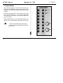
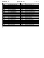
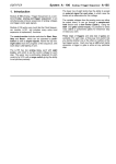
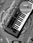
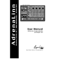
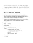
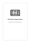
doepfer
System A - 100
CVM 16 A-192
1. Introduction
Module A-192 is a CV-to-MIDI interface that converts
16 control voltages in the range 0...+5V into 16 MIDI
control change messages. A-192 is the modular version of Pocket Control with the 16 rotary controls
replaced by 16 miniature jack sockets to process any
control voltage instead of the manually generated MIDI
control changes of Pocket Control.
MIDI messages appearing the MIDI Input are merged
to the MIDI controller messages generated by the
A-192.
128 different assignments (Presets) of the 16 CV
inputs to MIDI controller messages are available. Switching between the 128 presets takes place with an
8-pin DIP switch on the pc board (permanently) or via
incoming MIDI program change messages
(temporarily). If none of the 128 factory presets is
suitable new presets can be programmed with the
Pocket Control editor program which is available for
free on our web site www.doepfer.com.
The snapshot button transmits the 16 momentary
states of the 16 inputs as MIDI controller messages.
1
A-192 CVM 16
System A - 100
Controls and indicators
2. Overview
1 Snapshot : Momentary switch (sends a snapshot
of all the momentary CV settings)
A-192 CVM16
CV-to-MIDI Interface
1
2
3
4
!
2 Control:
9
Snapshot
1
Control
2
LED display
(- DIP switch: 8 pin switch on the A-192 pc board to
select a preset, not shown)
10
In- / Outputs:
11
12
5
13
6
14
7
15
8
16
DOEPFER
2
doepfer
MIDI
In
"
MIDI
Out
§
! Sockets :
16 CV inputs (range 0...+5V)
" MIDI In :
MIDI input
§ MIDI Out :
MIDI output
doepfer
System A - 100
3. Basics
Module A-192 converts up to 16 analog control voltages (CV) in the voltage range 0...+5V into 16 MIDI
controllers (exactly: MIDI control change messages).
The MIDI channel for each controller can be selected
(1-16). E.g. 16 different controllers on the same MIDI
channel may be chosen, or even the same controller
number on different MIDI channels. All mixtures of
controller numbers and MIDI channels are possible.
The term controller is not quite correct as A-192 even
supports similar messages like after touch or pitch
bend, as well as most of the common RPN resp.
NRPN controllers and most of the GS, XG controllers resp. XG sysex messages.
The active input voltage range is 0...+5V. Negative
voltages and voltages above +5V are not converted.
A protection circuit on each input prevents the damage of the module as long as the voltages applied to
the inputs are in the range of -12V...+12V. This
means that within the A-100 system it is not possible
to damage the A-192 module as the output voltages
of all A-100 modules are within these limits.
If negative voltages (e.g. from a LFO) or voltages
above +5V (e.g. from an ADSR) are to be converted
an attenuator / offset generator module (A-129/3) has
CVM 16 A-192
to be inserted between the voltage and the A-192
input. The A-129/3 enables the addition of a positive
voltage and the attenuation of the input voltage so
that the output (= input of A-192) is in the required
range of 0...+5V.
The assignments of the 16 CV inputs to MIDI controllers and channels is defined in 128 presets. A preset
is selected permanently with an 8-pin DIP switch on
the pc board or temporarily via incoming MIDI program change messages on the MIDI master channel.
You will find a table of all factory presets with the
corresponding DIP switch settings in the appendix of
this manual. If none of the factory presets is suitable
for your application you may program one or more
new presets with the editor program which is available for free on our web site www.doepfer.com.
(same as editor program for Pocket Control). The
program runs on a PC under Windows 95/98/2000.
For a small extra charge (about US$10.00) we also
have available the OEM version of Emagic’s Sounddiver (universal editor program) suitable for both PC
and Mac.
3
A-192 CVM 16
System A - 100
doepfer
As soon as one of the 16 input CVs changes the
corresponding MIDI controller messages is generated.
In case of a continually changing voltage (e.g. from a
LFO or Theremin) the corresponding MIDI controller is
transmitted permanently. In case of a static voltage
(e.g. from CV source A-176) the single transmission of
all 16 MIDI controllers can be triggered with the
snapshot button.
4. Controls and indicators
Unused inputs are connected to GND (= 0V) by means
of the switching contacts of the CV sockets (sockets
are “normalled to GND”). This means that an unused
input will generate no MIDI data as long as no plug is
inserted into the corresponding CV socket (and the
snapshot button is not operated). Please avoid to
connect a patch cord into a CV socket with the second
side left open. In this case the switching contact does
no longer connect the CV input to GND and random
MIDI data are generated for this CV input.
The switch is a remnant of Pocket Control which is
equipped with 16 (static) rotary potentiometers. The
switch is normally not required for A-192 operation.
Especially the snapshot function (item 1 in the list
above) is normally not necessary because the input
voltages of A-192 usually change permanenty and
thus the MIDI data are generated permanently.
The 16 analog inputs are internally converted into
digital data by means of an 8-bit analog-to-digital
converter (ADC). Because of the MIDI data format only
7 bits are used (MIDI data range 0...127).
4
1 Snapshot
The Snapshot switch has various functions:
• to send a Snapshot of all the current CV settings
• for setting the master MIDI channel
• to reset the A-192 after an overflow at the MIDI in
Generating a Snapshot:
The snapshot function is not achieved by just pressing
the snapshot switch, as this could be accidentally
pressed too easily. So to activate the Snapshot function, first briefly press the Snapshot switch once, this
causes the LED to flash, the Snapshot switch needs
to be pressed again within at least one second
(whilst the LED is still flashing). This then invokes the
snapshot function, and the data from all 16 control
knobs is transmitted from the A-192.
doepfer
System A - 100
The snapshot switch may even be used to set the MIDI
master channel. This is not as simple as for Pocket
Control because of the missing 16 potentiometers
(remember: the switch is a remnant of Pocket Control):
To set the Master channel, hold the snapshot switch
down for at least one second and keep it held down,
the LED then stays on to indicate Master channel
setting mode (do not let go of the button until the
required value has been selected). In this mode the
CV inputs become channel selectors, and do not
transmit the normal control data. To select a channel,
the input voltage change on one input is necessary
while the other 15 voltages remain unchanged (e.g. to
set channel 5, the voltage of CV input 5 has to be
changed). If you accidentally changed the wrong voltage, just change the correct one, as it is the last
voltage change that determines the actual Master
channel set.
In practice all plugs are removed except the one plug
that defines the MIDI master channel. On this plug now
a changing voltage has to appear.
The master channel is stored non-volatile in the module even during power off.
We know that this way of setting the master channel is
not very comfortable but this function is a remnant of
Pocket Control. In practice this step has to be carried
out only once and is not necessary if the editor program is used.
CVM 16 A-192
To clear any MIDI input error such as a MIDI overflow (too much data in one go), press the snapshot
switch briefly once (do not press it again until at least
one second has passed, or this would enter the snapshot mode). For details please refer to the next chapter.
2 Control
The LED 2 indicates the status in various modes.
Under normal operation the LED indicates MIDI input
activity, and also MIDI output activity when input
voltages are converted into MIDI data. The LED also
indicates:
• Power on reset - the LED will stay lit for around
one second when the power is first applied.
• Any error at the MIDI input (MIDI overflow) - the
LED turns on permanently
• Data and status when setting the Master channel
(see 1 snapshot)
• The status of the Snapshot function (see 1
snapshot)
• Indication that a preset has been changed
Typical reasons for a MIDI overflow are too much MIDI
data (e.g. MIDI output of a computer sequencer with
many active tracks/channels) or Sysex data sent too
fast to the module. In both cases wrong MIDI data may
be sent to the MIDI output of the module.
5
A-192 CVM 16
System A - 100
5. In- / Outputs
! CV Inputs 1 ... 16
The 16 sockets ! are the control voltage inputs of
the CV-to-MIDI interface. The control voltages to be
converted into MIDI data are connected to these sockets. The active voltage range for each input is
0...+5V. 0V corresponds to MIDI data 0, +5V to 127.
The conversion is linear (i.e. +2.5V corresponds to
about 63/64 MIDI data).
The module is working reliable as long as the input
voltages are within the limits 5V...+12V but only the
range 0...+5V is converted into MIDI data. Voltages
less than -5V may cause faulty MIDI data. The protection circuit on each input prevents a damage of the
module as long as the voltages applied to the inputs
are in the range of -12V...+12V. Voltages more than
+12V or less than -12V may damage the module.
Within the A-100 system it is not possible to damage
the module as no voltages beyond these limits are
generated within the A-100 system.
An attenuator/offset module A-129/3 should be used to
convert voltages beyond the range 0...+5V into the
active range 0...+5V.
6
doepfer
" MIDI In
The MIDI In socket " has 3 different functions:
• MIDI data from another MIDI device may be transmitted to the A-192 and merged with the MIDI data
generated by the A-192 (e.g. the MIDI output of a
keyboard).
• The MIDI input is required if an editor program is
used to change presets in the A-192 or to progam
new ones. Please refer to the manual of the editor
program for details. An editor program for PC is
available for free download on our web site
www.doepfer.com (same as Pocket Control editor).
• An incoming program change message on the
MIDI master channel selects one of the 128 presets. This selection is only temporarily, i.e. the new
preset is active only until the next power off. During
power on the preset defined by the DIP switch
setting is selected. The selection of a new preset
via program change is indicated by lighting up of
the LED for about one second. During this period
no incoming MIDI data is recognized (i.e. no MIDI
merging, no program change recognition).
If none of these applications is used the MIDI in socket
remains unconnected.
doepfer
System A - 100
§ MIDI Out
This is the MIDI Out socket. It is connected to the
MIDI input of the device controlled by the MIDI data of
the A-192 (e.g. computer sequencer, expander, keyboard, MIDI-toCV converter and so on).
6. User Examples
Module A-192 can be used to convert any control
voltage in the A-100 into MIDI controllers. Especially
those applications normally not available in the world
of MIDI are the most interesting ones. Of course one
may convert a (slowly oscillating) LFO or ADSR into
MIDI. But more interesting are e.g. those applications:
•
•
•
•
•
Theremin-to-MIDI (A-178 ➔ A-192)
Light-to-MIDI (A-179 ➔ A-192)
Envelope-to-MIDI (A-119 Envelope ➔ A-192)
Sequencer-to-MIDI (A-155 ➔ A-192)
Footcontroller-to-MIDI (A-177 ➔ A-192)
Vocoder MIDI interface
CVM 16 A-192
129/1 is connected to the A-192 inputs. The A-192
converts the 15 analysis voltages into 15 MIDI controllers. The 16th input may be used for voiced/unvoiced
control or as control voltage for the slew limiter.
The MIDI data generated by the A-192 may be recorded and stored with a computer sequencer. Dependent on the power of the sequencer different possibilities are coming up:
• Recording and playing back the recorded “vocoder
sequence” (MIDI controllers) at different at speeds
• “Freezing” at a certain position (e.g. a vowel like “a”)
• Storing certain vowels or filter settings
• Realtime display of the controllers like a spectrum
analyser
The conversion of the recorded MIDI controllers back
into control voltages may be performed with a special
version of the MIDI-to-CV converter A-191. A modified
version that responds to 16 MIDI controllers is required
(i.e. without LFO, after touch and pitch bend). The first
15 CV outputs are connected to the CV inputs of the
vocoder synthesis section A-129/2. The 16th CV output may be used for voiced/invoiced control (i.e. controlling a VC switch) or as control voltage for the slew
limiter controller A-129/4.
Another very important application of the A-192 is the
“MIDI-fication” of the vocoder modules A-129/x. For
this the outputs of the vocoder analysis module A7
A-192 CVM 16
System A - 100
7. Patch-Sheet
The following diagrams of the module can help you
recall your own Patches. They’re designed so that a
complete 19” rack of modules will fit onto an A4 sheet
of paper.
Photocopy this page, and cut out the pictures of this
and your other modules. You can then stick them
onto another piece of paper, and create a diagram of
your own system.
doepfer
A-192 CVM16
CV-to-MIDI Interface
1
9
Snapshot
2
10
Control
3
11
4
12
Make multiple copies of your composite diagram, and
use them for remembering good patches and set-ups.
5
13
P
6
14
7
15
8
16
• Draw in patchleads with colored pens.
• Draw or write control settings in the little
white circles.
DOEPFER
8
MIDI
In
MIDI
Out
doepfer
System A - 100
Appendix:
Selecting a Preset with the DIP switch
On the A-192 main board an DIP switch with 8 single
switches is located near the LED behind the sockets
no. 10 and 11. This switch is used to select one of the
128 presets after power on. As 8 switches could
address 256 presets the eighth switch is unused. Its
setting has no meaning so far.
The least significant switch (labelled “1” in the table on
the following page) is located below in direction to the
MIDI sockets. The most significant switch (labelled “8”
in the table) is located above near the LED.
A closed switch (position “ON”) corresponds to a “1” in
the table on the following page. An open switch
(position “OFF”) corresponds to “0”.
CVM 16 A-192
The term Masterchn means that the MIDI data are
transmitted on the MIDI master channel (see page 5
concerning the master channel).
More detailed information about the presets you may
find on our web site www.doepfer.com in the product
description and user’s manual of Pocket Control. In
this manual the presets are described a little bit more
detailed. A-192 is identical to Pocket Control if one
replaces the 16 rotary potentiometers (generating
0...+5V) by the 16 input sockets of A-192 in the
product description and user’s manual.
For the A-192 probably one of the more general presets 0...15 is the best choice. E.g. presets no. 8 (MIDI
controllers 0...15 on the master channel) or preset no.
9 (MIDI controllers 16...31 on the master channel).
The empty presets from no. 65 are not used while this
manual is written. But they may be in use when you
receive the module. On our web site www.doepfer.com
you will find the current state of all presets (same as
for Pocket Control).
Additionally a preset can be selected temporarily with
a MIDI program change message on the master channel (see chapter 5 / MIDI In).
9
A-192 CVM 16
12345678
00000000
10000000
01000000
11000000
00100000
10100000
01100000
11100000
00010000
10010000
01010000
11010000
00110000
10110000
01110000
11110000
00001000
10001000
01001000
11001000
00101000
10101000
01101000
11101000
00011000
10011000
01011000
11011000
00111000
10111000
01111000
11111000
10
System A - 100
Preset #: preset name
Preset 0: Volume Channel 1 - 16
Preset 1: Panorama Channel 1-16
Preset 2: Cutoff Channel 1-16
Preset 3: Resonance Chan. 1-16
Preset 4: Volume/Pan Ch.1 - 8
Preset 5: Volume/Pan Ch.9 - 16
Preset 6: Cutoff/Reson. Ch.1-8
Preset 7: Cutoff/Reson. Ch.9-16
Preset 8: Ctrl 0-15 Masterchn
Preset 9: Ctrl 16-31 Masterchn
Preset 10: Ctrl 32-47 Masterchn
Preset 11: Ctrl 48-63 Masterchn
Preset 12: Ctrl 64-79 Masterchn
Preset 13: Ctrl 80-95 Masterchn
Preset 14: Ctrl 96-111 Masterchn
Preset 15: Ctrl 112-127 Masterchn
Preset 16: GS/XG Masterchn
Preset 17: AWE/SB 1 Masterchn
Preset 18: AWE/SB 2 Masterchn
Preset 19: AWE/SB 3 Masterchn
Preset 20: AWE/SB 4 Masterchn
Preset 21: AWE/SB 5 Masterchn
Preset 22: GS/XG Drum Pitch
Preset 23: GS/XG Drum Level
Preset 24: GS/XG Drum Pan
Preset 25: GS/XG Drum Reverb
Preset 26: GS/XG Drum Chorus
Preset 27: GS/XG Drum Delay/Var
Preset 28: XG Drum Cutoff
Preset 29: XG Drum Reson.
Preset 30: XG Drum Attack
Preset 31: XG Drum Decay
12345678
00000100
10000100
01000100
11000100
00100100
10100100
01100100
11100100
00010100
10010100
01010100
11010100
00110100
10110100
01110100
11110100
00001100
10001100
01001100
11001100
00101100
10101100
01101100
11101100
00011100
10011100
01011100
11011100
00111100
10111100
01111100
11111100
doepfer
Preset #: preset name
Preset 32: XG Level Chn 1 - 16
Preset 33: XG Pan Chn 1 - 16
Preset 34: XG Reverb Chn 1 - 16
Preset 35: XG Chorus Chn 1 - 16
Preset 36: XG Dry Chn 1 - 16
Preset 37: XG Var Chn 1 - 16
Preset 38: XG Low EQ Gain Chn 1 - 16
Preset 39: XG Low EQ Chn 1 - 16
Preset 40: XG High EQ Gain Chn 1 - 16
Preset 41: XG High EQ Chn 1 - 16
Preset 42: XG Mpart-Effect Masterchn
Preset 43: XG Level AD1/2,W1-12
Preset 44: XG Pan AD1/2,W1-12
Preset 45: XG Reverb AD1/2,W1-12
Preset 46: XG Chorus AD1/2,W1-12
Preset 47: XG Var AD1/2,W1-12
Preset 48: XG Dry AD1/2,W1-12
Preset 49: XG EQ
Preset 50: XG Reverb
Preset 51: XG Chorus
Preset 52: XG Variation
Preset 53: XG Insertion 1
Preset 54: XG Insertion 2
Preset 55: GS Reverb/Chorus
Preset 56: Strings
Preset 57: Rebirth Mchn
Preset 58: CS1x Masterchn
Preset 59: Waldorf Pulse Mchn
Preset 60: ASR-X Masterchn
Preset 61: Doepfer MAQ 1 Mchn
Preset 62: Doepfer MAQ 2 Mchn
Preset 63: K5000 MCB10 Mchn