1
Installation manual
Washer-Dryer
WD4130, WD4240
Type WN3...
Installation manual in original language
438 9217-51/EN
2011.04.04
Contents
Contents
Safety precautions......................................................................................5
Technical data.............................................................................................7
Installation.................................................................................................11
Transportation and unpacking.............................................................11
Siting and floor.....................................................................................12
Mechanical installation.........................................................................13
Water connections...............................................................................14
Drain connection..................................................................................16
Evacuation system....................................................................................17
Fresh-air...............................................................................................17
Exhaust duct........................................................................................18
Exhaust dimensioning..........................................................................20
Air volume control................................................................................21
Connection of external liquid supplies.................................................25
Circuit diagram of function options for I/O module type 2...................29
Electrical installation.................................................................................37
Gas installation..........................................................................................41
Fasten the label....................................................................................42
Tables of pressure and adjustments WD4130.....................................43
Conversion instructions WD4130.........................................................44
Tables of pressure and adjustments WD4240.....................................45
Conversion instructions WD4240.........................................................46
Data label.............................................................................................48
Function checks........................................................................................49
The manufacturer reserves the right to make changes to design and
component specifications.
3
Safety Precautions
Safety Precautions
The machine is only intended for water-wash use.
Do not dry unwashed items in the machine
The machine is not to be used if industrial chemicals have been used for cleaning.
Do not allow minors to use the machine.
Do not hose down the machine with water.
The machine's door lock must under no circumstances be bypassed.
Items that have been soiled with substances such as cooking oil, acetone, alcohol,
petrol, kerosene, spot removers, turpentine, waxes and wax removers should be
washed in hot water with an extra amount of detergent before being dried in the
machine.
Items such as foam rubber (latex foam), shower caps, waterproof textiles, rubber
backed articles and clothes or pillows fitted with foam rubber pads should not be
dried in the machine.
Fabric softeners or similar products should be used as specified by the fabric
softener instructions.
The machine may not be used to dry floor mops that contain polypropylene.
The final part of a drying cycle occurs without heat (cool down cycle) to ensure that
the items are left at a temperature that ensures that the items will not be damaged.
WARNING. Never stop the machine before the end of the drying cycle unless all items
are quickly removed and spread out so that the heat is dissipiated.
Remove garments from the machine as soon as they are dried. This prevents them
from becoming creased and reduces the risk of spontaneous ignition.
If the machine develops a fault, this must be reported to the person in charge as soon
as possible. This is important both for your safety and that of others.
The machine must not be located where a door, sliding door, etc., can block the
machine's door
The machine is not intended to be used by people (including minors) with reduced
physical or mental capacity or lack of experience and knowledge. Such people must
be instructed in the use of the machine by a person who has responsibility fo their
safety. Minors must be supervised to ensure that they do not play with the machine.
Adequate ventilation has to be provided to avoid the back flow of gases into the room
for appliances burning other fuels, including open fires.
Gas heated:
If you can smell gas,
• Do not switch on any equipment
• Do not use electrical switches
• Do not use telephones in the building
• Evacuate the room, building or area
• Contact the person responsible for the machines
In order to prevent damage to the electronics (and other parts) that may occur as the
result of condensation, the machine should be placed in room temperature for 24 hours
before being used for the first time.
5
Technical data
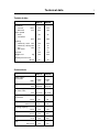
Technical data
WD4130
WD4240
Innerdrum
volume
diameter
litres mm 130
650
240
795
Drum speed
wash
extraction
rpm 49
42
980
890
Heating
electricity, wash kW electricity, drying kW gas
kW hot water
12.5
8
10
x
19.4
16
19
x
G-factor
350
350
kg 382
555
Sound pressure level
dB (A) 70
78
Weight, net
Connections
WD4130
Water valves
connection
BSP DN20
3/4"
WD4240
DN20
3/4"
Rec. water pressure
kPa 200-600
200-600
Functioning limits
for water valve
50-1000
Capacity
at 300 kPa
kPa 50-1000
l/min 20
60
Drain valve
outer Ø mm 75
75
Draining capacity
l/min 170
170
Evacuation
ø mm 125
200
m3/h 340
580
1/2
1/2
Air consumption
Gas
ISO 7/1-R 7
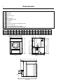
Technical data
8
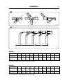
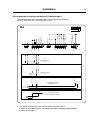
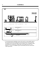
1
2
3
4
5
6
7
8
9
10
11
12
13
Electrical connection
Cold water
Hot water
Cold or hot water
Drain
Gas connection
Liquid detergent supply
Control panel
Soap box
Door opening, WD4130: ø395, WD4240: ø435
Exhaust connection
Fan inverter (adjustable speed setting)
Air inlet (option) WD4130 ø125, WD4240 ø160
WD4130
A
B
C
D
E
F
G
H
I
K
L
M
N
O
P
Q
910 1110 1330 435 1195 1055 90 1240 1095 105 275 385 410 535 585 450
WD4240 1020 1350 1450 500 1550 1170 95 1360 1215 105 265 440 430 650 710 535
A
9
8
3
13
G
4
2
7
1
10
Q
C
6
H
I
F
P
O
D
M
K
6625
N
Front
12
5
Rear side
B
11
12
6623
E
Left view
L
6624 B
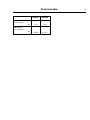
Technical data
WD4130
Frequency of the
dynamic force
Floor load at
max extraction
Hz WD4240
16.4
14.8
3.0±0.5
4.5±1.0
kN 9
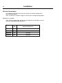
Installation
Installation
11
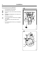
1
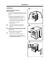
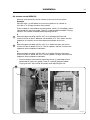
Transportation and unpacking,
WD4130, WD4240
The machine is delivered complete with expansion bolts etc. packed inside the machine in the
drum.
The machine is delivered bolted onto the
transport pallet and packed in a crate or box.
• Remove packing from the machine.
• Remove front and rear panel. Remove the bolts between the machine and pallet.
• Mount front and rear panel.
• Mount the feet.
1
• Place the machine on its final position.
• Level the machine with the feet of the
machine.
2
6682
2
The machine also comes with transport safety
devices (two plate angles between the support
and the drum).
In order to remove the safety devices:
3
• Remove the two side panels.
• Remove the two transport securities.
• The machine may not be moved with the
transport securities removed. Save the transport securities for future use.
6681
3
6683
Installation
12
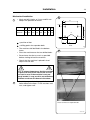
Siting and floor
Install the machine close to a floor drain or open
drain.
4
4
In order to make installation and servicing the
machine easier the following clearances are
recommended:
• At least 1000 mm between the machine and
the wall behind
• and min. 50 mm on both sides of the machine
whether installed next to the wall or other
machines.
6684
Installation
Mechanical installation
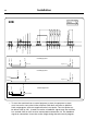
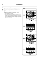
5
• Mark and drill 2 holes, ø 10 mm and 50 mm
deep in the positions X shown.
13
5
C
A
D
WD4130
WD4240
A
B
C
635 490 135
790 615 115
D
30
30
E
F
G
H
515 195 60 220
B
X
650 185 60 220
H
G
= position of feet
= drilling points for expander bolts
• The machine shall be lifted in the bottom
frame.
F
E
Front
5358
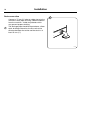
6
• Place the machine over the two drilled holes.
• Screw home the feet as much as possible
before starting to level the machine.
• Check that the machine is placed in level.
Adjust with the feet.
It is of utmost importance that the machine
is placed in level, from side to side as well
as front to rear. If the machine is not properly leveled, it may result in out-of-balance
without a real out of balance in the drum.
6
• Insert the expansion bolts supplied in the
holes drilled in the floor. Fit the washers and
nuts, and tighten well.
Knock out holes for expander bolts
2984, 2986
Installation
14
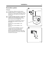
Water connections
All intake connections to the machine are to be fitted with manual shut-off
valves and filters, to facilitate installation and servicing.
Water pipes and hoses should be flushed clean before installation. After
installation hoses should hang in gentle arcs.
All connectors present on the machine must be connected up. The table shows the possible connection options, which will depend on the water
types to be connected to the machine. Check the machine plates too.
All water connectors must be connected up, otherwise the wash program will not function correctly.
Hoses are to be of an approved type and grade and comply with
IEC 61770.
Machines shall be connected with new water hoses. Re-used water hoses
must not be used.
The water pressure data is as follows:
• min:
50 kPa (0,4 kp/cm2)
• max:
1 MPa (10 kp/cm2)
• recommended: 200-600 kPa (2-6 kp/cm2)
If the water pressure is below the min. value, the wash result
can not be guaranteed for certain program.
Installation
1
2
cold and
7
hot
cold
hot
7
Water type Water connection
15
3
2
cold*/
hot
3
1
* For detergent container
5339 A
Installation
16
Drain connection
Connect a 75 mm (3") pipe or rubber hose to the
machine’s drain pipe, ensuring a downward flow
from the machine. Avoid sharp bends which
may prevent proper draining.
8
The drainage pipe should be located over a floor
drain, drainage channel or the like so that the
distance between the outlet and the drain is at
least 25 mm (1").
8
5330
Installation
Evacuation system
17
9
Fresh-air
9
10
For maximum efficiency and the shortest
possible drying time, it is important to ensure
that fresh air is able to enter the room from the
outside in the same volume as that blown out
of the room.
To avoid a draught in the room, it is advisable
to place the air inlet behind the machine.
The area* of the air inlet opening must be 5
times the size of the vent pipe area.
The resistance in the grating/slats on the air
inlet cover plate should not exceed 10 Pa
(0.1 mbar).
WD4130: The air consumption is max.
340 m3/h.
6685
WD4240: The air consumption is max.
580 m3/h.
*The area of the inlet opening is the area
through which the air can flow without
resistance from grating/slatted cover.
10
Note that gratings/slatted covers often block
half of the total fresh air vent area. Remember
to take this into account.
5xA
W00048
Installation
18
Exhaust duct
• The exhaust duct must be smooth on the inside (low air resistance).
• The exhaust duct must lead to the outdoors.
• The exhaust duct must lead clear of the building as condensation may
cause frost damage to the building.
• The exhaust duct must be protected against rain and foreign objects.
11
• The exhaust duct must have gentle bends.
• The exhaust duct must not be a shared duct between machinees and
appliances using gas or other fuels as their energy source.
When several machines share an exhaust duct:
12
• The exhaust duct diameter must increase after each machine.
The table below shows the exhaust duct diameter and the necessary
fresh-air inlet area.
NOTE!
It is recommended that each machine is connected to a separate
exhaust duct.
The evacuation pipe diameter must not be reduced.
Installation
19
11
W00049
12
W00052
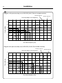
WD4130
No. of machines
1
2
3
4
5
6
7
8
9
10
Air outlet pipe
diameter in mm
125
160
200
200
250
250
315
315
315
315
Required area of
fresh-air inlet m2
0.04
0.08
0.12
0.16
0.20
0.24
0.28
0.32
0.36
0.40
Each machine requires a 200 x 200 mm fresh-air inlet opening.
WD4240
No. of machines
1
2
3
4
5
6
7
8
9
10
Air outlet pipe
diameter in mm
200
250
315
315
400
400
500
500
500
500
Required area of
fresh-air inlet m2
0.12
0.24
0.36
0.48
0.60
0.72
0.84
0.96
1.08
1.2
Each machine requires a 400 x 300 mm fresh-air inlet opening.
Installation
20
Exhaust dimensioning
It is important that the machine has the correct air volume compared to
each machines power.
If the air volume is smaller or larger this will result in a longer drying period.
Minimum air volume
If the outlet air volume gets too low the microprocessor will report an error
and error code E15 will be displayed.
Type
Power
kW
Recommended air flow range
(cold machine) m3/h
WD4130
8
290-310
WD4130
10
310-340
WD4240
16
510-540
WD4240
19
540-580
Installation
21
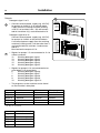
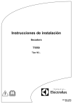
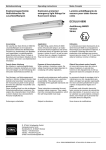
Air volume control WD4130
Remove cover panel for the fan inverter at the rear of the machine.
Example:
WD4130 with a 10 kW power must have an optimum air volume of
310-340 m3/h. (Empty machine and no heat).
Pressure drop is measured by removing temp. sensor (1) and adapt a hose
connected to a pressure gauge. There is a special program hidden "Drying
no heat" that can be activated when adjusting the fan.
13
A
Measured pressure drop 190 Pa at 57 Hz is between the lines and
shows that the air flow is between 310 and 340 m3/h. This shows that the
frequence is correctly set on the frequence controller for the fan.
14
B
Measured pressure drop 230 Pa at 51 Hz is above the lines and shows
that the air flow is below 310 m3/h. The fan speed is too low. Increase the
frequence on the frequence controller.
C
Measured pressure drop 160 Pa at 61 Hz is below the lines and shows
that the air flow is above 340 m3/h. The fan speed is to high. Decrease the
frequence on the frequence controller.
• Pressure drop is measured by removing sensor (1) and adapt a hose
connected to a pressure gauge. There is a special program hidden
"Drying no heat" that can be activated, when adjusting the fan.
13
1
2981, 2982
Installation
22
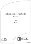
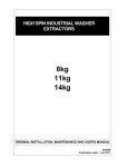
14
Diagram with pressure drop curve WD4130 (8 kW, Electric heated machine)
Air flow 290 m3/h
Air flow 310 m3/h
Pressure drop vs fan frequency
400
350
Pressure drop
300
250
B
200
A
C
150
100
50
0
44
46
48
50
52
54
56
58
60
62
64
66
fan motor frequency (Hz)
Diagram with pressure drop curve WD4130 (10 kW, Gas heated machine)
Air flow 310 m3/h
Pressure drop vs fan frequency
Air flow 340 m3/h
400
350
Pressure drop
300
250
B
200
A
150
C
100
50
0
44
46
48
50
52
54
56
58
fan motor frequency (Hz)
60
62
64
66
Installation
23
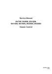
Air volume control WD4240
Remove cover panel for the fan inverter at the rear of the machine.
Example:
WD4240 with a 19 kW power must have an optimum air volume of
540-580 m3/h. (Empty machine and no heat).
Pressure drop is measured by removing temp. sensor (1) and adapt a hose
connected to a pressure gauge. There is a special program hidden "Drying
no heat" that can be activated when adjusting the fan.
15
A
Measured pressure drop 180 Pa at 57 Hz is between the lines and
shows that the air flow is between 510 and 540 m3/h. This shows that the
frequence is correctly set on the frequence controller for the fan.
16
B
Measured pressure drop 220 Pa at 49 Hz is above the lines and shows
that the air flow is below 510 m3/h. The fan speed is too low. Increase the
frequence on the frequence controller.
C
Measured pressure drop 140 Pa at 59 Hz is below the lines and shows
that the air flow is above 540 m3/h. The fan speed is to high. Decrease the
frequence on the frequence controller.
• Pressure drop is measured by removing sensor (1) and adapt a hose
connected to a pressure gauge. There is a special program hidden
"Drying no heat" that can be activated, when adjusting the fan.
15
1
2981, 2982
Installation
24
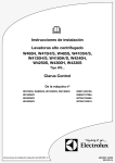
16
Diagram with pressure drop curve WD4240 (16 kW, Electric heated machine)
Air flow 510 m3/h
Air flow 540 m3/h
Pressure drop vs fan frequency
400
350
Pressure drop
300
250
B
200
A
150
C
100
50
0
44
46
48
50
52
54
56
58
60
62
64
66
fan motor frequency (Hz)
Diagram with pressure drop curve WD4240 (19 kW, Gas heated machine)
Air flow 540 m3/h
Air flow 580 m3/h
Pressure drop vs fan frequency
400
350
Pressure drop
300
250
B
200
A
150
C
100
50
0
44
46
48
50
52
54
56
58
fan motor frequency (Hz)
60
62
64
66
Installation
25
Connection of external liquid supplies
The external dosing equipment power supply must never be
connected to the machine’s incoming terminal block.
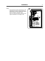
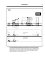
17
Detergent signal 1 to 5:
• Connect the external pump equipment for liquid washing detergent signal 1 to 5 to the I/O board, which is located to the right of the incoming
power supply.
The I/O card has edge connectors for connecting external pumps.
• Edge connectors on the I/O board can be loosened for connecting
cables.
17
6572
18
10
Liq. 10
9
Liq. 9
8
Liq. 8
7
Liq. 7
6
Liq. 6
5
0
4
Supply V
3
Common
2
Line
1
Neutral
18
Detergent signal 6 to 10:
• Connect the external pump equipment for liquid washing detergent
signal 6 to 10 to the terminal block located above the I/O board.
7026
Installation
26
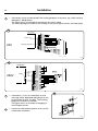
Outputs
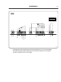
19
19
Detergent signal 1 to 5:
• Connect external power supply (e.g. 24V DC)
for pumps to 9 and 10. If an internal power
supply (from the washing machine) is being
used, it can be taken from 1 (N) and connected to 9 and from 2 (L) and connected to 10.
Detergent signal 6 to 10:
Connect external power supply (e.g. 24V DC)
for pumps to 3 and 4 on the terminal block.
If an internal power supply (from the washing
machine) is being used, it can be taken from 1
and connected to 3 and from 2 and connected to 4.
Max load on the outputs 0.5 A.
20
• Signals for pumps 1-5 are connected to 12-16
where connector:
12
Washing detergent signal 1
13
Washing detergent signal 2
14
Washing detergent signal 3
15
Washing detergent signal 4
16
Washing detergent signal 5
• Signals for pumps 6-10 are connected to terminal block 5-10 where block:
6
Washing detergent signal 6
7
Washing detergent signal 7
8
Washing detergent signal 8
9
Washing detergent signal 9
10
Washing detergent signal 10
• The programs on the machine can be found
on the machine’s data plate.
Signal 1
Signal 2
Signal 3
Signal 4
Signal 5
3M14*
–
Mainwash
Softener
Mop last rinse
Bleach
3R01*
Prewash
Mainwash
Softener
Pr 1 last rinse
Bleach
* M= Mop, R = Restaurant
Signal 6
Signal 7
Signal 8
Signal 9
Signal 10
5W05 (Woolmark)
–
Mainwash (Wet 2)
Last rinse (Wet 3)
–
–
Other programs
Prewash
Mainwash
Softener
Bleach
6634, 6635
Installation
Inputs
27
20
• The signal level can be 5-24V DC/AC or 100240V AC. For 5-24V, the signal reference is
connected to 3 and for 100-240V to 4. Potentials on the inputs cannot be mixed.
NB! The I/O board will be damaged if the voltage on connection 3 is too high, >24V.
6236
Installation
28
21
• Connection 8 may be connected if the washing program is to pause, e.g. while washing
detergent is being dosed.
The figure shows an example of engaging a 24V pause signal.
The washing program will pause for as long as the pause signal remains activated (high).
21
24V
6266
22
230V
6265
22
23
• Connection 7. If this is connected, an error
message will be displayed indicating that one
of the chemical tanks is empty. The washing
program will continue, however.
The figure shows an example of engaging a
normal open contact.
23
A
A
• Connect the liquid dosing hoses to any of the
connections marked A.
6577
Installation
29
Circuit diagram of function options for I/O module type 2
The wiring diagram for I/O module type 2 may be one of the following
variants: 22A, 22B, 22C, 22D, 22E, 22F or 22H.
22A
6606
• The signal received from external slot meters must be a pulse.
In order to count down prices, the signal initiating the programming procedure
must be active (high).
Installation
30
22B
6316
• To start the machine from a central payment system, the payment system
must transmit a start pulse to the machine. Door lock activates on positive
flank and program starts on negative flank of start pulse. The start pulse can
be either 230V or 24V. In order to receive a feedback signal once the machine
has started, 230V or 24V must be connected to connection 19. The feedback
signal on connection 18 remains active (high) during the entire wash program.
Installation
31
22C
6313
• The central payment or booking system shall transmit an active (high) signal to
the washing machine once permission has been granted to start the machine.
The signal must remain active (high) until the machine starts. A feedback signal
will be present on connection 18 and remain active (high) whilst the machine
door is closed but the wash program has not started. The feedback signal is
powered by 230V or 24V from connection 19.
Installation
32
22D
6314
• The figure shows standard function addressing for machines with the 3L41
program package.
• By maintaining an activated (high) signal on connection 5 ("Price red"), the
price of the wash program can be reduced. This function has a number of
uses, including providing reductions during a specific period of the day. Whilst
the signal remains active (high), the price of the wash program is reduced by
the percentage entered in the price programming menu.
Installation
33
22E
6315
• Heating pause: By connecting a signal to connection 6, you can pause operation of the machine whilst it heats up. The machine will pause for as long as
the pause signal remains active (high).
Installation
34
22F
5
6
1
2
1
2
3
4
5
RE101
Output 6 NO
Output 6 NC
RE102
RE103
Output 5
RE104
Output 4
Output 3
Output 2
Output 1
Input 4
Input 3
4
RE105
PTD5
3
6
Con 107
1
2
Con 115
2
Input 2
Input 1
RE106
1
Con 109
Con 110
Con 108
2
Com.
Com.
Con 111
1
+5V
2
2
F
Type of I/O card
Address
Function I/O:s
3
Start permitted
Central booking / payment
EBS / PCB / Camping
230V
Start permitted
Central booking / payment
EBS / PCB / Camping
24V
0V
Program run NO
Program run NC
Liquid det. sign 5
Liquid det. sign 4
Liquid det. sign 3
Liquid det. sign 2
Liquid det. sign 1
Common
Power for outputs
Common outputs
Temporary pause
Liq. det. empty
Heating pause
Blocking of start
Com. 24V(-)
Com. 100 -240V
Com. 24V(-)
Line
Neutral
Inp
+24V
M1
Start permitted
S1
M1
Central payment
Plexa Compact
S1
Status machine
6944
• The central payment or booking system shall transmit an active (high) signal to
the washing machine once permission has been granted to start the machine.
The signal must remain active (high) until the machine starts. A feedback signal
will be present on connection 18 and remain active (high) whilst the wash
program is running. The feedback signal is powered by 230V from connection
19 or external 24V.
Installation
35
22H
External power supply
7016
• Connect external power supply (e.g. 24V DC) for pumps to 3 and 4.
If an internal power supply (from the washing machine) is being used, it can be
taken from 1 and connected to 3 and from 2 and connected to 4.
Installation
Electrical installation
37
1
Electrical installation must be carried out
by an authorized personnel!
1NAC
Machines with frequency-controlled motors
can be incompatible with certain types of
earth leakage circuit breaker. It is important
to know that the machines are designed
to provide a high level of personal safety,
which is why items of external equipment
such as earth leakage circuit breakers
are not necessary. If you still want to connect your machine across an earth leakage
circuit breaker, please remember the following:
• contact a skilled, authorised installation company to ensure that the appropriate type of breaker is chosen and that the dimensioning is correct
• for maximum reliability, connect only one machine per earth leakage circuit breaker
• it is important that the earth wire is properly connected, including to the earth leakage circuit breaker.
5332
1AC
In instances where the machine is not equipped
with an omni-polar switch, one must be installed
beforehand.
5333A
Mount a multi-pole switch prior to the machine
to facilitate installation and service operations.
or
The connecting cable should hang in a gentle
curve.
Fuse size, see table.
When connecting to a terminal block, the connection cable shell must be stripped 10-11 mm.
The cable area must be at least 0.5 mm2 and no
more than 4 mm2 (AWG12/AWG20). The terminal block used is a spring loaded cage clamp.
1AC
Single-phase connection:
1
Connect the earth and other two wires as shown
in example in the figure.
6524
Installation
38
Three-phase connection:
2
Connect the earth, neutral and phase wires as
shown in example ”3AC” and ”3N AC” in the
figure.
When the installation is completed, check:
• that the drum is empty.
• that the machine operates by turning on the
mains switch, starting the machine and using
RAPID ADVANCE to reach the spin cycle (see
operations manual).
2
3AC
5333
or
3AC
6525
3N AC
5334
or
3N AC
6526
Installation
39
WD4130
Heating
alternative
Voltage
alternative
Total
kW
No
heating
200 V 3 AC
1.6
or
Gas
heating
208-240 V 1 AC
1.6
El
heating
200 V 3 AC
9.5
220-240 V 1 AC
12.5
208-240 V 3 AC
11.8
220-240 V 3 AC
12.5
380-415 V 3N/3 AC
12.5
415 V 3N AC
12.5
440/480 V 3 AC
13.5
380-415/220-240 V 3N/3
12.5
Fuse
A
10
10
35
63
35
35
20
25
20
20/35
WD4240
Heating
alternative
Voltage
alternative
Total
kW
No heating
200 V 3 AC
2.6
or Gas208-240 V 1 AC
2.6
heating
480 V 3 AC
2.6
El heating
200 V 3 AC
15.5
240 V 1 AC
14.3
220-230 V 3 AC
13.3
240 V 3 AC
14.3
208-240 V 3 AC
18.3
240 V 3 AC
20.9
380-400 V 3N/3 AC
13.3
380-400 V 3N/3 AC
19.4
415 V 3/3N AC
14.3
415 V 3N AC
20.9
440 V 3 AC
22.1
480 V 3 AC
23.9
380-400/220-230 V 3N/3
19.4
415/240 V 3N/3
20.9
415/240 V 3N/3/1
20.9/14.3
Fuse
A
16
16
10
50
63
50
50
63
63
35
35
35
35
35
35
35/63
35/63
35/63
Installation
41
Gas installation
To be carried out by qualified personnel
Mount a shut-off valve upstream from the
machine.
1
A
B
The gas connection to the machine should be
dimensioned to an output of 10 kW (WD4130)
and 19 kW (WD4240).
The factory nozzle pressure setting corresponds
to the fuel value given on the name plate.
C,D
Check that the nozzle pressure and fuel value
agree with the values given in the table. If not,
contact the supplier.
Bleed the pipe system before connecting the
dryer.
After connection, test all joints for leaks.
Test run
1
Loosen the measuring branch screw (B) 1/4 of a
turn.
Connect a manometer to the measuring branch
(B).
Select a programme that uses heat.
Start the machine.
Check the nozzle pressure, see table.
If necessary, adjust the setting screw (C) of the
regulator under the cover screw (D).
Check that the gas is burning evenly and with a
bluish flame.
Gas valve
A Measuring branch, supply pressure
B Measuring branch, nozzle pressure
C Cover screw
D Adjusting screw
7112B
Installation
42
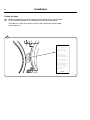
Fasten the label
Before installing the machine fasten the label “Read the user instructions”
on the inside of the door in a suitable place and at the front panel.
2
The label must have the correct country code, choose the correct label
from the gas kit.
2
GB, IE
Read the technical
instructions before
installing the appliance.
, IE
cal
GB
chni
e te fore
d th be iRea ctionse appl
ru
inst ling th
al
st
in .
ance
er
e us fore
d th be nce.
Rea ctions applia
ru
inst ing the
ay
light
em
ianc in a
appl alled
This be instroom te
ria
only if the prop
ap
roomts the quire the
re
meeilation ified inn
vent ts spec allatio
st
men nal in .
natiolations
.....
......
regu
No.
Art.
Read the user
instructions before
lighting the appliance.
This appliance may
only be installed in a
room if the room
meets the appropriate
ventilation requirements specified in the
national installation
regulations.
Art. No. ...........
7113
Installation
43
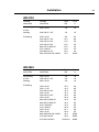
Table of pressure and adjustment WD4130
This gas appliance has been build to run on natural gas group I2H and I2E,
commonly identified by GNH. (Japan: LPG).
The data label shows the nozzle size and the nozzle pressure and the
countries that use this gas quality: AT,BG,CZ,DK,EE,FI,GR,HR,HU,IS,IE,IT,
LV, LT,NO,PT,RO,SK,SI,ES,SE,CH,TR,GB,and non-European countries.
Before connecting the appliance please make sure that the supplied gas
type is correct.
Following gas conversions are possible:
• Appliances to be installed to run on GNH or GNL in FR, BE: I2E+
• Appliances to be installed in NL, parts of DE: I2L, l2LL.
• Appliances to be installed to run on LPG in:
BE,CH,CY,CZ,ES,FR,GB,GR,IE,IT, LT,LU,LV,PT,SK,SI : l3+
• Appliances to be installed to run on LPG in: BE,CY,DK,EE,FR,GB,HU,IT,
LT,NL,NO,SE,SI,SK,RO, HR,TR,BG,IS,LU,MT and Non-European
countries: I3B/P (30 mbar) inlet pressure.
• Appliances to be installed to run on LPG in: PL: I3B/P (50 mbar) inlet pressure.
• Appliances to be installed to run on LPG in: AT,CH,DE,SK: I3B/P
(37 mbar) inlet pressure.
• Appliances to be installed to run on LPG in: FI,NL,RO and Non-Europe
an countries: I3P (30 mbar) inlet pressure.
• Appliances to be installed to run on LPG in: BE,CH,CZ,IE,IT,ES,FR,GR,GB,HR, LT,NL,: I3P (37 mbar) inlet pressure.
• Appliances to be installed to run on LPG in: AT,CH,DE,NL,LU,SK: I3P (50 mbar) inlet pressure.
WD4130 10 kW
Gas group
Nozzle size
ø mm (1)
Air reducing
plate
Inlet pressure (mbar)
Nozzle
pressure
(mbar)
Label no.
I2H, I2E
3.00
NO
20-25
8
DEFAULT
I2E+
2.30
NO
20/25
20/25
490375601
I2L, 12LL
3.00
NO
20-25
12
490375602
I3+
1.60
2xF
28-30/37
28-30/37
490375603
I3B/P
1.60
2xF
30, 37, 50
28
490375604
I3P
1.70
E
30, 37, 50
28
490375605
LPG Japan
1.60
2xF
28
28
DEFAULT
Installation
44
Conversion instructions WD4130
3
• Cut the power to the machine.
3
• Dismount the rear cover (A).
4
• Remove nozzle (B).
• Mount the enclosed nozzle (1).
8
5
A
• Replace/mount air reducing plate according
to table on previous page. All air reducing
plate types are shown.
• Loosen the measuring branch screw (C) 1/4
turn, connect a manometer to the measuring branch.
• Connect the power and select a programme
with heating.
7114
• Start the machine.
5
• See nozzle pressure in table on previous page
- set the nozzle pressure on setting screw (D)
under cover screw (E).
4
• Check that the gas flame burns evenly and
has a bluish colour.
5
B
• Mount the cover screw (E).
• Remount the rear cover.
NOTE!
After the conversion has been carried out, the
enclosed sign with the new gas type
printed on it must be affixed to the machine
data plate.
7115
5
C
D,E
7112A
Installation
45
Table of pressure and adjustment WD4240
This gas appliance has been build to run on natural gas group I2H and I2E,
commonly identified by GNH. (Japan: LPG).
The data label shows the nozzle size and the nozzle pressure and the
countries that use this gas quality: AT,BG,CZ,DK,EE,FI,GR,HR,HU,IS,IE,IT,
LV, LT,NO,PT,RO,SK,SI,ES,SE,CH,TR,GB,and non-European countries.
Before connecting the appliance please make sure that the supplied gas
type is correct.
Following gas conversions are possible:
• Appliances to be installed to run on GNH or GNL in FR, BE: I2E+
• Appliances to be installed in NL, parts of DE: I2L, l2LL.
• Appliances to be installed to run on LPG in:
BE,CH,CY,CZ,ES,FR,GB,GR,IE,IT, LT,LU,LV,PT,SK,SI : l3+
• Appliances to be installed to run on LPG in: BE,CY,DK,EE,FR,GB,HU,IT,
LT,NL,NO,SE,SI,SK,RO, HR,TR,BG,IS,LU,MT and Non-European
countries: I3B/P (30 mbar) inlet pressure.
• Appliances to be installed to run on LPG in: PL: I3B/P (50 mbar) inlet
pressure.
• Appliances to be installed to run on LPG in: AT,CH,DE,SK: I3B/P
(37 mbar) inlet pressure.
• Appliances to be installed to run on LPG in: FI,NL,RO and Non-European countries: I3P (30 mbar) inlet pressure.
• Appliances to be installed to run on LPG in:
BE,CH,CZ,IE,IT,ES,FR,GR,GB,HR, LT,NL,: I3P (37 mbar) inlet pressure.
• Appliances to be installed to run on LPG in: AT,CH,DE,NL,LU,SK: I3P
(50 mbar) inlet pressure.
WD4240 19 kW
Gas group
Nozzle size
ø mm (1)
Air reducing
plate
Inlet pressure (mbar)
Nozzle
pressure
(mbar)
Label no.
I2H, I2E
3.60
A+D
20-25
10
DEFAULT
I2E+
3.10
B+C
20/25
20/25
490375611
I2L, 12LL
3.60
A+D
20-25
15
490375612
I3+
2.20
D
28-30/37
28-30/37
490375613
I3B/P
2.20
D
30, 37, 50
28
490375614
I3P
2.30
D
30, 37, 50
28
490375615
LPG Japan
2.20
D
28
28
DEFAULT
Installation
46
Conversion instructions WD4240
6
• Cut the power to the machine.
3
• Dismount the rear cover (A).
6
• Remove the screw on the side of the locking plate x.
6
• Pull out the locking plate x, this releases the gas pipe.
X
• Remove the nozzle (1).
7
• Turn the pipe a little and mount the supplied gas nozzle.
• Push pipe with new nozzle back into its
place.
• Push locking plate all the way in and tighten the screw.
1
7116
7
2
4+3
7117
Installation
8
7
• Replace/mount air reducing plate according
to table on previous page. All air reducing
plate types are shown.
47
8
A
• Loosen the measuring branch screw (2) 1/4 turn; connect a manometer to the measuring branch (2).
• Connect the power and select a programme with heating.
C
• Start the machine.
7
• See nozzle pressure in table on previous
page - set the nozzle pressure on setting
screw (4) under cover screw (3).
• Check that the gas flame burns evenly and
has a bluish colour.
7
B
D
• Mount the cover screw (3).
• Mount the rear cover.
NOTE!
After the conversion has been carried out,
the enclosed sign with the new gas type
printed on it must be affixed to the dryer data
plate.
W00074, 75, 220, 221
E
F
Installation
48
Data label
When the machine is to be converted to another gas type, the data label at
the rear of the machine must be updated in order for the data to be correct.
9
Place the data label enclosed in the conversion kit on top of the data label
as shown below. If there are more than one data label, select the label with
the correct country code and gas type.
9
Product no.:
Serial no.:
OC:
Program:
Type:
WXXXXX
9868XXXXXX
09XXX / 99XXXXX
09XXXXXX
10XX
432XXXXXX,5XXX
432XXXXXXXX
WN3...WN3XXXX
Voltage:
WXXXXX
9868XXXXXX
09XXX / 99XXXXX
Date(YYMM): 10XX
09XXXXXX
X kg
WN3...WN3XXXX
50Hz
380 400V
3N
Rated Input:
1,6kW
Product no.:
Serial no.:
OC number:
Capacity:
Type/Model:
~
DK,NO,SE,FI,GB,ES,GR,IE,IT,PT,AT: 12H-20 MBAR
DE: 12E(LL)-20MBAR
ID.nr. 359BQ491
MANIF. PRESSURE : 10 MBAR. INJECTOR. Ø3,10 MM
NATURAL GAS: G20-20 MBAR
(INLET PRES: 20 MBAR, CAL. VAL. 37400 KJ/M3)
Art. No. ..........
10A
DK,NO,SE,FI,CH,CZ,EE,LT,SI,TR,BG,RO : I2H
GB,ES,GR,IE,IT,PT,AT,LV,HU,IS,SK : I2H
DE,PL,LU : I2E(LL)
PIN No 359BS703
MANIF. PRESSURE : 9 MBAR. INJECTOR: Ø2,58 MM
NATURAL GAS: G20
IP24D
(INLET PRES: 20 MBAR, CAL. VAL. 37400 KJ/M3)
For safety reasons use only genuine spare parts.
Made in Sweden
Electrolux Laundry Systems AB
341 80 Ljungby, Sweden.
Product no.:
Serial no.:
OC:
Program:
Type:
WXXXXX
9868XXXXXX
09XXX / 99XXXXX
09XXXXXX
10XX
432XXXXXX,5XXX
432XXXXXXXX
WN3...WN3XXXX
7110
Function checks
Function checks
49
1
Perform the following checks once the machine
is installed:
• Open the manual water valves.
• Open gas valve (if gas heated).
• Turn on the power to the machine.
• Put detergent into compartment 2 (Main
wash).
1
• Select a high temp. program with the control
knob (1).
2
• Press the knob.
1
Check:
• that the drum rotates normally and that there
are no unusual noises.
6217, 6179
2
• that there are no leaks in water supply/drain
connections.
• that water passes through the detergent
compartment and fabric conditioner compartment.
• that the door cannot be opened during a program.
• that the drying cycle is working.
6180
Electrolux Laundry Systems Sweden AB
341 80 Ljungby, Sweden
www.electrolux.com/laundrysystems
Share more of our thinking at www.electrolux.com