1
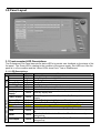
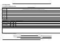
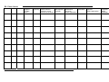
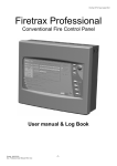
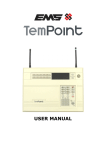
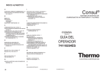
Firetrax Professional
Conventional Fire Control Panel
User manual & Log Book
Ventcroft Ltd
VFT-PFP 1/2/4/6/8Conventional Fire Alarm Control Panel User manual & Log Book
First Printed: 09/03/03
Document :???
Revision: 48.0.18
Last Revised : 12/4/03
Copyright © 2003 by Ventrcroft Ltd. All rights reserved. No part of this manual may be reproduced
or transmitted in any form or by any means, electronic or mechanical, including photocopying,
recording, or by any information storage or retrieval system, without prior written permission from
the publisher.
Notice of Liability
Every effort has been made to ensure that this manual / instructions contains accurate and current
information. However, Ventcroft Ltd shall not be liable for any loss or damage suffered by the
readers as a result of information held herein.
Trademarks.
Ventcroft and the Ventcroft logo / device are trademarks of Ventcroft Ltd.
All other trademarks are acknowledged as trademarks of their respective companies.
Ventcroft Ltd
Goddard Road
Astmoor Industrial Estate
Runcorn, Cheshire,
WA7 1NQ, United Kingdom
Tel: +44 (0)1928 581098
Fax: +44 (0)1028 581099
Email: [email protected]
Web: http://www.ventcroft.co.uk
If you have a questions about this product please do not hesitate to ring,
Technical Help: +44 (0)1928 581098
-3-
Table of Contents.
1.0 Overview: A Fire alarm system.....................................................................................................................................5
2.0 User Responsibilities ....................................................................................................................................................5
3.0 Panel Layout .................................................................................................................................................................8
3.1 Front mounted LED Descriptions ..............................................................................................................................8
3.1.1 LED Descriptions................................................................................................................................................8
3.2 External Controls.......................................................................................................................................................9
3.2.1 Button Descriptions ............................................................................................................................................9
4.0 Using the Fire Panel .....................................................................................................................................................9
4.1 General User (Access Level 1) .................................................................................................................................9
4.1.1 Led Lamp and panel buzzer test ........................................................................................................................9
4.1.2 Muting the panel’s internal buzzer......................................................................................................................9
4.1.3 Accessing Level 2.............................................................................................................................................10
4.2 Authorised User (Access Level 2)...........................................................................................................................10
4.2.1 Accessing Level 2 (keypad)..............................................................................................................................10
4.2.2 Accessing Level 2 (Keyswitch) .........................................................................................................................10
4.2.3 Exiting Access Level 2 (Keypad) ......................................................................................................................10
4.2.4 Exiting Access Level 2 (Keyswitch) ..................................................................................................................10
4.2.5 Silence/Activate Sounders................................................................................................................................10
4.2.6 Mute Panel Buzzer ...........................................................................................................................................11
4.2.7 Reset System ...................................................................................................................................................11
4.2.8 Disablements ....................................................................................................................................................11
4.2.9 Test Zones........................................................................................................................................................12
4.2.9.1 To place any zone into Test. .........................................................................................................................12
4.3 Led Flash Patterns (Yellow LED’s). ........................................................................................................................12
5.0 Fault Conditions ..........................................................................................................................................................13
5.1 Types of Fault..........................................................................................................................................................13
5.1.1 Zone Fault.........................................................................................................................................................13
5.1.2 Repeater Fault ..................................................................................................................................................13
5.1.3 Earth Fault ........................................................................................................................................................13
5.1.4 Alarm Fault .......................................................................................................................................................13
5.1.5 Fire Output Fault...............................................................................................................................................13
5.1.6 Aux Supply Fault ..............................................................................................................................................13
5.1.7 Power supply Fault ...........................................................................................................................................13
5.1.8 System Fault.....................................................................................................................................................14
5.2 In the Event of a Fault .............................................................................................................................................14
5.3 Fault Finding............................................................................................................................................................14
5.3.1 Fault Finding Chart ...........................................................................................................................................14
6.0 Appendix .....................................................................................................................................................................15
A1: System Configuration Data .................................................................................................................................15
B1: Fire Alarm Log Book ...........................................................................................................................................16
B2: Events other than false alarms or maintenance work .........................................................................................17
B3: False Alarms .......................................................................................................................................................18
B4: Maintenance Work ..............................................................................................................................................19
C1: Design Certificate................................................................................................................................................20
D1: Installation Certificate..........................................................................................................................................22
E1: Commissioning Certificate. .................................................................................................................................23
F1: Acceptance Certificate ........................................................................................................................................24
-4-
1.0 Overview: A Fire alarm system.
An automatic fire alarm system is typically made up of a fire alarm control panel, smoke detectors,
heat detectors, call points and audible warning devices; the purpose of this system is to provide
early warning of a developing fire so that people and animals can be evacuated and action can be
taken to stop the fire as soon as possible. However, a fire system does not assure protection
against property damage or loss of life resulting from a fire.
2.0 User Responsibilities
Section 7 of BS 5839-1:2002 Code of practice for system design, installation, commissioning and
maintenance, states that the owner or person having control of the premises should appoint a
single, named responsible person to supervise all matters pertaining to the fire alarm system. This
person should ensure that the system is tested and maintained in accordance with the
recommendations of BS 5839-1:2002, that appropriate records are kept and that the relevant
occupants in the protected premises are aware of their roles and responsibilities in connection with
the fire alarm system. It also needs to be the duty of the responsible person to ensure that
necessary steps are taken to avoid situations that are detrimental to the standard of protection
afforded by the system and to ensure that the level of false alarms is minimised.
Recommendations for the responsible person:
a) To supervise all matters pertaining to the fire alarm system, and should have sufficient
authority to carry out the duties listed below and should normally be the keeper of the
documentation regarding the fire alarm system.
b) Ensure the system is checked at least once every 24 hours to confirm that there are no
faults on the system.
c) Ensure that arrangements are in place for testing and maintenance of the system in
accordance with
BS 5839-1:2002 section 6
d) Ensure that the system log book is kept up to date and is available for inspection by any
authorised person.
e) Ensure that all relevant occupants of the protected premises are instructed in the proper use
of the system and are able to interpret fire, pre-alarm and fault indicators and they are
adequately familiar with the appropriate controls. It should also be ensured that the
occupants are aware of the measures necessary to avoid the generation of false alarms.
Relevant occupants should also be instructed in the facilities for disablement and the
circumstances in which they should and should not, be used. In premises in multiple
occupation, it should be ensured that sufficient representatives of each occupier are
instructed.
NOTE: Different levels of instruction might be necessary for different occupants
f) To ensure appropriate action is taken to reduce false alarms.
g) Ensure clear space around every fire detector (500mm) and manual call points remain
unobstructed.
h) Ensure communication between those responsible for building maintenance to ensure that
work does not unnecessarily compromise the protection afforded by the system, create
system faults or cause false alarms. If structural or occupancy changes occur or are
planned ensure that any necessary changes to the fire alarm system are considered at an
early stage.
i) Ensure drawings and operating instructions are up to date.
j) To ensure that the following spare parts are held within the premises:a. Six frangible elements and appropriate tools for manual call points, unless there are less
than 12 manual call points then only 2 frangible elements and tools need to be held.
b. Such other spare parts agreed between the user and the organisation responsible for
servicing the system.
-5-
Routine Tests.
Daily
• Check that the power led is lit (Green)
• Report any faults to the responsible person
Weekly test (You may wish to disable the Fire Output during some of these tests)
• Led lamp and internal buzzer test.
• A manual call point should be operated during normal working hours, confirm that the control
equipment is capable of processing a fire alarm signal and providing the correct outputs.
•
•
•
•
•
Note 1: It is essential that alarm receiving centre is contacted immediately before and immediately after the
test to ensure that unwanted alarms are avoided.
Note 2: The user needs to take into account manufacturer’s recommendations.
Weekly test should be carried out at approximately the same time each week; instructions to
occupants to report any instance of poor audibility of the fire alarm signal.
In premises in which some employees only work hours other than that at which the fire
alarm system is normally tested, an additional test(s) should be carried out at least once per
month to ensure familiarity of these employees with the fire alarm signal(s)
A different manual call point should be tested every week, so that all manual call points are
tested in rotation. The result of the weekly test and identity of the manual call point should
be recorded in the log book.
The duration for which any fire alarm signal is given at the time of the weekly test by the
user should not normally exceed one minute, so that, in the event of a fire at the time of the
weekly test, occupants will be warned by the prolonged operation of the fire alarm devices.
Voice alarm systems should be tested weekly in accordance with the recommendations of
BS 5839-9:2002
Recommendations for periodic Inspection and Test
The recommended period between successive inspection and servicing visits should not exceed
six months. If a risk assessment shows a need for more frequent inspection and servicing visits,
then all interested parties should agree the appropriate inspection and servicing schedule.
•
•
•
•
•
•
•
•
•
•
-6-
The system log should be examined. It should be ensured that any faults recorded have
received the appropriate action.
A visual inspection should be made to check whether structural or occupancy changes have
affected the compliance of the system.
False alarm records should be checked, and the rate of false alarms during the previous 12
months recorded. Action taken in respect to false alarms should be recorded.
Standby batteries should be disconnected and a full load alarm should be simulated.
Batteries and their connections should be examined and momentarily load tested (Other
than devices of a radio-linked system), to ensure that they are in good serviceable condition
and not likely to fail before the next service visit.
The fire alarm functions of the control and indicating equipment should be checked by the
operation of at least one detector or manual call point on each circuit. An entry should be
made in the log book indicating which initiating devices have been used for these tests.
The operation of the fire alarm devices should be checked.
All controls and visual indications at the control and indicating equipment should be checked
for correct operation.
The operation of any facility for automatic transmission of alarm signals to an alarm
receiving centre should be checked
All ancillary functions of the control and indication equipment should be tested.
•
•
•
•
•
All fault indicators and their circuits should be checked, where practicable, by simulation of
fault conditions.
All printers should be tested to ensure correct operation and characters are legible. It
should be ensured that all printer consumables are sufficient quantity or condition to ensure
that the printer can be expected to operate until the time of the next service visit.
Radio systems should be service in accordance with manufactures recommendations.
All further checks and tests recommended by the manufacturer of the control and indicating
equipment and other components of the system should be carried out.
On completion of the work, any outstanding defects should be reported to the responsible
person, the system log should be completed and a servicing certificate should be issued.
Recommendations for inspection and test of the system over a 12 month period
In addition to the work recommended above, it is recommended the following work be carried out
every year.
Note: The work described may be carried out over the course of two or more service visits
•
•
The switch mechanism of every manual call point should be tested, either by removal of a
frangible element, insertion of a test key or operation of the device as it would be operated in
the event of a fire.
All automatic detectors should be examined, as far as practicable, to ensure that they have
not been damaged, painted, or otherwise adversely affected. Therefore the detectors
should be functionally tested.
Note: The test should simulate the correct operation of the device, use of a test button or test magnet (for example)
does not satisfy the recommendation given.
•
•
•
•
•
•
•
•
In fire detection systems that enable analogue values to be determined at the control and
indicating equipment, it should be confirmed that each analogue value is within the range
specified by the manufacturer.
All fire alarm devices should be checked for correct operation. It should be confirmed that
visual fire alarm devices are not obstructed from view and their lenses are clean.
All unmonitored, permanently illuminated filament lamp indicators at control and indicating
equipment should be replaced.
Radio signal strengths in radio-linked systems should be checked for adequacy.
A visual inspection should be made to confirm that all readily accessible cable fixings are
secure and undamaged.
The cause and effect programme should be confirmed as being correct.
The standby power supply capacity should be checked to establish it remains suitable for
continued service.
All further annual checks and tests recommended by the manufacturer of the control and
indicating equipment and other components of the system should be carried out.
On completion of the work, any outstanding defects should be reported to the responsible person
and a record of the inspection and test should be made on the servicing certificate.
-7-
3.0 Panel Layout
3.1 Front mounted LED Descriptions
The Professional Fire Panel has various status LED’s to provide user feedback on the status of the
fire panel. The Green LED is relating to the condition of the power supply, Red LED’s so if the fire
panel is in a fire condition and the Yellow LED’s show Fault, Test or Disablement.
FAULT/TEST/DISABLED
FIRE
3.1.1 LED Descriptions
LED
Colour
Power
Green
Access
Yellow
Fire
Red
Zones(1-8)
Red
Fire Output
Red
General Fault
Yellow
Repeater
Yellow
Auxiliary
Yellow
Supply
Power Supply
Yellow
System Fault
Zones (1-8)
Test
Disabled
Yellow
Yellow
Yellow
Yellow
Earth
Yellow
Alarm
Yellow
Fire Output
Yellow
-8-
Description
Status of the power supply
Code Entry/ Access Level 2 Granted
Fire Detected on one of the zones
Zone in Fire
Fire Output operated
Fault Detected on one of the features below
Communication Lost with repeater panel, or in setup mode
Auxiliary supply fault
Power Supply fault, 24V, 16V, 13.8V, 5V, Battery or Mains
Supply
System Fault detected. System or Site data corrupt
Zone in Fault, Test or Disabled or currently being set-up
A zone has been put in Test or currently being set-up
A zone has been Disabled or currently being set-up
Earth fault has been detected or Disabled or currently being setup
Sounders fault detected or Sounders Disabled or currently
being set-up
Fire Output Fault detected or the Output Disabled or currently
being set-up
3.2 External Controls
There are several buttons which control the operation of the fire panel on the front of the fire panel
case. These controls are available from various levels: Level 1 or Level 2 (User Access)
3.2.1 Button Descriptions
Button
Description
Silence/Activate
Silence/ Activate the Sounders. (Level 2)
Sounders
Mute the internal buzzer in either fire or quiescent mode and in any
Mute Panel Buzzer
access level.
This key will reset the fire panel from either a fire or a fault condition.
Reset System
(Level 2)
Enter Disablements mode/Scroll through options/Code Entry
Disable/Next/1
Test Display or Enter Test mode/Toggle feature/Code Entry
Test/Toggle/2
Accept feature/Code Entry
Accept/3
Initiate Code entry/Exit out of Option/Code Entry
Code/Exit/4
Keyswitch to Enable Access Level 2 (Optional)
Keyswitch
4.0 Using the Fire Panel
There are two levels of access control on the Firetrax professional range of fire panels; these are
General user and Authorised User both of which have various functions available.
4.1 General User (Access Level 1)
Access level 1 is available to members of the general public, or persons having a general
responsibility for safety supervision, who might be expected to investigate and initially respond to a
fire alarm or a fault warning. Any fire, fault, test or disablements are clearly shown on the led
display (see 3.1.2)
The only control functions available at Access Level 1 are:• Led Lamp and panel buzzer test
• Muting the panel’s internal buzzer
• Accessing Level 2
4.1.1 Led Lamp and panel buzzer test
To test the panel’s Led display and the internal panel buzzer press the TEST/toggle/2 button, all of
the panel’s LED’s should illuminate and the internal buzzer should sound. If any of the LED’s fail to
light or the buzzer fails to sound please contact your maintenance company. (See 5.0 Fault
Finding)
4.1.2 Muting the panel’s internal buzzer
During a fire or fault condition the fire control panel’s internal buzzer will sound, this may be muted
by pressing the Mute Panel Buzzer button which will silence the internal buzzer. This buzzer will
resound upon the detection of another fire or fault condition.
-9-
4.1.3 Accessing Level 2
To gain access to the Authorised User controls (Access Level 2), press the Code/Exit/4 button until
the Access LED starts to flash you may then enter the user code to gain access to level 2 controls.
4.2 Authorised User (Access Level 2)
Access Level 2 is available only to authorised users of the fire control panel, who are responsible
for safety and who are trained to operate the control panel in the following conditions:a) Quiescent condition
b) Fire alarm condition
c) Fault warning condition
d) Disabled condition
An access code (or keyswitch if fitted) is required to gain access to level 2; this is to prevent
unauthorised changes to critical parts of the fire alarm system.
4.2.1 Accessing Level 2 (keypad)
To gain access to the Authorised User controls (Access Level 2), press the Code/Exit/4 button until
the Access LED starts to flash you may then enter the user code 2 1 4 3 the access led will then
constant indicating that level 2 access has been granted.
4.2.2 Accessing Level 2 (Keyswitch)
If the keyswitch option has been fitted you can gain access to level 2 by inserting and turning the
keyswitch a quarter turn clockwise. The access led should go constant to indicate level 2 access is
granted.
4.2.3 Exiting Access Level 2 (Keypad)
To exit Level 2, you can press the Code/Exit/4 button at any time to exit out of the function that you
are currently in and then finally out of Access Level 2 completely.
4.2.4 Exiting Access Level 2 (Keyswitch)
Turn the keyswitch a quarter turn anti-clockwise at anytime to exit out of user access level 2.
4.2.5 Silence/Activate Sounders
This button can be used to toggle the sounder outputs from Off to On and vice versa.
4.2.5.1 During Quiescent Condition.
Pressing the Silence/Activate Sounders button will cause the alarm sounders to sound;
this will not cause the fire output to operate. Pressing the Silence/Activate Sounders
button again will cause the alarm sounders to silence. This option can be used for fire drill’s
or testing the sounders.
NOTE: If the sounders have been disabled (See 4.2.8) pressing this button will have no
affect.
- 10 -
4.2.5.2 During Fire Condition.
In a fire condition the alarm sounders may be silenced by pressing the Silence/Activate
Sounders button. The fire output will remain regardless of the condition of the alarm
outputs. Upon the detection of any subsequent fire conditions the alarms sounders will
resound.
4.2.6 Mute Panel Buzzer
During a fire or fault condition the fire control panel’s internal buzzer will sound, this may be muted
by pressing the Mute Panel Buzzer button which will silence the internal buzzer. This buzzer will
resound upon the detection of another fire or fault condition.
4.2.7 Reset System
Once the cause of a fire or fault condition had been investigated and cleared and the alarm
sounders have been silenced (During a fire condition) the fire control panel may be reset by
pressing the Reset System button. This will cause the system to be reset; all the Led’s will
illuminate and the panel buzzer will sound, after a few seconds the system will restart.
NOTE: If there are still any zones in fire or fault condition or any outputs still in fault the panel will
go back into the alarm state as before the system reset.
4.2.8 Disablements
Zones and certain control panel functions can be temporarily disabled; this may be due to routine
test on the system or if conditions in certain areas may cause false alarms.
The following features and functions may be disabled:Function
Zones
Earth
Alarm
Fire Output
Action taken by fire panel.
Fire and Fault conditions will not be processed
Earth faults will be ignored.
Alarm sounders will not activate in any condition
Fire conditions will not be transmitted to external
equipment
4.2.8.1 To Disable or re-enable any of the above functions
• Press and hold the Disable/Next/1 button until the Disablement Led lights.
• Release the button. Zone 1 Fault Led will flash. (See 4.3 Led flash patterns)
• Press the Disable/Next/1 button to scroll to the next available zone or feature.
• Press the Test/Toggle/2 button to toggle the state of the Zone/feature as required
(Disabled/Enabled).
• Once the correct state for the feature is selected press the Accept/3 button to confirm the
selection.
• Press the Disable/Next/1 button to scroll through the rest of the zones/features that can be
enabled/disabled, using the Test/Toggle/2 and Accept/3 buttons were necessary to
enable/disable zones or features.
• Repeat this procedure until all required zones/features are enabled/disabled.
• To return to access level 1 press the Code/Exit/4 button, turn the keyswitch anticlockwise or
press the Panel Reset button.
Note: Once in access level 2 you may enter the Disablements option at anytime by pressing and
holding the Disable/Next/1 button until the disablement LED is lit.
- 11 -
4.2.9 Test Zones
Zones may be placed in a test mode in order to perform routine maintenance or to aid
commissioning. This converts the zone to non-latching “One man walk test” mode.
Note: It is recommended that on an already installed and commissioned fire alarm system that only
one zone be put in test mode at any one time.
• During this mode when a smoke detector or manual call point is activated the alarm
sounders will sound an activated signal (1 second ring).
• The system will then try to reset the zone.
• if the alarm condition is removed (i.e. the smoke detector’s chamber clears of test smoke or
the manual call point is reset) then the system alarms will sound an all clear signal (2 one
second rings with a one second gap between on the alarm sounders.)
• You may then continue to test further detectors or manual call points in that zone or on other
zones in test.
• If when the system resets the activated test zone and the fire condition continues the system
will try to reset the zone a further five times; if the alarm signal is not removed from the zone
the panel will then sound a fault signal (5 one second rings with a one second gap in
between.)
• The fire panel will continue to try to reset the zone in test; if the zone is still in a fire condition
it will continue to give the fault signal.
• If the fault cannot be rectified the zone must be disabled (see 4.2.8) before you can continue
to test any further zones in test mode.
4.2.9.1 To place any zone into Test.
• Press and hold the Test/Toggle/2 button until the test Led lights.
• Release the button. Zone 1 Fault Led will flash. (See 4.3 Led flash patterns)
• Press the Disable/Next/1 button to scroll to the next available zone or feature or
• Press the Test/Toggle/2 button to toggle the state of Zone 1 as required (Disabled/Enabled).
• Once the correct state for the feature is selected press the Accept/3 button to confirm the
selection.
• Press the Disable/Next/1 button to scroll through the available features that can be disabled,
using the Test/Toggle/2 and Accept/3 buttons were necessary to enable/disable zones or
features.
• Repeat this procedure until all zones/features are enabled/disabled.
• To return to access level 1 press the Code/Exit/4 button, turn the keyswitch anticlockwise or
press the Panel Reset button.
Note: Once in access level 2 you may enter the Test option at anytime by pressing and holding the
Test/Toggle/2 button until the test LED is lit.
4.3 Led Flash Patterns (Yellow LED’s).
Flash
Type
OFF
ON
Flash
Slow
Flash
Fast
Flash
- 12 -
Description
OFF
ON
1 ON / 1 OFF
7 ON / 1 OFF
1 ON / 7 OFF
Result
Feature/Zone enabled
Feature/Zone Disabled
FAULT Detected.
Cursor position. This flash pattern shows that the feature under the
cursor is enabled.
Cursor position. This flash pattern shows that the feature under the
cursor is disabled.
5.0 Fault Conditions
When the system detects a fault condition, both the General Fault LED and the detected fault LED
will flash and the internal buzzer will sound. The internal buzzer can be muted at either access
level (1 or 2) by pressing the mute panel buzzer button (see 4.1.2 or 4.2.6)
5.1 Types of Fault
The fire alarm control panel can detect and report several different type of fault as described
below:5.1.1 Zone Fault
When the system detects a wiring problem either an open/short circuit or if a detector head has
been removed from its base; the corresponding zone fault led will flash.
Note: Dependant upon the fault and the type of system installation, alarms raised upon a faulty
zone my not be recognised on the fire alarm panel until the fault is resolved.
5.1.2 Repeater Fault
If the connection between the fire control panel and one or more of the repeater panels is lost or
fails will cause the repeater LED to flash.
Note: Dependant upon the fault and the type of system installation some or all of the repeaters
may no longer operate correctly.
5.1.3 Earth Fault
This fault will occur when a connection is made between earth and one of the transmission paths to
the fire control panel.
5.1.4 Alarm Fault
When the fire control panel detects a wiring fault or sounder short on either of the sounder circuits
during quiescent or alarm condition will cause the alarm fault LED to flash.
Note: Dependant upon the fault and the type of system installation some or all of the fire alarm
sounders fail to operate during an alarm condition.
5.1.5 Fire Output Fault
This Led illuminates when either an open or short circuit is detected on the Fire Output cabling or
devices connected to the terminals.
5.1.6 Aux Supply Fault
This Led illuminates when either too much current is drawn or the auxiliary supply is shorted out.
5.1.7 Power supply Fault
The Power supply fault Led illuminates when there is a fault on the battery charge circuit, 24/28V
supply,16V supply, 13.8V supply, or the 5v supply or when the battery or mains is removed.
- 13 -
5.1.8 System Fault
The system fault illuminates when there is one of the following faults: - Watchdog timeout, Site or
program memory has become corrupted, or there is a fault on the fire control panel circuit board.
5.2 In the Event of a Fault
•
•
•
Mute the panel’s internal buzzer by pressing the mute panel buzzer (see 4.1.2 or 4.2.6),
this may be done from either access level 1 or 2.
Record the fault(s) in the Log Book (see Appendix B3: Log Book-False Alarms) and
take appropriate action to correct the fault(s).
Reset the system. If all the faults are cleared the general fault and the fault condition will
be cleared, if the fault has not been cleared both the general fault LED and the fault
condition LED will reappear as before and the above process will have to be repeated.
5.3 Fault Finding
When a fault is detected there are several simple tests that the responsible person can carry out to
resolve the fault before calling the maintenance company.
5.3.1 Fault Finding Chart
Fault Indication
Zone Fault
Repeater Fault
Earth Fault
Alarm Fault
Fire Output
Fault
Aux Supply
Fault
Power Supply
Fault
System Fault
- 14 -
Possible Cause
• Detector head removed
• Cable Open/Short circuit
• EOL Device missing
• Damaged Cable
• Bad connection
• Faulty Repeater
• Damaged Cable
• Bad connection
• Damaged Cable
• Bad connection
• EOL Device missing
• Too many devices on circuit
• Damaged Cable
• Bad connection
• EOL Device missing
• Too many devices on circuit
• Damaged Cable
• Bad connection
• Too many devices on circuit
• Mains Supply Failure
• Back-up Battery Failure
• Internal Control panel failure.
• Electrical Interference
• Corrupt system memory
Corrective Action
Check the zone looking for any detector
heads that have been removed or incorrectly
fitted, Refit or reseat the detector head.
Check for any damage on the cable run.
Call the maintenance company.
Check for any damage on the cable run.
Call the maintenance company.
Check for any damage on the cable run.
Call the maintenance company.
Check for any damage on the cable run.
Call the maintenance company.
Check for any damage on the cable run.
Call the maintenance company.
Check for any damage on the cable run.
Call the maintenance company.
Check incoming mains supply.
Check isolating fuse
Call maintenance company
Reset Fire Control System
Reprogram Site configuration
Call maintenance company
6.0 Appendix
A1: System Configuration Data
Fire Zone Information
Zone Description
A concise explanation of areas and rooms contained in each zone
Zone
Number
1
2
3
4
5
6
7
8
Fire Panel Input/Output Routing Information
Type Of Input
Class Change
Type Of Output
Fire Output
Relay Output
Connected?
Yes
No
Connected?
Yes
Yes
How is it connected?
What Happens When Activated?
No
No
Additional Information
Any additional information the user needs to know should be entered here; Repeater locations, additional outputs routing information, etc.
The information above was completed by:
Name (in block letters):
Signature:
For and on behalf of:
- 15 -
Position:
Date:
B1: Fire Alarm Log Book
Foreword
It is recommended that this log book be maintained by a responsible person, who should ensure that every entry is
properly recorded. This is necessary to satisfy the recommendations of BS5839-11), compliance with which may be a
requirement of legislation. If your premises are certificated under the Fire Precautions Act 1971, failure to keep a
suitable log book may be a breach of the requirements of the certificate, which is a criminal offence.
•
•
•
•
•
•
•
•
•
•
The following must be recorded:The name of the responsible person.
Brief Details of the maintenance arrangements.
Dates and times of all tests, including fire drills.
Dates and times of all fires to which the system responds.
Dates and times of all false alarms.
Causes, circumstances surrounding, and category, of all false alarms (if known).
The identity of any manual call point or automatic fire detector that triggers any of the above fire alarm signals
(if known).
Dates, times and types of all faults and defects.
Dates and types of all maintenance (e.g. service visit or non-routine attention).
Site Data
Address of protected premises:
Company:
Address 1:
Address 2:
Address 3:
City:
Post Code:
Responsible person:
The System was designed by:
The system was installed by:
The system was commissioned by:
The system was accepted by:
Verification was undertaken by:
The system is maintained under contract by:
until:
,
who should be contacted if maintenance is required.
Telephone number:
,normal hours (Mon to Fri).
Manned Centre telephone number:
,outside normal hours.
, Manned Centre Code:
Normal maximum attendance time for a maintenance technician is:
Expendable component replacement periods (list):
Component:
1)
Replacement Period:
BS 5839-1:2002 Fire detection and alarm systems for buildings – Code of practice for system design, installation,
commissioning and maintenance.
- 16 -
B2: Events other than false alarms or maintenance work
Date
- 17 -
Time
Event (e.g. test, fire alarm signal, fault)
Zone
(where applicable)
Device
(where applicable)
Action Required
(where applicable)
Date completed
(where applicable)
Initials
B3: False Alarms
Date
- 18 -
Time
Zone
Device that
triggered
the alarm
signal
Cause
(if known)
Brief circumstances
(where cause in
unknown, record
activities in the area)
Maintenance
Visit required
(Yes/No)
Findings of
Maintenance
technician
(where applicable)
Category of
false alarm
Further action
required
(where applicable)
Action
completed
(where
applicable)
B4: Maintenance Work
Date
- 19 -
Time
Zone
(where applicable)
Device
(where applicable)
Reason for work
Work carried out
Further work
required
Signature
C1: Design Certificate
Certificate of design for the fire alarm system at:
Company:
Address:
:
:
City:
Post Code:
I/we being the competent person(s) responsible (as indicated by my/our signatures below) for the design of the fire
alarm system, particulars of which are set out below, CERTIFY that the said design for which I/we have been
responsible complies to the best of my/our knowledge and belief with the recommendations of Section 2 of
BS 5839-1:2002 for the system Category described below, except for the variations, if any, stated in this certificate.
Name (in block letters):
Signature:
Position:
Date:
For and on behalf of:
Address:
Postcode:
The extent of liability of the signatory is limited to the system below.
System Category (see BS 5839-1, Clause 5):
Variations from the recommendations of Section 2 of BS 5839-1 (see BS 5839-1, Clause 7):
Extent of system covered by this certificate:
Brief description of areas protected (not applicable for Category M, L1 or P1 systems):
- 20 -
Measures incorporated to limit false alarms. Account has been taken of the guidance contained in Section 3 of BS
5839-1:2002 and, more specifically (tick as appropriate):
The system is manual. Type and siting of manual call points takes account of the guidance contained in
Section 3 of BS 5839-1.
The system incorporates automatic fire detectors and account has been taken of reasonably foreseeable
causes of unwanted alarms, particularly in the selection and siting of detectors.
An appropriate analogue system has been specified.
An appropriate multi-sensor system has been specified.
A time-related system has been specified. Details:
Fire signals from automatic detectors initially in a staff alarm, which delays a general alarm/transmission of
signals to an alarm receiving centre (delete as applicable) for
min.
Appropriate guidance has been provided for the user to enable limitation of false alarms.
Other measures as follows:
Installation and commissioning
It is strongly recommended that installation and commissioning be undertaken in accordance with the
recommendations of Section 4 and Section 5 of BS 5839-1:2002 respectively.
Soak test
In accordance with the recommendations of 35.2.6 of BS 5839-1:2002, it is recommended that, following
commissioning, a soak period of
should follow.
(Enter a period of not less than one week.)
As the system incorporates no more than 50 automatic fire detectors, no soak test is necessary to satisfy
the recommendations of BS 5839-1:2002
Verification
Verification that the system complies with BS 5839-1:2002 should be carries out, on completion, in accordance with
clause 43 BS 5839-1:2002:
Yes
No
To be decided by the purchaser or user
Maintenance
It is strongly recommended that, after completion, the system is maintained in accordance with Section 6 of
BS 5839-1:2002.
User Responsibilities
The user should appoint a responsible person to supervise all matters pertaining to the fire alarm system in
accordance with the recommendations of Section 7 of BS 5839-1:2002
- 21 -
D1: Installation Certificate
Certificate of installation for the fire alarm system at:
Company:
Address:
:
:
City:
Post Code:
I/we being the competent person(s) responsible (as indicated by my/our signatures below) for the installation of the fire
alarm system, particulars of which are set out below, CERTIFY that the said installation for which I/we have been
responsible complies to the best of my/our knowledge and belief with the specification described below and with the
recommendations of Section 4 of BS 5839-1:2002, except for the variations, if any, stated in this certificate.
Name (in block letters):
Signature:
Position:
Date:
For and on behalf of:
Postcode:
The extent of installation work covered by this certificate
Specification against which system was installed:
Variations from the specification and/or Section 4 of BS 5839-1 (see BS 5839-1, Clause 7):
Wiring has been tested in accordance with the recommendations of Clause 38 of BS 5839-1:2002.
Test results have been recorded and provided to:
Unless supplied by others, the “as fitted” drawings have been supplied to the person responsible for commissioning the
system (see 36.2 of BS 5839-1:2002).
- 22 -
E1: Commissioning Certificate.
Certificate of commissioning for the fire alarm system at:
Company:
Address:
:
:
City:
Post Code:
I/we being the competent person(s) responsible (as indicated by my/our signatures below) for the commissioning of the
fire alarm system, particulars of which are set out below, CERTIFY that the said work for which I/we have been
responsible complies to the best of my/our knowledge and belief with the recommendations of Clause 39 of
BS 5839-1:2002, except for the variations, if any, stated in this certificate.
Name (in block letters):
Position:
Signature:
Date:
For and on behalf of:
Postcode:
The extent of liability of the signatory is limited to the systems described below.
Extent of system covered by this certificate
Variations from the recommendations of Clause 39 of BS 5839-1:2002 (see BS 5839-1, Clause 7):
All equipment operates correctly.
Installation work is, as far as can reasonably be ascertained, of an acceptable standard.
The entire system has been inspected and tested in accordance with the recommendations of 39.2c of BS
5839-1:2002.
The system performs as required by the specification prepared by:
A copy of which I/we have been given.
Taking into account the guidance contained in Section 3 of BS 5839-1:2002, I/we have not identified any
obvious potential for an unacceptable rate of false alarms.
This documentation described in clause 40 of BS 5839-1:2002 has been provided to the user.
The following work should be completed before/after (delete as applicable) the system becomes operational:
The following potential causes of false alarms should be considered at the time of the next service visit:
Before the system becomes operational, it should be soak tested in accordance with the recommendations of 35.2.6 of
BS 5839-1:2002 for a period of:
(Enter a period of either one week, such period as required by the
specification, or such period as recommended by the signatory to this certificate, whichever is the greatest, or delete if
not applicable.)
- 23 -
F1: Acceptance Certificate
Certificate of acceptance for the fire alarm system at:
Company:
Address:
:
:
City:
Post Code:
I/we being the competent person(s) responsible (as indicated by my/our signatures below) for the acceptance of the
fire alarm system, particulars of which are set out below, ACCEPT the system on behalf of:
Name (in block letters):
Signature:
Position:
Date:
For and on behalf of:
Postcode:
The extent of liability of the signatory is limited to the system below.
Extent of the system covered by this certificate
All installation work appears to be satisfactory.
The system is capable of giving a fire alarm signal.
The facility for remote transmission of alarms to an alarm receiving centre operates correctly.
(Delete if not applicable.)
The following documents have been provided to the purchaser or user:
‘As fitted’ drawings.
Operating and maintenance instructions
Certificates of design, installation and commissioning.
A log book.
Sufficient representatives of the user have been properly instructed in the use of the system, including, at
least, all means of triggering fire signals, silencing and resetting the system and avoidance of false
alarms.
All relevant tests, defined in the purchasing specification, have been witnessed.
(Delete if not applicable.)
The following work is required before the system can be accepted:
- 24 -