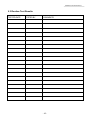
1
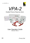
www.ventcroft.co.uk
Disabled Persons Response Alarm.
User Operation Guide
Document: VI49.2
…Protecting People
Meditell 2 User Manual VI49.2
Ventcroft Ltd
Meditell-2 Disabled Person Response (WC) User Guide
First Printed: 19/07/05
Document: 49
Revision: 2
Last Revised: 09/08/05
Trademarks.
Ventcroft and the Ventcroft logo / device are trademarks of Ventcroft Ltd
All other trademarks are acknowledged as trademarks of their respective companies.
Notice of Liability
Every effort has been made to ensure that this manual / instructions contains
accurate and current information. However, Ventcroft Ltd shall not be liable
for any loss or damage suffered by the readers as a result of information held
herein.
Ventcroft Ltd
Goddard Road
Astmoor Industrial Estate
Runcorn, Cheshire,
WA7 1NQ, United Kingdom
Tel: +44 (0)1928 581098
Fax: +44 (0)1928 581099
Email: [email protected]
Web: www.ventcroft.co.uk
-2-
Meditell 2 User Manual VI49.2
Table of Contents
1.0 Description............................................................................................................... 4
2.0 Operating Modes..................................................................................................... 5
2.1 Normal Stand-By Mode – Mains On (Quiescent) ......................................................................... 5
2.2 Battery back Up Mode - Mains off. ............................................................................................... 5
2.3 Battery Saver Power Off................................................................................................................ 5
3.0 Indicators and Sounders ........................................................................................6
3.1
3.2
3.3
3.4
3.5
ECU Green Power LED................................................................................................................ 6
ECU Amber Fault LED ................................................................................................................ 6
ECU Red Call LED....................................................................................................................... 6
ECU Internal Buzzer..................................................................................................................... 6
Field Warning Devices ................................................................................................................. 6
4.0 Operation................................................................................................................. 7
4.1 Generate a Call Alarm Using a Ceiling Pull Cord Device............................................................. 7
4.2 Mute a Call Alarm at the ECU....................................................................................................... 7
4.3 Reset a Call Alarm using a “Remote Reset Device” ..................................................................... 7
4.4 Reset a Call Alarm using ECU ...................................................................................................... 7
4.5 System Test/Reset.......................................................................................................................... 7
4.6 To Generate an “Priority Call” from “stand by mode”.................................................................. 8
4.7 To Generate an “Priority Call” while a “Standard Call” is in progress ......................................... 8
4.8 Reset a “Priority Call” using a “Remote Master Reset Device”.................................................... 8
4.9 Reset a “Standard Call” using a “Remote Master Reset Device”.................................................. 8
5.0 Routine Testing and Maintenance. ....................................................................... 9
5.1 Routine Testing.............................................................................................................................. 9
5.2 Routine Battery Maintenance ........................................................................................................ 9
5.3 Routine Test Results .................................................................................................................... 10
NOTES:........................................................................................................................11
-3-
Meditell 2 User Manual VI49.2
1.0 Description
The MEDITEL 2 disabled persons response alarm has been design for applications such as
disabled persons dwellings ie disabled persons toilets. The requirements of BS8300:2001
have been taken into consideration when designing the Meditell 2.
The Meditell 2 system consists of an Electronic control unit (ECU) which is connected to all of
the field call, reset and indicator devices.
Field devices consist of three types which provide the Electronic Control Unit with the
necessary Input and output signals to allow the system to function.
“Call Devices” can either be ceiling mounted pull cord devices or wall mounted push button
devices, they are used to generate an alarm activation by a person in distress or requiring
attention from a carer. When a call device is activated the system will generate an alarm, an
indicator LED mounted on the Device will illuminate. “Attendant Distress Call Devices” are wall
mounted push button devices which can also be installed to enhance a system and when
activated they produce a more urgent alarm to summon other carers.
“Reset Devices” which are generally wall mounted and consist of push button devices which
are pressed to cancel/reset an alarm activation. Reset devices with a key enable can be
installed for secure key holder only reset.
“Warning Devices” are generally wall mounted devices which during an alarm activation will
alert cares / staff of a person requiring attention. Warning devices typically have visual and
audible element within the same housing, but devices with only audible or visual elements
may be fitted to a system.
The Meditell 2 Electronic Control Unit (ECU) is powered by the mains supply, an optional
battery back up can be installed which allows the MEDITEL 2 system to function during a
power outage.
The Electronics Control Unit (ECU) has a built in buzzer and three front mounted LED’s which
are used to indicate the status of the system. A green LED indicates the status of the mains
power supply, an amber LED will display the fault status field devices wiring and power supply,
and a red LED indicates the presence an alarm activation.
The MEDITELL 2 system is very simple to use and operate, all the features and operation will
be discussed in further detail within this user guide.
-4-
Meditell 2 User Manual VI49.2
2.0 Operating Modes
2.1 Normal Stand-By Mode – Mains On (Quiescent)
In Normal operation the Meditell system will by in standby waiting to receive a “Call” activation
The Green power LED will be illuminated indicating the Mains Supply is present and the ECU (Electronic Control
Unit) is in stand-by.
2.2 Battery back Up Mode - Mains off.
If a battery back up unit is fitted, should the mains fail the back battery will allow the Meditell 2 system to continue
to operate.
During Battery back Up Mode as in Standby by mode the ECU is waiting to receive a call.
The Green Power LED & Amber Fault LED will flash once every 5 seconds.
2.3 Battery Saver Power Off.
If the Meditell 2 System operates from the battery back up for a significant time it may flatten the battery. The
ECU will automatically switch of the system into battery saver mode once the battery become flat. When
operating in battery saver mode the Meditell 2 can not receive a call.
The Green Power LED & Amber Fault LED will flash once every 20 seconds. The Internal buzzer will bleep once
every 30 seconds.
-5-
Meditell 2 User Manual VI49.2
3.0 Indicators and Sounders
3.1 ECU Green Power LED
The Green Power LED shows the status of the Meditell 2 power supply.
LED Illuminated
LED flashes once every 5 seconds
LED Flashers once every 20 seconds
LED Off
- Mains Supply Present.
- Mains supply off and operating on battery backup.
- Battery Save mode, battery flattened.
- No power to the System.
3.2 ECU Amber Fault LED
The amber Fault LED illuminates to indicate the presence of a fault conditions.
LED Off
LED Illuminated
LED flashing once per second.
LED flashes once every 5 seconds
LED Flashers once every 20 seconds
- System Normal.
- System Wiring Fault.
- System Wiring Fault – Short circuit.
- Mains supply off and operating on battery backup
- Battery Save mode, battery flattened.
3.3 ECU Red Call LED
The Red “Call” LED indicates the status of any “Call” Alarm activations present on the Meditell 2 system.
LED Off
LED flashing once per second.
LED flashes Twice per second
- No Call Alarm Present.
- “Standard Call” Activated.
- “Priority Call” Activated.
3.4 ECU Internal Buzzer
Buzzer Off
Buzzer Sounding Once per second.
Buzzer Sounding Twice per second
Buzzer Sounding once every 30 seconds
- No Call Alarm Present.
- “Standard Call” Activated.
- “Priority Call” Activated.
- Battery Save mode, battery flattened.
3.5 Field Warning Devices
Indicators / Sounders Off
Indicators / Sounders activated once per second.
Indicators / Sounders activated Twice per second
- No Call Alarm Present.
- “Standard Call” Activated.
- “Priority Call” Activated.
-6-
Meditell 2 User Manual VI49.2
4.0 Operation
The Meditell 2 system a very simple to use and operating, this section details how it would be used in the normal
daily operation, how to generate a call, how to reset a call, how to mute a call.
4.1 Generate a Call Alarm Using a Ceiling Pull Cord Device.
1, Locate a ceiling pull cord device.
2, Pull on the cord using one of the activation aid handles.
3, The Indicator Mounted on the Call Device will illuminate and the buzzer will sound.
4.2 Mute a Call Alarm at the ECU
1, Locate the Meditell 2 Electronic Control Unit (ECU)
2, Briefly press the Mute / Reset button, for around a half a second.
3, The ECU internal buzzer will be muted. (The remote devices will not be muted)
The ECU Red Call LED will continue to flash
The Field audible and Visual Warning Devices will continue to in alarm.
4, The ECU internal Buzzer will continue to briefly bleep once every 10 seconds, until the alarm is reset.
4.3 Reset a Call Alarm using a “Remote Reset Device”
1, Locate a “Remote Reset Device”
2, Press the Reset Button for around 1 second.
3, The Call Alarm is reset,
All Field devices are silenced,
4, The field warning devices will and the ECU buzzer will bleep twice to confirm successful reset.
4.4 Reset a Call Alarm using ECU
1, Locate the Electronic Control Unit. (ECU).
2, Press and hold the Reset Button until the system is reset (aprox. 2 seconds)
3, The Call Alarm is reset,
All Field devices are silenced,
4, The field warning devices will and the ECU buzzer will bleep twice to confirm successful reset.
4.5 System Test/Reset
1,
2,
3,
4,
Locate the Electronic Control Unit. (ECU).
Press and hold “Reset / Mute” Button for around a 3 seconds.
The Electronic Control Unit will begin the self test sequence.
The field warning devices will and the ECU buzzer will bleep twice to confirm successful reset.
-7-
Meditell 2 User Manual VI49.2
4.6 To Generate an “Priority Call” from “stand by mode”
1, Locate a push button “Priority Call” device.
2, Briefly press the button for around half a second.
3, The systems visual and audible Warning Devices will be activated and will sound and flash twice per second.
The Indicator Mounted on the Call Device will illuminate in sympathy with the remote warning devices.
4.7 To Generate an “Priority Call” while a “Standard Call” is in progress
1, Locate a push button “Priority Call” device.
2, Press the button for around half a second.
3, The systems visual and audible Warning Devices will increase in speed, and will sound and flash twice per
second.
The Indicator Mounted on the Call Device will illuminate in sympathy with the remote warning devices.
4.8 Reset a “Priority Call” using a “Remote Master Reset Device”
1, Locate a “Remote Master Reset Device”
2, Insert and turn the enable key clock wise.
3, Press the Reset Button for around 1 second.
3, The “Priority Call” is Reset, All Field devices are silenced.
4, The field warning devices will and the ECU buzzer will bleep twice to confirm successful reset.
4.9 Reset a “Standard Call” using a “Remote Master Reset Device”
1, Locate a “Remote Master Reset Device”
2, Insert and turn the enable key clock wise.
3, Press the Reset Button for around 1 second.
3, The “Standard Call” is Reset, All Field devices are silenced.
4, The field warning devices will and the ECU buzzer will bleep twice to confirm successful reset.
-8-
Meditell 2 User Manual VI49.2
5.0 Routine Testing and Maintenance.
It is essential that the Meditell 2 system is regularly tested and maintained properly to ensure consistent and
reliable operation.
5.1 Routine Testing
It is important that the entire Meditell 2 system is regularly tested.
Once per month each “Standard Call ” device and “Priority Call” Device should be activated to ensure correct
operation.
It is good practise to test the “Reset” devices regularly to allow easy system resetting when required.
The ECU Front mounted “Reset / Mute” button can be used to perform a simple self test of the system
warning devices. See Section 3.5 for details.
The times mentioned above should be considered as minimum test periods, more frequent tests are
preferable.
5.2 Routine Battery Maintenance
If the system has a battery back up unit installed, It is important to regularly test it.
Every 6 months the mains power should be turned off and a “Call Alarm” activation generated, the system
“Warning Devices” should sound and illuminate at similar sound and light level as when then the system is
operating from the mains supply.
The back up batteries should be replaced every 4 years.
-9-
Meditell 2 User Manual VI49.2
5.3 Routine Test Results
TESTED DATE
TESTED BY
COMMENTS
- 10 -
Meditell 2 User Manual VI49.2
NOTES:
- 11 -
Meditell 2 User Manual VI49.2
INSTALLED BY
DATE
CONTACT
DETAILS
SYSTEM DETAILS
If you have a questions about this product please do not hesitate to ring,
Technical Help : +44 (0)1928 581098
Ventcroft Ltd
Goddard Road
Astmoor Industrial Estate
Runcorn, Cheshire,
WA7 1NQ, United Kingdom
Tel: +44 (0)1928 581098
Fax: +44 (0)1028 581099
Email: [email protected]
Web: www.ventcroft.co.uk
- 12 -