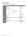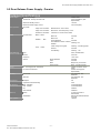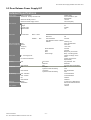
1
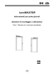
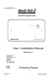
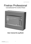
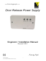
www.Protectingpeople.co.uk
Door Release Power Supply
Engineer / Installation Manual
Document: VI55.1
…Protecting People
Printed : 04/03/2004
Doc : Door Release Installation Instructions V55.1.doc
-1-
Door Release Power Supply Instillation Instructions VI55.1
Ventcroft Ltd
Door Release Power Supply Engineer / Installation Manual
First Printed: 10.12.03
Document :VI55.1
Revision: Rev 01
Last Revised : 22.12.03
Copyright © 2003 by Ventrcroft Ltd. All rights reserved. No part of this
manual may be reproduced or transmitted in any form or by any means,
electronic or mechanical, including photocopying, recording, or by any
information storage or retrieval system, without prior written permission
from the publisher.
Notice of Liability
Every effort has been made to ensure that this manual / instructions contains
accurate and current information. However, Ventcroft Ltd shall not be liable for
any loss or damage suffered by the readers as a result of information held
herein.
Trademarks.
Ventcroft and the Ventcroft logo / device are trademarks and Ventcroft Ltd
All other trademarks are acknowledged as trademarks of their respective
companies.
Printed: 04/03/2004
Doc : Door Release Installation Instructions V55.1.doc
–2–
Door Release Power Supply Instillation Instructions VI55.1
Engineer / Installation Manual
Table of Contents
1.0 Description........................................................................................................................................ 4
2.1 Features – Standard (VPS-24TRA300S) ......................................................................................... 4
2.2 Features – Premium – (VPS-24TRA300P)....................................................................................... 5
3.0 Kit Contents ...................................................................................................................................... 5
4.0 Technical Description ...................................................................................................................... 6
4.1 Terminal Descriptions - Door Release Power Supply (VPS-24TRA300S/P)......................................................................6
4.2 Jumper Settings .................................................................................................................................................................6
4.3 PSU Internal Safety Fuses.................................................................................................................................................7
4.3.1 F1 – 24V Supply – 500mA, Anti Surge / Timed. .............................................................................................................7
4.3.2 F2 – Mains Transformer Internal Fuse, 0.63A, 120 Deg (Non Replaceable). .................................................................7
4.3 Front Mounted LED Description.........................................................................................................................................8
4.3.1 LED Display Types Quick Look Up Guide. .....................................................................................................................8
4.3.2 Green LED – Power........................................................................................................................................................8
4.3.3 Amber LED – Fault .........................................................................................................................................................8
4.3.4 Red LED – Activation......................................................................................................................................................9
4.4 Front Mounted Key-Switch (Premium models only) ...........................................................................................................9
4.4.1 Latching facility .............................................................................................................................................................10
4.5 Internal Piezo Buzzer (Premium models only) .................................................................................................................10
5. Installation......................................................................................................................................... 11
5.1 General Installation Considerations. ................................................................................................................................11
5.3 Mounting and Fixing.........................................................................................................................................................12
5.3.1 PSU ..............................................................................................................................................................................12
5.4 Wiring and Termination....................................................................................................................................................12
5.4.1 Relay Contacts..............................................................................................................................................................12
5.4.2 Mains Terminal .............................................................................................................................................................13
5.4.3 Fire I/P ..........................................................................................................................................................................13
5.4.4 Manual Release ............................................................................................................................................................13
6.0 Commissioning............................................................................................................................... 14
6.1 Powering Up ....................................................................................................................................................................14
6.2 Testing .............................................................................................................................................................................14
7.0 Operation and Functionality.......................................................................................................... 14
7.1 Normal Quiescent. (ACTIVE)...........................................................................................................................................14
7.2 Release (RELEASE)........................................................................................................................................................14
7.2.1 Fire Input Release.........................................................................................................................................................14
7.2.2 Manual Release ............................................................................................................................................................15
7.2.3 Key-Switch Release (premium models only) ................................................................................................................15
7.3 Mute A Fault. ...................................................................................................................................................................15
8.0 Maintenance and Regular Testing ................................................................................................ 15
8.1 Regular System Testing...................................................................................................................................................15
9.0 Specifications ................................................................................................................................. 16
9.1 Door Release Power Supply - Standard ..........................................................................................................................16
9.2 Door Release Power Supply - Premier ............................................................................................................................17
9.3 Door Release Power Supply KIT .....................................................................................................................................18
Notes: .................................................................................................................................................... 19
Printed: 04/03/2004
Doc : Door Release Installation Instructions V55.1.doc
–3–
Door Release Power Supply Instillation Instructions VI55.1
1.0 Description
Ventcroft’s range of door retainer power supplies offers two models. The premium model is a feature
rich, simple to install and operate door retainer power supply with key-switch operation. The Standard
model offers fewer features but retains the simplicity of use and ease of instillation. The Fire trigger input
requires 16-30V @ only 0.5mA to release the doors. The Manual Trigger input requires any resistance of
less then 47KΩ to be applied across its contacts to release the doors, this makes it ideal for use with call
points and any other equipment with voltage free contacts. There is no need for any external fire panel
monitoring to be used as the PSU actively monitors the Fire trigger input to check if Fire Panel is still
present (selectable). The Power supply is controlled by a microprocessor which provides excellent
stability and allows the PSU to be used with a wide range of devices. The PSU also contains an external
watchdog, in the unlikely event of a microprocessor fault or failure the external watchdog will
automatically signal a fault and close all doors.
2.1 Features – Standard (VPS-24TRA300S)
•
Simple Instillation and Maintenance.
•
24V Output (unregulated).
•
Built in Heavy Duty Relay.
•
Capable of driving 10 x 24V 30mA Door Retainers, total of 300mA
•
Microprocessor Controlled.
•
Complete with Surface Mounting Double Gang Back box.
•
External Watchdog.
•
24V O/P Fuse Monitoring.
•
3 Front Mounted Status LED's (Power, Fault & Release).
•
Over-Load Protection.
•
Fault Enable/Disable Option.
•
System Integrity Fire Panel Monitoring.
•
Manual Release Terminal.
Printed: 04/03/2004
Doc : Door Release Installation Instructions V55.1.doc
–4–
Door Release Power Supply Instillation Instructions VI55.1
2.2 Features – Premium – (VPS-24TRA300P)
•
Simple Instillation, Maintenance and Fault Diagnosis.
•
24V Output (unregulated).
•
Built in Heavy Duty Relay.
•
Capable of driving 10 x 24V 30mA Door Retainers.
•
Microprocessor Controlled.
•
Complete with Surface Mounting Double Gang Back box.
•
External Watchdog
•
24V O/P Fuse Monitoring.
•
3 Front Mounted Status LED's (Power, Fault & Release).
•
Over-Load Protection.
•
Fault Enable/Disable Option.
•
System Integrity Fire Panel Monitoring.
•
Manual Release Terminal.
•
On Board Buzzer.
•
Class Change Enable/Disable Option.
•
Fault Mute Option.
•
Front Mounted - Release / Mute / Latch Key-switch.
3.0 Kit Contents
VDR-KIT, Door Retainer Kit Sold Complete With a mini Door Release Power Supply (VPS-24TRA300S) Standard Model, 24 Vdc un-regulated supply, built in heavy duty relay triggerable with three methods,
and three status LED’s and a Surface mount 24Vdc Door Retainer (VDR-S24) ; 24 Vdc +/- 15%, 30 mA,
0.6W, 83x83x46, 20daN Holding Force,0-40 Deg C,IP54
Contents 1 * Door Retainer Power Supply (VPS-24TRA300S)
1 * Surface Mount Door Retainer (VDR-S24)
1 * Deep Base Double Gang Surface Back Box.
1 * Engineer / Installation Manual
1 * User Manual
1 * Accessory Bag Containing: 2 * keys (Premium models only)
1 * Spare 500 mA Fuse
Printed: 04/03/2004
Doc : Door Release Installation Instructions V55.1.doc
–5–
Fig.1
Door Release Power Supply Instillation Instructions VI55.1
4.0 Technical Description
This section provides brief technical information about the functionality and setup of the Door
retainer power supply.
4.1 Terminal Descriptions - Door Release Power Supply (VPS-24TRA300S/P)
Mains
L
N
Relay
24V
OUT
Key
SW-SW
Manual
Fire I/P
Release
E
+
_
The Mains terminals are how the PSU receives its main power source. L terminal connects
to the Live mains wire, N connects to the Neutral mains wire and E is used to connect to
the mains earth wire. It is good practise to fit a Non switched fused spare, fitted with a 1A
fuses between the PSU and the mains supply. Any wiring or termination to mains supply
should be in accordance to IEE and, or regulations and carried out by a trained and
qualified electrician.
The Fire I/P Terminals are used to connect the PSU to the fire panel. These Terminals
should be connected to a suitable O/P on the Fire Panel. When these terminals receive a
voltage between 16V and 32V the PSU will close all the doors that are connected to it.
●
The Manual Release Terminal can also be used to close the doors, This terminal is
constantly monitored, to activate the release a resistance of less than 47kΩ should be
applied across these terminals.
●
●
The Switch terminals are used to connect the front mounted Key Switch (where available)
and should not used to connect to any other device.
+
_
These Terminals Provide the 24V Unregulated Output. 300mA MAX
●
This Connection is Common.
C
NC This Connection is Normally Closed.
NO This Connection is Normally Open.
4.2 Jumper Settings
Standard Models are fitted with the Fault Enable Pins only.
Premium Models are fitted with two sets of selection pins these are:Selection
Class Change
On
Off
Class Change Enabled - 16 second delay
Class Change Disabled - No delay
Fault
On
Off
Fault Monitoring Enabled – Fire I/P
Fault Monitoring Disabled – Fire I/P
All Models have overload protection and 24V O/P fuse monitoring. The Fault Enable option is used to
select fault reporting for the FIRE I/P.
Printed: 04/03/2004
Doc : Door Release Installation Instructions V55.1.doc
–6–
Door Release Power Supply Instillation Instructions VI55.1
Fig.2
4.3 PSU Internal Safety Fuses
The PSU has 2 internal safety fuses to protect the sensitive electronics from external current overloads
and short circuits, the internal transformer fuse is to conform to regulation and limit any risk of fire.
4.3.1 F1 – 24V Supply – 500mA, Anti Surge / Timed.
The 24V Supply Fuse protects the PSU circuitry, and any other device that are connected to it.
4.3.2 F2 – Mains Transformer Internal Fuse, 0.63A, 120 Deg (Non
Replaceable).
The Mains Transformer Internal Fuse protects the PSU from overheating. The chance of this fuse
blowing or breaking is very rare and highly unlikely and is circuit protection is mandatory and is nonreplaceable.
Printed: 04/03/2004
Doc : Door Release Installation Instructions V55.1.doc
–7–
Door Release Power Supply Instillation Instructions VI55.1
4.3 Front Mounted LED Description
The PSU has 3 front mounted status LED’s to
provide user feed back. The LED’s enable
engineer and user to distinguish and recognise
all status conditions of the PSU and system. A
Green LED shows the state of the power
supply, a Red LED displays the status of
activations and an Amber LED shows any Fault
conditions. The LED’s can operate in a number
of ways to show the PSU’s status. The LED’s
can be constantly illuminated and they can also
flash in a number of ways.
Fig.3
4.3.1 LED Display Types Quick Look Up Guide.
LED Description
Display
Constantly Illuminated
Flashing Once Per Seconds on and Off. (1Hz)
Slow Blink Once Every 5 Seconds (0.2 Hz)
Increasing Flash, the Flash rate increases with time. (0.5Hz to 3Hz)
Not Illuminated Off.
4.3.2 Green LED – Power
The Green provides feedback of the state of the Mains power supply.
Not illuminated
Constantly
illuminated.
Flashing once per
second.
1Hz
No Power Present to the device
Power Supply ok
Power Supply overload. Too much current being drawn from
the device
4.3.3 Amber LED – Fault
The Amber Fault Led is indicates faults present on the system.
Action
Not illuminated
Constantly
illuminated.
Flashing once
per second.
1Hz
Description
No Fault
General Fault
Fuse Blown or missing – 24V Supply not available
Printed: 04/03/2004
Doc : Door Release Installation Instructions V55.1.doc
–8–
Door Release Power Supply Instillation Instructions VI55.1
4.3.4 Red LED – Activation
The red activation LED provides the user with information about the type of activation.
Action
Description
Not illuminated
No Activation
Flashing 1 Hz,
Once per
second
Manual Release Latched or
Power Supply overload. Too much current being drawn
from the device (all LED’s Flashing)
Increasing Flash
Class Change in progress – 16 Second Delay
Constantly
Illuminated
Doors Being Released
4.4 Front Mounted Key-Switch (Premium models only)
The front mounted Key-Switch can be used for a variety of tasks. These Include:State
Action
Quiescent
Activate system and release doors
Fault
Mute
Class Change
Override Class change and release doors.
Latching
The Key-switch can be turned twice to enable the latch facility.
See below.
Activate system and release doors
To Release the doors at any time insert the key and turn clockwise to the release / mute position, all
LED’s will illuminate and the buzzer (Premium models only) will sound for approx 2 seconds and the
door(s) will be released. Turn the key back to its ACTIVE position. The door retainers are now active, if
the doors are opened they will be held open. If you require the doors to be latched closed (remain closed
indefinitely) see 4.4.1 Latching facility section below. Alternately the key can be turned to the release
position and left in this position. This however is not recommended as the keys can be removed by
unauthorised persons.
Mute
To mute a fault condition simply insert the key and turn the key clockwise to the release / mute position,
the fault will still be displayed but will only generate a small beep every 10 seconds.
Class change
When class change is enabled the doors will not close immediately in the event of the sounders being
activated, during this time the PSU will be pulsing the RED (release) LED and sounding the buzzer
(Premium models only), this will happen for approx 15 seconds before the doors are closed, during this
time the key can be turned to the release / mute position and override the class change and release the
doors immediately.
Printed: 04/03/2004
Doc : Door Release Installation Instructions V55.1.doc
–9–
Door Release Power Supply Instillation Instructions VI55.1
4.4.1 Latching facility
The PSU has the ability to latch the doors closed.
This means that the doors can remain closed
indefinitely. This is done by turning the key from
its active position to the release position, then
back to its active position then to the release
position and back to its active position. Simplified
– turning the key twice. The key can now be
removed and the doors will remain closed. To
cancel this feature simply insert the key and turn
to release and back to active again.
Fig.4
4.5 Internal Piezo Buzzer (Premium models only)
The Internal Piezo buzzer provides audible feed back to the users and engineers, and enhance the front
mounted LED’s.
Action
Description
PSU in quiescent
No Sound
Fault
Constant Tone
Class Change
Short Pulse Tone, speed increasing with time
Muted
Short Beep Every 15 Seconds.
Activation
Constant Tone
Printed: 04/03/2004
Doc : Door Release Installation Instructions V55.1.doc
– 10 –
Door Release Power Supply Instillation Instructions VI55.1
5. Installation
This section will cover the Considerations, Planning, installation and testing process, from mounting,
wiring to testing of the PSU.
5.1 General Installation Considerations.
When planning a Door Release Power Supply, the positioning of all components should be given careful
consideration before mounting, for accessibly of the user, accessibility for cabling and the type of surface
to be mounted too.
Fused Spare
Fire Panel
Door Release
Power Supply
Door Retainers
Fig.5
For wiring purposes as can be seen in fig.5 the PSU is wired between the Fire Panel and Door
Retainers. Each Door Release Power Supply can power a maximum of 300mA approx 10 standard 24V
Door Retainers. When mounting the PSU it should be ensured that there is sufficient space for cabling
and the fused spare. The fused spare can be mounted in a separate location.
The PSU can supply a maximum of 300mA, on average each door retainer will provide a load of
between 20mA and 30mA dependant on its type. If too many devices are connected to the PSU (i.e. the
current exceeds 300mA), a fault will be displayed. This fault will be displayed as all LED’s flashing and
buzzer beeping (Premium models only). During this time the power to the devices will be removed. After
15seconds the power will be re-applied briefly if there are still too many devices attached then the
system will remove power and wait another 15 seconds, this will continue until the current is reduced to
300mA or less.
Printed: 04/03/2004
Doc : Door Release Installation Instructions V55.1.doc
– 11 –
Door Release Power Supply Instillation Instructions VI55.1
5.3 Mounting and Fixing.
This section deals with the detail of mounting and connection the PSU.
5.3.1 PSU
(Double patress)
Preferred Mounting
Points
Preferred Mounting
Points
Fig.6
The PSU has been designed to fit a double patress and can be fitted flush or surface mount.
The PSU is supplied complete with a double patress.
5.4 Wiring and Termination.
This sections deals with the wiring and connection of the PSU to the mains supply and other external
devices.
5.4.1 Relay Contacts
Before making any connections to the PSU make sure that it is isolated from the mains supply.
Connect the chain of door release power supplies to the relay contacts. The preferred method is shown
below.
Door
Retainer (+)
C
NC
RELAY
NO
Door
Retainer (-)
+
-
Fig.7
24V OUT
Door Retainers are chained together, positive to positive and negative to negative. Up to 10 x 30mA door
retainers can be chained together using this PSU.
Printed: 04/03/2004
Doc : Door Release Installation Instructions V55.1.doc
– 12 –
Door Release Power Supply Instillation Instructions VI55.1
5.4.2 Mains Terminal
Connect the mains supply wires, observe the correct polarity. Live (Red) to “L”, Neutral (Black) to “N”
and Earth to “E”. Note before making any connections ensure the mains supply is off/ / isolated.
5.4.3 Fire I/P
Connect the fire panel to the PSU. There are several methods of connecting the fire panel t the PSU,
they are listed below.
Connecting the PSU to the sounder O/P.
The Sounder O/P of the Fire panel is connected to the Fire I/P of the PSU. Simply connect the Positive
Terminal of the sounder O/P to the Positive terminal of the Fire I/P and the negative terminal of the
sounder O/P to the negative terminal of the Fire I/P. Note : the PSU’s fault monitoring on the FIRE I/P
Terminals may not be supported by all makes of fire panel, this feature can be disabled by moving the
FAULT selection header to the OFF position.
Connecting the PSU to the Fire O/P
The Fire O/P of the Fire panel is connected to the Fire I/P of the PSU. Simply connect the Positive
Terminal of the Fire O/P to the Positive terminal of the Fire I/P and the negative terminal of the Fire O/P
to the negative terminal of the Fire I/P. Note : the PSU’s fault monitoring may not be supported by all
makes of fire panel, this feature can be disabled by moving the FAULT selection header to the OFF
position.
Connecting the PSU to a relay.
The Fire I/P is connected to a switched relay contact. The relay should be capable of switching 24V DC
to the Fire I/P terminals.
5.4.4 Manual Release
The manual release terminals can be connected to almost any voltage free contacts such as call points
or relays. The Manual release should be connected as shown below.
Manual
Release
Manual
Release
Fig.8
Resistance
≤ 47KΩ
Printed: 04/03/2004
Doc : Door Release Installation Instructions V55.1.doc
– 13 –
Door Release Power Supply Instillation Instructions VI55.1
6.0 Commissioning
This section sets out to ensure that the Door Release PSU has been completely tested and the User is
comfortable with is operation.
6.1 Powering Up
Once the system is fully installed, the door retainers wired correctly and the front cover fitted the mains
supply can now be applied to the PSU.
The Front Mounted LED’s will now flash in sequence RED, YELLOW then GREEN, the buzzer should
sound with each LED (Premium models only). Once all the LED’s have been illuminated the RED and
YELLOW LED’s should go off, leaving only the GREEN Power LED. The PSU is now in its quiescent
mode and is awaiting a trigger signal on one of its inputs.
6.2 Testing
The Entire Door Retainer System should now be thoroughly tested.
Each Trigger input should be activated in turn and all doors connected to the PSU should close.
7.0 Operation and Functionality
This section sets out to detail the operation and functionality of the Door Release PSU and how to
“Activate” and “Reset” the System.
7.1 Normal Quiescent. (ACTIVE)
Normal Quiescent mode is when the PSU is in standby and waiting to receive a valid trigger from the fire
panel or any of its other terminals (if connected).
In “Normal Quiescent Mode” the PSU has mains power supplied and only the Green power LED is
illuminated.
7.2 Release (RELEASE)
“Release” occurs when a valid signal has been received from one or more of the PSU’s input terminals
i.e. Fire Panel, Call Point, key-switch, or any other appropriate devices connected.
7.2.1 Fire Input Release
A fire input release occurs when the PSU receives a valid signal from the Fire panel at the FIRE INPUT
terminals. The microprocessor will take several samples of the data before deciding if it is valid, once the
decision is made to release the doors the microprocessor will switch over the relay contact, illuminate the
RED (RELEASE) LED and sound the buzzer (Premium models only). This will continue as long as there
continues to be a valid signal from the fire panel, once this signal stops the relay is switched back to its
original position and the doors can now be held open. If class change is enabled then there will be a
delay from the start of the signal from the fire panel to the doors being closed (approx 15sec). If the
signal is removed before the delay ends then the doors will not close. E.g. if the bells are sounded for 5
seconds for class change then the doors will not close.
Printed: 04/03/2004
Doc : Door Release Installation Instructions V55.1.doc
– 14 –
Door Release Power Supply Instillation Instructions VI55.1
7.2.2 Manual Release
A manual release occurs when the PSU receives a valid signal from the MANUAL RELEASE terminals,
the microprocessor constantly monitors these terminals for a resistance of less than 47kΩ if a resistance
of less than 47kΩ is measured then the microprocessor will switch over the relay contact, illuminate the
RED (RELEASE) LED and sound the buzzer (Premium models only). If the signal form the MANUAL
RELEASE contact remains after the doors have been release the RED (RELEASE) LED will continue to
flash and the buzzer (Premium models only) sound in sympathy will the LED until the signal is removed.
Once the signal is removed the relay is switched back to its original position and the doors can now be
held open.
7.2.3 Key-Switch Release (premium models only)
A key-switch release occurs when the PSU receives a valid signal from the KEY-SW terminals, the
microprocessor constantly monitors these terminals for the actuation of the key-switch. Once an
activation has occurred then the microprocessor will switch over the relay contact, illuminate the RED
(RELEASE) LED and sound the buzzer (Premium models only). The microprocessor will also be
monitoring the KEY-SW terminal for the latched state. See 4.4.1 Latching facility. Once the signal is
removed the relay is switched back to its original position and the doors can now be held open
7.3 Mute A Fault.
During a fault condition the buzzer(Premium models only) will be sounding continuously, to mute the
buzzer simply turn the key-switch clockwise to the RELEASE / MUTE position and back anticlockwise to
the ACTIVE position, the buzzer will now be silent and will only produce a small beep every 10 seconds.
8.0 Maintenance and Regular Testing
This section details the regular and necessary testing and inspection of the Door Retainer Power Supply.
Its is just as important to provide regular testing and maintenance of the system as it is to install the
system correctly.
8.1 Regular System Testing.
The entire system to be tested regularly to ensure the system is always ready for use.
The testing is simple simply activate each input in turn and check that all doors connected to the PSU
close. E.g. Turn the key-switch clockwise to the RELEASE position and make sure all doors have
closed, turn the key-switch back to the ACTIVE position and open all doors. Trigger the MANUAL
RELEASE Terminals (if fitted) and make sure all doors have closed, reset the trigger on the MANUAL
RELEASE and open all the doors. Trigger the Fire Panel alarms check that all the doors connected to
the PSU have closed, silence/reset the Fire Panel alarms and open all the doors.
It is recommended that the whole system be tested a minimum of at least once per month, but it is
desirable to fully test or part the system on a weekly basis.
Printed: 04/03/2004
Doc : Door Release Installation Instructions V55.1.doc
– 15 –
Door Release Power Supply Instillation Instructions VI55.1
9.0 Specifications
9.1 Door Release Power Supply - Standard
Detailed Specifications
Power Supply
LED's
Mains Input Voltage
230Vac 50Hz
Transformer Primary Thermal Fuse
Quiescent Standby Current
0.63A 102 DEG C. (Non
Replaceable)
15mA dc
Maximum Overall Supply Current
300 mA dc (Max.)
Front
Mains - Green
Mounted
Release - Red
Fault - Yellow
Fuses
Mains On
Constant
Total Power Failure
Off
Doors Released
Constant
Doors Latched – Manual Release
Flashing 1 Hz
General Fault
Constant
Fuse Blown/Missing
Flashing 1 Hz
F1: 24V Supply Fuse - Monitored
500mA Anti Surge 20mm
Glass
630mA 120 Deg (NonReplaceable).
F2: Internal Transformer
Housing
Front Cover
European
Polycarbonate - Fire
Retardant.
Polycarbonate - Fire
Retardant.
CE
Ingression Protection Rating.
IP20
PSU - Standard
VPS-24TRA300S
PSU - Premier
VPS-24TRA300P
KIT
VDR-KIT
Door Retainer
VDR-S24
Period
2 Years from Date of
Manufacture
Date of Manufacture Marked
On PCB
18/12/03
Back Box
Compliance
Re-Ordering
Warranty
Identification
Last Updated
Printed: 04/03/2004
Doc : Door Release Installation Instructions V55.1.doc
– 16 –
Door Release Power Supply Instillation Instructions VI55.1
9.2 Door Release Power Supply - Premier
Detailed Specifications
Power Supply
User Operation
LED's
Quiescent Standby Current
230Vac 50Hz
0.63A 102 DEG C. (Non
Replaceable)
15mA dc
Maximum Overall Supply Current
300 mA dc (Max.)
Mains Input Voltage
Transformer Primary Thermal Fuse
Key-switch
Front Mounted
Single Turn Clockwise
Release Doors – Doors close
Single Turn Clockwise
Mute Fault – short beep every 15 sec.
Double turn Clockwise
Latch Doors – Doors remain closed
Mains - Green
Mains On
Constant
Mains Fail
Off
Doors Released
Constant
Release
- Red
Door Release Latched – Manual
Flashing 1 Hz
Release
Fault - Yellow
Class Change In Progress
Flashing – Increasing speed
General
Constant
Fuse Missing
Flashing - 1 Hz
P
Internal Buzzer
Type
Premium models only
Current
Peizo, PCB Mounted
5mA max.
Frequency
Sounds
Fuses
1 Khz Tone
Doors Released
Fault
Mute
Class Change
F1: 24V Supply Fuse - Monitored
500mA Anti Surge 20mm
Glass
630mA 120 Deg (NonReplaceable).
F2: Internal Transformer
Housing
Front Cover
European
Polycarbonate - Fire
Retardant.
Polycarbonate - Fire
Retardant.
CE
Ingression Protection Rating.
IP20
PSU - Standard
VPS-24TRA300S
PSU - Premier
KIT
VPS-24TRA300P
VDR-KIT
Door Retainer
VDR-S24
Period
2 Years from Date of
Manufacture
Date of Manufacture Marked
On PCB
18/12/03
Back Box
Compliance
Re-Ordering
Warranty
Constant
Constant
Beep Every 10 Seconds
Beep - Increasing speed
Identification
Last Updated
Printed: 04/03/2004
Doc : Door Release Installation Instructions V55.1.doc
– 17 –
Door Release Power Supply Instillation Instructions VI55.1
9.3 Door Release Power Supply KIT
Detailed Specifications
Power Supply
Door Retainer
PSU LED's
Quiescent Standby Current
230Vac 50Hz
0.63A 102 DEG C. (Non
Replaceable)
15mA dc
Maximum Overall Supply Current
300 mA dc (Max.)
Holding Force
20daN
Voltage
24
Nominal Power
0.6Watt
Release Button
Yes
Mains Input Voltage
Transformer Primary Thermal Fuse
Front Mounted
Mains - Green
Release
PSU Internal Buzzer Type
Premium models only Current
Frequency
Sounds
PSU Fuses
- Red
Mains On
Constant
Mains Fail
Off
Doors Released
Constant
Door Release Latched – Manual
Flashing 1 Hz
Release
Peizo, PCB Mounted
5mA max.
1 Khz Tone
Doors Released
Fault
Mute
Class Change
F1: 24V Supply Fuse
500mA Anti Surge 20mm
Glass
630mA 120 Deg (NonReplaceable).
F2: Internal Transformer
Housing
PSU
Compliance
Re-Ordering
Warranty
Constant
Constant
Beep Every 10 Seconds
Beep - Increasing speed
Polycarbonate - Fire
Retardant.
Door Retainer
PSU
Front Cover
Back Box
Box
European
Door Retainer
Ingression Protection Rating.
Conformity
IP20
EN1155, BS5839
Ingression Protection Rating
IP52
Grey Ral 9002 Painted Steel
CE
PSU - Standard
VPS-24TRA300S
PSU - Premier
VPS-24TRA300P
KIT
Door Retainer
VDR-KIT
VDR-S24
Period
2 Years from of Manufacture
Identification
Date of Manufacture Marked
On PCB
18/12/03
Last Updated
Printed: 04/03/2004
Doc : Door Release Installation Instructions V55.1.doc
– 18 –
Door Release Power Supply Instillation Instructions VI55.1
Notes:
Printed: 04/03/2004
Doc : Door Release Installation Instructions V55.1.doc
– 19 –
Door Release Power Supply Instillation Instructions VI55.1
Technical Help
If you have any difficulties with this product please call our technical help line.
Tel. 01928581098
Fax. 01928581099
ALL INFORMATION IS GIVEN IN GOOD FAITH BUT WITHOUT WARRANTY.
IN THE INTEREST OF CONTINUAL PRODUCT DEVELOPMENT VENTCROFT LTD, RESERVE THE RIGHT TO MODIFY PRODUCTS WITH OUT PRIOR NOTICE.
VENTCROFT AND THE VENTCROFT DEVICE ARE ALL TRADEMARKS OF VENTCROFT LTD
VENTCROFT 2002 ©
Printed: 04/03/2004
Doc : Door Release Installation Instructions V55.1.doc
– 20 –
E&OE