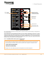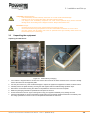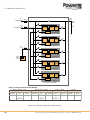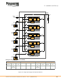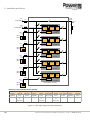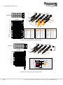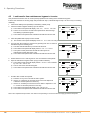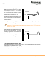
1
PowerWAVE 9500DPA
500 kW Modular UPS
User Manual
Document Control
ISSUE
DATE
Issue 1.0
01-05-14
REVISION SUMMARY
Initial issue.
UPS740-01-00 PowerWave PW9500DPA User Manual - Issue 1.0 (Dated 01-05-14)
Uninterruptible Power Supplies Ltd has taken every precaution to
produce an accurate, complete and easy to understand manual and
will therefore assume no responsibility nor liability for direct,
indirect or accidental personal or material damage due to any
misinterpretation of or accidental mistakes in this manual.
© 2014 Uninterruptible Power Supplies Ltd
This manual may not be copied nor reproduced without written
permission of Uninterruptible Power Supplies Ltd.
UPS740-01-00 PowerWave PW9500DPA User Manual - Issue 1.0 (Dated 01-05-14)
Table of Contents
Safety
1
1.1 Description of the safety symbols used in this manual
1
1.2 User precautions
1
1.3 Important safety notes
2
1.4 Storage instructions
2
1.5 Terminology
3
General Description
4
2.1 Introduction
4
2.2 Model range
5
2.3 Functional description of operation
2.3.1 UPS Module internal operation
2.3.2 UPS Module operational states
2.3.3 UPS system operation
2.3.4 Parallel system operation
6
6
7
8
9
2.4 PowerWave 9500 User controls
10
2.5 Power isolators
2.5.1 PowerWave 9500 cabinet power configurations
10
11
2.6 Customer interface board
13
2.7 UPS Module control panel
2.7.1 Operator keys
2.7.2 Module mimic leds
2.7.3 Power Management display
14
14
14
16
2.8 System control panel
2.8.1 Display header bar
2.8.2 Mimic Diagram – system level
2.8.3 Module selection screen
2.8.4 Home screen
19
20
21
22
24
2.9 Warranty
2.9.1 Extended warranty
2.9.2 Additional service/maintenance support
26
26
26
2.10 Extended Service enquiry form
27
Installation and Set-up
28
3.1 Introduction
28
3.2 Taking receipt of the UPS
3.2.1 Site transportation
28
28
3.3 Unpacking the equipment
29
3.4 Storage
30
3.5 Planning the installation (site and environmental considerations)
30
UPS740-01-00 PowerWave PW9500DPA User Manual - Issue 1.0 (Dated 01-05-14)
I
3.6 Planning the installation (cabling considerations)
3.6.1 General requirements
3.6.2 Cable and fuse sizing
3.6.3 Power cable terminations
3.6.4 Parallel cabinet cabling recommendations
31
31
32
37
39
3.7 UPS Cabling procedure
3.7.1 Connecting the UPS input cables
3.7.2 Connecting the UPS output cables
3.7.3 Connecting the battery cables
40
40
41
41
3.8 Multi-cabinet parallel control cabling and configuration
3.8.1 Connecting the parallel communication bus cables
3.8.2 Connecting the multidrop cables
3.8.3 Module customer interface facilities
42
43
44
45
Operating Procedures
46
4.1 Introduction
4.1.1 Operating procedure summary
4.1.2 This chapter contains the following operating procedures:
46
46
46
4.2 Initial system power-up and functional testing
47
4.3 Total system shutdown
50
4.4 Load transfer from inverter to maintenance bypass
51
4.5 Load transfer from maintenance bypass to inverter
52
4.6 UPS module replacement
4.6.1 General information
4.6.2 Replacing a module in a single module UPS system
4.6.3 Replacing a module in a redundant parallel module system
4.6.4 Replacing a module in a capacity parallel module system
53
53
53
55
57
Maintenance
61
5.1 Introduction
61
5.2 User responsibilities
61
5.3 Routine maintenance
61
5.4 Battery maintenance
62
5.5 Battery testing
5.5.1 Battery test procedure
62
62
Troubleshooting
63
6.1 Fault and alarm indications
63
6.2 Fault identification and rectification
64
6.3 Contacting service
64
Options
65
7.1 Customer interface options
7.1.1 Introduction
7.1.2 Serial RS-232/ USB Computer interface – JD1 & USB (Smart Port)
7.1.3 Dry ports customer interface (X2, X3)
7.1.4 RS485 Interface for multidrop – JR2
7.1.5 RS485 Interface for remote panel – JR3
7.1.6 SNMP Card slots
II
65
66
66
66
68
68
69
UPS740-01-00 PowerWave PW9500DPA User Manual - Issue 1.0 (Dated 01-05-14)
7.2 UPS Monitoring and automated control software
7.2.1 The importance of UPS management
7.2.2 WAVEMON Shutdown and Management Software
7.2.3 Functional description
7.2.4 Licensing
7.2.5 RCCMD Server shutdown
Specification
69
69
70
71
71
71
72
8.1 Introduction
72
8.2 Mechanical data
8.2.1 UPS Cabinet
8.2.2 100 kVA UPS Power module
72
72
73
8.3 100 kVA UPS Module data
8.3.1 General Data
8.3.2 Rectifier data
8.3.3 Battery data
8.3.4 Inverter data
8.3.5 Static bypass data
8.3.6 Environmental data
73
73
74
74
75
75
76
8.4 Standards
76
UPS740-01-00 PowerWave PW9500DPA User Manual - Issue 1.0 (Dated 01-05-14)
III
:
IV
UPS740-01-00 PowerWave PW9500DPA User Manual - Issue 1.0 (Dated 01-05-14)
1: Safety
1
1.1
Safety
Description of the safety symbols used in this manual
WARNING: The warning symbol is used where there is danger of an electrical shock, equipment damage or
personal-injury.
CAUTION: The caution symbol is used to highlight important information to avoid possible equipment
malfunction or damage.
1.2
User precautions
WARNING: Ensure you read and understand all the safety and hazard warnings contained in this manual
before you begin to install this equipment.
WARNING: Keep this manual with the UPS for future reference.
WARNING: The UPS and peripheral equipment must be installed by a suitably qualified engineer who is aware
of the potential shock hazards.
WARNING: Before it is put into service, this UPS must be set-up and commissioned by a suitably qualified
engineer in accordance with the procedures contained in Chapter 3.
WARNING: This UPS does not contain any user-serviceable parts. If the UPS develops a fault it must be
repaired by a trained engineer.
You run risk of exposure to dangerous voltages if you open UPS-covers!
Uninterruptible Power Supplies Ltd will assume no responsibility or liability for accidents or injuries due to
incorrect operation or manipulation of the UPS or peripheral equipment.
CAUTION: The PowerWave 9500 is a Class A UPS product (according to EN 62040-3).
In a domestic environment the UPS may cause radio interference and the user may be required to undertake
additional measures.
UPS740-01-00 PowerWave PW9500DPA User Manual - Issue 1.0 (Dated 01-05-14)
1
1: Safety
1.3
Important safety notes
CAUTION: Please read the following notes carefully prior to installation.
The PowerWave 9500 UPS contains components that carry high current and voltages and must be installed by a suitably
qualified service specialist. The UPS does not contain any user-serviceable parts, so if it malfunctions it must be serviced
or repaired by a trained engineer.
To prevent the UPS from overheating, the UPS ventilation grills must be kept free of obstructions at all times. A space of
at least 200 mm (8 in) should be provided at the back of the UPS and 100 mm (4 in) at each side of the UPS to allow
adequate airflow from the ventilation fans.
The UPS is must be installed in a sheltered and controlled environment away from direct sunlight. The operating
temperature should be between 0°C and +40°C (ideally in the range +20°C to +25°C) with a maximum relative humidity of
95%, non-condensing.
Before installing the equipment you must check to ensure that the UPS input voltage stated on the UPS data-plate on the
back of the unit matches your local utility supply voltage.
The UPS warranty will be rendered void, and the manufacturer reserves the right to refuse replacement or compensation
in the following events:
• Accidental damage to the UPS.
• Ingress of liquids or foreign bodies.
• Damage or malfunction due to installing the UPS in an environment that fail to meet the conditions specified in this
manual.
• Damage or malfunction due to improper installation, configuration or maintenance carried out by an unauthorised
person.
1.4
Storage instructions
If you intend to store the UPS for an extended period, in a moderate climate, the batteries should be charged for 12 hours
every 6 months by connecting the UPS to the utility supply. If the ambient temperature at the storage location is above
30°C, this should be carried out every 2 months
2
UPS740-01-00 PowerWave PW9500DPA User Manual - Issue 1.0 (Dated 01-05-14)
1: Safety
1.5
Terminology
The following terms are used in this manual to described various UPS system configurations.
Active sub-module
}
ON /OFF
E NTE R
R ESE T
ON /OFF
Passive sub-module
UPS Module
or
Single Module System
ON/ OF F
ENT E R
RES E T
ENT E R
RES E T
ENT E R
RES E T
ON/ OF F
UPS Module 05
dd.mm.yy hh:mm:ss
Loadprotected
P:01
load
r ectifier
inver ter
ON/ OF F
ON/ OF F
UPS Module 04
}
ON/ OF F
ON/ OF F
UPS Module 03
ON/ OF F
ENT E R
RES E T
ENT E R
RES E T
Parallel UPS System
or
Multi-module System
ON/ OF F
UPS Module 02
Fully populated PW9500 cabinet containing
5 x UPS Modules operating in parallel.
ON/ OF F
ON/ OF F
UPS Module 01
ON/OFF
ON O
/ F F
EN TER
RE SET
ON O
/ F F
ENTER
RESET
ON/OFF
ENTER
RESET
ON/OFF
ENTER
RESET
ON/OFF
ENTER
RESET
ENTER
RESET
ON/OFF
ENTER
RESET
ON/OFF
ENTER
RESET
ON/OFF
ENTER
RESET
ON/OFF
ENTER
RESET
ENTER
RESET
dd.m m.yy hh:mm:ss
Load protec te d
P:01
loa d
re ctifier
in ve rte r
ON/OFF
ON O
/ F F
EN TER
RE SET
EN TER
RE SET
EN TER
RE SET
EN TER
RE SET
ON O
/ F F
ON/OFF
ON/OFF
ON O
/ F F
ON O
/ F F
ON/OFF
ON/OFF
ON O
/ F F
ON O
/ F F
ON/OFF
ON/OFF
ON/OFF
ON O
/ F F
ON O
/ F F
Cabinet 1
ON/OFF
ON/OFF
Cabinet 2
Multi-cabinet System
or
Parallel Cabinet System
ON/OFF
Cabinet 3 -4 -5
ON/OFF
Cabinet 6
Up to six PW9500 cabinets can be connected in
parallel to effectively offer a multi-module system
containing up to 30 (6x5) parallel UPS Modules.
UPS740-01-00 PowerWave PW9500DPA User Manual - Issue 1.0 (Dated 01-05-14)
3
2: General Description
2
2.1
General Description
Introduction
Congratulations on your purchase of the PowerWave 9500 UPS.
Continuous power availability is essential in today’s dynamic IT and process-related work environments. It is equally
important that any installed power protection system is sufficiently resilient and adaptable to handle inevitable changes
brought about by the introduction of new server technologies, migration and centralization.
Such demands are well met by the PowerWave 9500 UPS system, which provides the foundation for continuous power
availability of network-critical infrastructures both in enterprise data centres, where business continuity has paramount
importance, and in process control environments where manufacturing continuity is essential.
Reliability and quality standards
The PowerWave 9500 UPS incorporates the latest technological developments in power engineering. Representing a
completely new generation of high power three phase UPS systems, its advanced double conversion VFI (Voltage and
Frequency Independent) topology responds fully to both the highest availability and environmentally friendly requirements
compliant with IEC 62040-3 (VFI-SS-111) standards.
Uninterruptible Power Supplies Ltd specialises in the installation and maintenance of Uninterruptible Power Systems; and
this powerful UPS is just one example of our wide range of state-of-the-art power protection devices that will provide your
critical equipment with a steady and reliable power supply for many years.
Key features
High reliability, upgrade ability, low operating costs and excellent electrical performance are just some of the highlights of
this advanced UPS system. Other key features include :
• Decentralised Parallel Architecture (DPA) – Each UPS module contains its own bypass circuit, which greatly
improves the overall system reliability by removing a common point of failure that is often present in more
traditional UPS systems.
• Truly modular design – The PowerWave 9500 is designed around 100 kW rated UPS modules.
• System expandability – Each PowerWave 9500 cabinet can contain up to five UPS modules (500 kW), and up to
six cabinets can be connected together to offer a parallel system capacity of 3.0 MW.
• Hot-swappable modules – Enables system expansion and module replacement to be carried out without disturbing
the connected load.
• Unity output power factor (kVA=kW) – Blade server friendly. No de-rating required with leading PF loads.
• Best in class AC-AC efficiency – up to 96% efficiency minimises operational costs (TCO).
• Low input power factor (0.99 @ 100% load) – Cost savings during installation and the entire life cycle (TCO).
• Ease of operation – A graphical display panel on the front of the UPS cabinet provides the operator with a single
point of ‘system level’ control, and also allows the operation of each individual module to be interrogated.
• Flexible battery management – Advanced management of battery charging and preventive failure diagnostics
avoids premature deterioration of battery life.
• Top or bottom cable entry – Allows flexible installation into existing plant infrastructure.
• Very low input current distortion – THDi = < 3.5% @ 100% load leads to savings in generator-set power and
installation costs.
4
UPS740-01-00 PowerWave PW9500DPA User Manual - Issue 1.0 (Dated 01-05-14)
2: General Description
2.2
Model range
As described above, the PowerWave 9500 UPS cabinet can house up to five 100 kW UPS modules, so each cabinet can
be rated up to 500 kW in 100 kW increments.
ON/ OF F
ENT E R
RES E T
ENT E R
RES E T
ENT E R
RES E T
ENT E R
RES E T
ENT E R
RES E T
ON/ OF F
UPS Module 05
dd.mm.yy hh:mm:ss
Loadprotected
P:01
load
r ectifier
inver ter
ON/ OF F
UPS Module
Active sub-module
ON/ OF F
UPS Module 04
UPS Cabinet
ON /OFF
E NTE R
R ESE T
ON /OFF
ON/ OF F
ON/ OF F
UPS Module 03
Passive sub-module
ON/ OF F
ON/ OF F
UPS Module 02
ON/ OF F
ON/ OF F
UPS Module 01
Figure 2.1 PowerWave 9500 System hardware
Each UPS module comprises two sub-modules, one is known as the ‘Active sub-module’ and the other as the ‘Passive
sub-module’. These are mounted in the UPS cabinet in pairs, with the Active sub-module located on top of the Passive
sub-module. The first module to be installed in the cabinet must be fitted to the bottom position with subsequent modules
fitted in the next lowest available space. Each module is assigned an ID number when it is installed in the cabinet, to allow
it to be identified by the system control logic for purposes such as monitoring and event logging etc. The modules fitted in
the first cabinet should be identified as illustrated in Figure 2.1. In a multi-cabinet installation, the modules in the second
cabinet are given an identity ‘06’ to ‘10’, those in the third cabinet are given ‘11’ to ‘15’, and so on.
The following table shows the static parameters for each configuration.
1 Module
2 Module
3 Module
4 Module
5 Module
System power rating (per cabinet) (kVA/kW)
100
200
300
400
500
Cabinet weight including modules (kg)
539
648
757
866
975
18000
22500
Cabinet weight without fitted modules (kg)
430
Cabinet dimensions (w x h x d) mm
1580 x 1975 x 940
Heat dissipation 100% linear load (W)
4500
9000
Heat dissipation 100% linear load (BTU)
15395
30717
46076
61434
76793
Heat dissipation 100% non-linear load (W)
5710
11420
17130
22840
28550
Heat dissipation 100% non-linear load (BTU)
19488
38976
58465
77953
97441
660
1320
1980
2640
3300
1200
2400
3600
4800
6000
Heat dissipation no load (W))
Acoustic noise (@ 1m)
Cooling airflow (25°C - 30°C) at full load (m³/s)
Installation clearances (mm)
UPS Module weight
UPS Module dimensions (w x h x d) mm
13500
TBA
Front 1500, Side 100, Rear 200, Top 400
Active sub-module = 55 kg, Passive sub-module = 54 kg
Active & Passive modules 710 x 178 x 750
UPS740-01-00 PowerWave PW9500DPA User Manual - Issue 1.0 (Dated 01-05-14)
5
2: General Description
2.3
Functional description of operation
This section describes:
•
•
•
•
A block-diagram level description of the individual UPS module internal operation (see paragraph 2.3.1).
The various UPS module operational states (see paragraph 2.3.2).
UPS system operation – ‘On-line’ versus ‘Off-line’ system operation (see paragraph 2.3.3).
Multi-module system operation and paralleling considerations (see paragraph 2.3.4).
2.3.1 UPS Module internal operation
Bypass Line
DC/AC
INVERTER
EMI
UPS
Mains
Input
DC BOOST
CONVERTER
EMI
AC/DC (PFC)
RECTIFIER
UPS AC
Output
STATIC
SWITCH
Automatic
Batt. Switch
BATT. CHARGER
BATTERY
Figure 2.2 UPS module functional block diagram
EMI Filters
The input and output EMI filters reduce the electromagnetic noise generated by the UPS – i.e. reduces radio interference.
Rectifier
The rectifier uses leading-edge switched-mode techniques which results in a UPS input power factor of almost unity over
its operating range (0.99 at full rated linear load). It converts the UPS AC mains input to an unregulated DC power source
that can satisfy the inverter DC power demands over an input voltage range of between 160V~288V. This wide input
voltage range means that the battery is not called upon even during substantial power dips (brown outs), which maximises
battery life and availability.
DC Boost converter
The DC boost converter converts the unregulated DC voltage connected to its input, from either the rectifier or battery, into
a regulated DC bus suitable for powering the inverter.
Battery charger
A multi-stage battery charger, powered from the DC boost converter output, charges the battery whenever the input
supply is available and the rectifier/DC boost converter is turned on. The charger uses an intelligent charging profile to
obtain the best battery charge/discharge performance in order to optimise the battery life.
Inverter
The inverter converts the regulated DC voltage produced by the DC boost converter into a sinusoidal AC output voltage
suitable for connecting to the load. In addition to providing output voltage regulation, the inverter control logic also
provides various levels of overload protection, frequency regulation and synchronisation, and output voltage error
detection.
Static switch
The static switch provides a means of connecting the UPS AC output terminals to either the inverter or the bypass line
(which is connected directly to the raw UPS mains input supply). The static switch control logic will automatically transfer
the load from the inverter to the bypass supply in the event of an overload or UPS (inverter) malfunction. A no-break
transfer will take place if the inverter frequency and the bypass supply frequency is synchronised.
6
UPS740-01-00 PowerWave PW9500DPA User Manual - Issue 1.0 (Dated 01-05-14)
2: General Description
Automatic battery switch
If UPS mains input supply fails, the battery is automatically connected to the input of the DC boost converter by means of
an electronically controlled switch. This enables the inverter to continue its normal operation and maintain the UPS output
load supply from battery power.
2.3.2 UPS Module operational states
UPS OFF
Figure 2.3 shows the internal operation of the UPS
module when the inverter is turned OFF from the
module control panel:
EMI
DC/AC
INVERTER
UPS AC
Output
EMI
UPS
Mains
Input
DC BOOST
CONVERTER
UPS AC
Output
EMI
AC/DC (PFC)
RECTIFIER
EMI
• If the mains input supply is still available, the
battery charger continues to charge the
battery, via the rectifier/DC boost converter.
• The static switch turns on its ‘bypass’ arm to
connect the UPS output to the module’s raw
mains bypass supply.
If the UPS module shuts down due to a fault, a
contactor connected immediately ahead of the UPS
output (not illustrated) will open to fully isolate the
UPS from the remainder of the UPS system.
Bypass Line
UPS AC
Output
STATIC
SWITCH
Automatic
Batt. Switch
BATT. CHARGER
BATTERY
Figure 2.3 UPS OFF
UPS ON-LINE Mode
Figure 2.4 illustrates the UPS ON-LINE mode, which
is considered the ‘normal’ mode of operation:
AC/DC (PFC)
RECTIFIER
UPS
Mains
Input
DC BOOST
CONVERTER
DC/AC
INVERTER
EMI
• The rectifier and DC boost converter are
turned on to supply controlled DC power to
the inverter input.
• The battery charger charges the battery.
• The inverter converts the DC supplied by the
rectifier back into AC suitable for connecting
to the load.
• The inverter arm of the static switch is turned
on to connect the inverter output to the UPS
output terminals to provide the load with
processed power.
Bypass Line
STATIC
SWITCH
Automatic
Batt. Switch
BATT. CHARGER
BATTERY
Figure 2.4 UPS ON-LINE
UPS ON-BATTERY Mode
The UPS automatically changes to the ON-BATTERY
mode if the mains input supply fails during normal
(ON-LINE) operation:
AC/DC (PFC)
RECTIFIER
UPS
Mains
Input
DC BOOST
CONVERTER
DC/AC
INVERTER
EMI
• The battery discharges through the DC boost
converter which regulates the battery voltage
at the level required by the inverter.
• The inverter converts the DC supplied by the
boost converter back into AC suitable for
connecting to the load.
• The inverter arm of the static switch remains
closed to maintain the connection from the
inverter to the UPS output (load) terminals.
Bypass Line
STATIC
SWITCH
Automatic
Batt. Switch
BATT. CHARGER
BATTERY
Figure 2.5 UPS ON-BATTERY
UPS740-01-00 PowerWave PW9500DPA User Manual - Issue 1.0 (Dated 01-05-14)
7
2: General Description
UPS ON-BYPASS Mode
AC/DC (PFC)
RECTIFIER
UPS
Mains
Input
DC BOOST
CONVERTER
DC/AC
INVERTER
EMI
• The load is connected to the raw mains input
supply through the bypass arm of the static
switch.
• The rectifier and inverter remain powered up
and operational in readiness to be brought
into use.
• When operating in this mode the load is not
protected against any mains input supply
disturbances or loss.
Bypass Line
EMI
This mode can be selected by the operator as part of
the system operating procedure. It is also entered
following certain fault occurrences such as a UPS
output overload:
UPS AC
Output
STATIC
SWITCH
Automatic
Batt. Switch
BATT. CHARGER
BATTERY
Figure 2.6 UPS ON-BYPASS
2.3.3 UPS system operation
Summary of UPS module operating modes
UPS installations are generally categorised as being either ‘On-line’ or ‘Off-line/On stand-by’ systems, and you can
configure the PowerWave 9500 to operate as either type. The two systems are described below.
On-line UPS system
An ‘on-line’ system provides the highest degree of load protection, especially in the event of a mains supply disturbance or
complete failure, and we always recommended its use if the critical load (e.g. computer system) will not tolerate even a
very brief supply interruption.
When the PowerWave 9500 is used as an ‘on-line’ UPS it is configured to normally operate in the ON-LINE mode, as
shown in Figure 2.4. In the event of a mains supply failure, the UPS changes to its ON-BATTERY mode (Figure 2.3)
without affecting its output supply – i.e the changeover to battery operation is totally transparent at the UPS output. The
UPS then continues to provide its rated output until the battery discharges to a low cut-off point, at which time the UPS will
try to switch to bypass and then shut down in a controlled manner. An alarm will warn that the battery is discharging to
enable the operator to take any necessary intervention to protect the load integrity.
It is usual, especially in larger installations, to provide the UPS with an alternative input supply from a standby generator
which starts automatically following a mains supply failure. Where this is implemented, the batteries discharge for a short
period only, until the generator comes on-line, which not only avoids the UPS shutting down due to discharged batteries
but also increases the battery life cycle.
During ON-LINE operation if the UPS experiences an internal fault, the inverter is turned off and the static switch transfers
the load to the bypass line (Figure 2.6) automatically and without interruption (transfer time = 0) provided the inverter and
bypass supplies are synchronised. In the event of an output overload, the inverter can still supply the load for a limited
time, depending on the severity of the overload and if the permitted time is exceeded the UPS will then switch to bypass. If
the output overload condition clears while running on bypass, the static switch will re-transfer the load back to the inverter
and the UPS will return to its normal ON-LINE mode of operation.
Off-line (On stand-by) UPS system operation
When the PowerWave 9500 is used as an ‘off-line’ UPS it is normally operated in its ON BYPASS mode (Figure 2.6), with
the load supplied via the bypass line. However the rectifier, DC boost converter and battery charger are still powered up
and maintain battery charging, and the inverter section is turned on and operating on standby.
In the event of a bypass supply failure, the inverter is immediately brought on line and the load is transferred from the
bypass line to the inverter by the static switch within 3 to 5 milliseconds. If the UPS bypass and mains inputs are
connected to separate switchboards and the mains supply is still live when the transfer takes place then the UPS will
operate in its ON-LINE mode (Figure 2.4). However, these supplies are connected to a common source the UPS will
immediately revert to its ON-BATTERY mode (Figure 2.5).
When the bypass supply returns to normal, the load is re transferred back to the bypass line and the inverter returns to its
standby operation.
8
UPS740-01-00 PowerWave PW9500DPA User Manual - Issue 1.0 (Dated 01-05-14)
2: General Description
Operating in this mode is slightly more energy efficient than operating in the on-line mode due to the reduced rectifier and
inverter losses during normal system operation; and it is sometimes referred to as the “ECO” (economy) mode. However,
this mode is recommended only if the connected load equipment can tolerate power interruptions of up to 3~5 ms during
the transfer period.
WARNING: The ON-LINE mode should always be used for critical load protection.
2.3.4 Parallel system operation
Inter-module parallel control
The power outputs from all the modules in a UPS cabinet are connected in parallel at the cabinet’s output terminals;
furthermore, the outputs from up to six cabinets can themselves be connected in parallel. With five UPS modules installed
in all six cabinets the PowerWave 9500 parallel system can ultimately operate as a 3 MW (5x6x500 KW) parallel system.
In order to enable such a complex system to operate correctly, a parallel communication bus is connected to each UPS
module’s electronic control system, as illustrated in Figure 2.7, to ensure that:
• The UPS modules are always frequency-synchronised to each other, and the bypass supply (when present).
• The UPS modules equally share the load current.
• The static bypass operation is synchronised such that, for example, if the operator selects ‘Bypass’ mode the static
switch in ALL the modules change over in unison.
To UPS CABINET 3
Cabinet Interface Board
JD8
Parallel Control Logic
Cabinet Interface Board
Parallel Control Logic
UPS Module 10
Parallel Control Logic
UPS Module 04
Parallel Control Logic
UPS Module 09
Parallel Control Logic
UPS Module 03
Parallel Control Logic
CHARGER
UPS Module 02
Parallel Control Logic
RECTIFIER
CHARGER
RECTIFIER
INVERTER
CHARGER
STATIC
SWITCH
UPS Module 07
Parallel Control Logic
STATIC
SWITCH
INVERTER
UPS Module 08
Parallel Control Logic
STATIC
SWITCH
INVERTER
JD6
Parallel Control Logic
UPS Module 05
RECTIFIER
JD5
UPS Module 01
RECTIFIER
INVERTER
CHARGER
UPS CABINET 1
STATIC
SWITCH
UPS Module 06
UPS CABINET 2
Figure 2.7 Parallel system control
UPS740-01-00 PowerWave PW9500DPA User Manual - Issue 1.0 (Dated 01-05-14)
9
2: General Description
System expansion
Some UPS applications present a low initial power requirement which increases over time as the application grows, and it
is therefore essential that the installed UPS system can be expanded to meet the growing demand without compromising
the existing load. This situation is easily managed by a PowerWave 9500 system, which allows further (100 kW) UPS
modules to be added to the system without having to shut down or disturb the load in any way.
Key Point: When planning a multi-cabinet system, it is not necessary to fully populate one cabinet with UPS
modules before installing the next cabinet. For example, if it is known at the outset that the eventual load is likely
to exceed 500 KW it makes sense to install and cable-up two UPS cabinets and distribute the initially required
number of modules between the two.
‘Capacity’ system
When a system is described as a ‘Capacity system’ it implies that the potential full load requires ALL the paralleled UPS
modules to be operational – i.e. if one UPS module trips off line due to a fault, the remaining modules will transfer the load
to the bypass supply.
‘Redundant’ system
If a system is designed with module redundancy it must contain at least one UPS module over and above that necessary
to power the applied load.
For example, a PowerWave 9500 cabinet containing three 100 kW modules could be employed as a redundant system for
a load of up to 200 kW. Under normal circumstances all three module share the load equally, with each one supplying up
to 67 kW, but if one module fails, or is taken off-line, the remaining two modules can sustain the full rated load by each
providing 100 kW. The ability to lose one module yet still supply the rated load with processed, backed-up power
significantly increases the overall system reliability.
Note: A parallel system operating with a redundant module is sometimes known as an ‘N+1’ system.
System-wide load transfer operation
In a parallel system, all the UPS modules must be in the same output state at all times – i.e. it is not permissible for one
module to be operating in the ON-LINE mode with the remaining modules in ON-BYPASS. In the PowerWave 9500 system
the load transfer between inverter and bypass supplies is manually controlled from the ‘System Control Panel’ mounted on
the UPS cabinet door which sends a load transfer request to every UPS module (in all cabinets) simultaneously via the
parallel communications bus shown above.
Note: If a UPS module internally generates a load transfer command (for example due to an overload) the command is
similarly sent to all the modules, via the parallel control bus, to ensure that they ALL transfer their outputs together.
2.4
PowerWave 9500 User controls
This section describes the switches and control panels illustrated in Figure 2.8 that are used to operate and monitor the
PowerWave 9500 UPS system.
2.5
Power isolators
Each UPS module has three associated power isolators located in the right hand cabinet. In order to make system
expansion straightforward, all the isolators shown are fitted to the cabinet as standard even if the cabinet is not initially
fully populated. This allows additional modules to be inserted into a vacant cabinet slot without needing to shut down the
system to carry out additional mechanical or cabling work.
The PowerWave 9500 is available in two input power configurations, as illustrated in Figure 2.9. The top diagram shows a
‘common input’ configuration where the UPS mains input is internally connected to both the rectifier input and the bypass
line; the lower diagram shows a ‘dual input’ configuration where separate supplies are connected to the rectifier and
bypass circuits. Note that in both configurations the fused isolator (F2) is connected to the UPS module’s bypass line only.
The ‘parallel switch’ (IA2) is connected between the UPS module output and the UPS cabinet output. In a parallel system
this switch can be used to isolate a UPS module from the remaining the working modules for testing, or during module
replacement. IA2 is also used as part of the module’s start-up procedure.
The maintenance bypass isolator (IA1) can provide an alternative load power source if it is necessary to power down the
UPS cabinet. An interlock on this isolator sends all connected modules to static bypass when it is switched ON.
10
UPS740-01-00 PowerWave PW9500DPA User Manual - Issue 1.0 (Dated 01-05-14)
2: General Description
ON/OFF
ENTER
RESET
ON/OFF
For Module 5
dd.mm.yy hh:mm:ss
Load protected
P:01
Module Control
Panel
(1 per UPS Module)
load
r ectifier
inver ter
ON/OFF
ENTER
RESET
ON/OFF
System Control Panel
(located on front of door)
Only fitted to one cabinet
in a parallel-cabinet system.
For Module 4
IA1 Maintenance
Bypass Isolator
ON/OFF
ENTER
RESET
ON/OFF
Interface board
For Module 3
ON/OFF
ENTER
RESET
ON/OFF
For Module 2
IA2 Parallel switch
ON/OFF
ENTER
RESET
ON/OFF
F3 Fused battery isolator
F2 Fused bypass isolator
For Module 1
Figure 2.8 Power fuses and isolators
F3 is a fused isolator connected in the battery power line. This line must also be fused externally, normally within the
external battery cabinet.
The PowerWave 9500 can be supplied ready cabled for one of two battery configurations. In the case of a ‘common
battery’ configuration, all the battery isolators shown are connected to a common battery busbar which is then connected
externally to a single battery supply. Alternatively, the cabinet can be supplied with an ‘individual battery’ configuration
whereby each battery isolator is connected externally to a separate, dedicated battery. As a ‘common battery’ system
exhibits a point of common failure that is avoided in an ‘individual battery’ system, a UPS system configured with individual
batteries is always recommended for critical load applications.
2.5.1 PowerWave 9500 cabinet power configurations
IMPORTANT
The UPS cabinet’s input supply and battery connection configurations are fixed at the time of manufacture and
cannot be changed on site. When ordering a UPS it is important that the configuration is stipulated as either:
• Common input with a common battery.
• Common input with individual batteries.
• Dual input with a common battery.
• Dual input with individual batteries.
See page 37 for a more detailed description and wiring details for each cabinet configuration.
UPS740-01-00 PowerWave PW9500DPA User Manual - Issue 1.0 (Dated 01-05-14)
11
2: General Description
UPS AC
Output
IA1
F2
Utility
Mains Input
RECTIFIER
F3
INVERTER
CHARGER
STATIC
SWITCH
Load
IA2
(100 kW)
UPS Module 01
Battery
Cabinet
UPS CABINET
UPS AC
Output
BYPASS Input
IA1
F2
RECTIFIER
RECTIFIER Input
F3
INVERTER
CHARGER
STATIC
SWITCH
Load
IA2
(100 kW)
UPS Module 01
Battery
Cabinet
UPS CABINET
Figure 2.9 ‘Common’ and ‘Dual’ input supply configurations
12
UPS740-01-00 PowerWave PW9500DPA User Manual - Issue 1.0 (Dated 01-05-14)
2: General Description
2.6
Customer interface board
A customer interface board, fitted in the right-hand side of each UPS cabinet, provides a means of connecting the cabinet
to a range of external monitoring and control facilities. It also allows the connection of the communications bus between
the individual UPS cabinets in a multi-cabinet installation which is required to effect its parallel control operation.
The external monitoring and control facilities available for use in conjunction with the interface board are described in the
Options chapter of this manual.
1
2
3
5
7
4
6
8
1
MODEM
Slot for optional Modem/Ethernet card ONLY.
2
SNMP
Slot for optional SNMP card ONLY.
3
JD1
Sub D9 female connector
RS232 User interface – UPS system to computer.
4
USB
Standard USB interface – UPS system to computer.
5
LEDs
2 LEDs that indicate the interface board status.
6
JR3
RJ45 Port
RS485 communication for remote panel.
7
DIP SW
Module selection used by multidrop configuration.
8
JR2
RJ45 Port
RS485 communication for multidrop cable connected
between all the UPS cabinets. Used with RJ45 splitter adapter
to enable module daisy chaining.
9
X3
Terminal block used for external customer inputs.
10
X2
Terminal block with volt-free outputs for use with customer
remote indications panel.
11
X1
Castell interlock function.
12
SW1-9
9-pole configuration DIP switch used to configure module for
parallel operation.
13
JD8
Parallel communication bus connector. Used in parallel
cabinet system only, and fitted with parallel adapter board to
enable module daisy chaining.
9
10
11
12
13
Figure 2.10 UPS Cabinet interface board
UPS740-01-00 PowerWave PW9500DPA User Manual - Issue 1.0 (Dated 01-05-14)
13
2: General Description
2.7
UPS Module control panel
The UPS module control panel is used to start/stop the individual module as part of the UPS system operating procedures.
It can also be used to test and set-up the module’s operating parameters during troubleshooting and commissioning, and
monitor the module’s input/output/battery supply values during normal operation.
Power Management Display (PMD)
ON/OFF
Menu navigation &
selection keys
Module ON/OFF
control keys
LINE 2
BYPASS
LINE 1
INVERTER
ENTER
RESET
ON/OFF
ALARM
BATTERY
Mimic LED indicators
Alarm & Reset
Figure 2.11 UPS Module control panel
2.7.1 Operator keys
KEYS
FUNCTION
ON/OFF
ON/OFF
UP (
Used to switch-on or switch-off the UPS module.
Both keys must be pressed simultaneously.
Scroll upwards through a displayed menu
)
DOWN (
)
RESET
ENTER
Scroll downwards through a displayed menu.
Cancels the audible alarm. If the alarm condition was transient the
ALARM LED will also extinguish, otherwise it will remain ON (red).
Confirms (selects) a chosen menu item.
ON/OFF Start-up and shutdown buttons
The UPS module can be switched ON or OFF by simultaneously pressing both ON/OFF keys on the control panel. This is to
prevent accidental UPS start-up or shutdown.
2.7.2 Module mimic leds
Mimic LED indicators
The mimic diagram indicates the status of the module’s power flow and changes colour between Green and Red (and
OFF) to indicate the UPS operating conditions. (The UPS operating modes are described in paragraph 2.3.2).
14
UPS740-01-00 PowerWave PW9500DPA User Manual - Issue 1.0 (Dated 01-05-14)
2: General Description
LED Indication summary
Indicator
Indicator Status
Interpretation
LINE 1
GREEN
RED
Mains available
Mains not available
LINE 2
GREEN
RED
OFF
Mains bypass OK
Mains bypass not OK or not present
UPS is turned OFF
ALARM
OFF
RED
No alarm condition
Alarm condition*
INVERTER
GREEN
RED
OFF
Load on inverter
Inverter fault
Inverter not operating (switched OFF)
BY-PASS
GREEN
OFF
Load on bypass
Bypass not operating (switched OFF)
BATTERY
GREEN
RED
Flashing GREEN
Battery OK
Battery fault or discharged
Load On Battery
* The ALARM LED is a visual indication of an internal or external alarm condition. When activated, it is
accompanied by an audible alarm which can be cancelled by pressing the RESET key.
On-Line (On Inverter) mode
When the UPS module is operating in the On-Line mode the load is supplied through the LINE 1 (RECTIFIER) and
INVERTER. This is the module’s normal mode of operation and provides the highest degree of protection, especially in the
event of a mains disturbance or failure.
LINE 2
BY PASS
LED
LOAD
LINE 1
INVERTER
BATTERY
Colour
LINE 1
Green
LINE 2
Green
BY PASS
OFF
INVERTER
Green
BATTERY
Green
Figure 2.12 On-Line Mode
On Bypass (Line-Interactive) mode
In the On Bypass (Line-Interactive) mode the load is normally supplied from the bypass mains (LINE 2) and the static
BYPASS.
LINE 2
BY PASS
LINE 1
INVERTER
LED
LOAD
BATTERY
Colour
LINE 1
Green
LINE 2
Green
BY PASS
Green
INVERTER
OFF
BATTERY
Green
Figure 2.13 Line-Interactive (Bypass Mode)
If the UPS module’s parallel switch is open (see Figure 2.8) the module can be switched between the On Line and On
Bypass modes without affecting remaining modules
UPS740-01-00 PowerWave PW9500DPA User Manual - Issue 1.0 (Dated 01-05-14)
15
2: General Description
2.7.3 Power Management display
The 2 x 20 character LCD Power Management Display simplifies communication with the UPS and also provides UPS
monitoring information (See paragraph 2.7.3). The menu driven LCD enables the operator to:
• Access the ‘Event register’.
• Monitoring the input and output voltage, current, frequency & power.
• Monitoring battery run time.
• Perform commands such as module START and STOP, Load transfer between INVERTER to BYPASS.
• Access the module’s Diagnostics (service mode).
Carry out module adjustments and testing (service mode).
Status screens
DESCRIPTION
LCD-DISPLAY
S
1.
Load is protected by UPS power supplied by inverter (normal operation).
The batteries are connected and OK.
LOAD
PROTECTED
2.
Load is not protected by UPS power –supplied by mains power (load on
bypass) or it is supplied by the inverter (normal operation) and the batteries
are not OK.
LOAD
NOT PROTECTED
P1
3.
Load supply interrupted. UPS has been switched off by “ON/OFF” buttons.
LOAD OFF
SUPPLY FAILURE
P4
4.
The UPS/module is not supplying load.
LOAD DISCONNECTED
PARALLEL SWITCH OPEN
P5
Note: On the right hand side of the LCD there is a 2 digit indicator defining the module’s position in a multi-module
system.The maximum number of modules in a parallel system is five.
Main menu screen
DESCRIPTION
16
LCD-DISPLAY
1.
A log of the last 64 events is stored in the Power Management Display
(see page 17).
→ EVENT LOG
MEASUREMENTS
2.
Allows monitoring of voltages, power, frequencies, currents, autonomy etc
(see page 17)
→ MEASUREMENTS
COMMANDS
3.
Enables the commands “Load to inverter”, “Load to bypass” and battery test
to be executed (see page 18).
→ COMMANDS
UPS DATA
4.
Allows the UPS personalized information (such as serial number) to be
entered (see page 18).
→ UPS DATA
SET-UP USER
5.
Allows user to set up Date/Time, automatic battery test, etc. (see page 19)
→ SET-UP USER
SET-UP SERVICE
6.
Password-protected area for service engineer use only (see page 19).
→ SET-UP SERVICE
UPS740-01-00 PowerWave PW9500DPA User Manual - Issue 1.0 (Dated 01-05-14)
2: General Description
Event log menu screen
DESCRIPTION
LCD-DISPLAY
1.
Logging Control; a log of the last 64 events is stored in the power
management display.
01
05-10-08 14-38-56
LOAD TO INV.
2.
Every stored event is identified with a sequential number and time stamp.
02
05-10-08 14-38-59
LOAD TO BYP.
3.
All events and alarms are indicated with their date and time of appearance.
03
05-10-08 14-39-14
LOAD OFF
Measurements menu screen
DESCRIPTION
LCD-DISPLAY
1.
Battery Runtime
BATT. RUN TIME (MIN)
00h 00mm
2.
UPS-Output Frequency
OUTPUT FREQUENCY (HZ)
50.00
3.
Bypass Frequency.
BYPASS FREQUENCY (HZ)
50.00
4.
Battery Voltage
BATTERY VOLTAGE (V)
+0.0
- 0.0
5.
Battery Charger Current
BATT. CHARGE CUR. (A)
+ 0.0
- 0.0
6.
Battery Discharge Current.
DISCHARGE CURRENT (A)
00.00
7.
Rectifier Input Voltage (all three phases)
RECTIFIER VOLTAGE (V)
000
000
000
8.
Bypass Input Voltage (all three phases)
BYPASS VOLTAGE (V)
000
000
000
9.
Output Voltage (all three phases)
OUTPUT VOLTAGE (V)0
000
000
000
10. Output Current (all three phases)
OUTPUT CURRENT (A)0
0.00
00.00
00.00
11. Active Output Power (all three phases)
ACTIVE POWER (KW)
00.00
00.00
00.00
12. Reactive Output Power (all three phases)
REACTIVE POWER (kVAr)
00.00
00.00
00.00
13. Apparent Output Power (all three phases)
APPARENT POWER (KVA)
00.00
00.00
00.00
UPS740-01-00 PowerWave PW9500DPA User Manual - Issue 1.0 (Dated 01-05-14)
17
2: General Description
DESCRIPTION
LCD-DISPLAY
14. Output Power (all three phases)
OUTPUT POWER (%)
00.00
00.00
00.00
15. Battery capacity
BATT. CAPACITY (%)
00.00
16. Rectifier Input Voltage (all three phases)
RECTIFIER VOLTAGE (V)
000
000
000
Commands menu screen
DESCRIPTION
LCD-DISPLAY
1.
Transfer Load to inverter
→ LOAD TO INVERTER
LOAD TO BYPASS
2.
Transfer Load to bypass.
→ LOAD TO BYPASS
PERFORM BATT.TEST
3.
Battery Test
→ PERFORM BATT.TEST
UPS Data menu screen
DESCRIPTION
LCD-DISPLAY
1.
These general UPS Data are installed at the manufacturing plant.
UPS SERIAL NUMBER
nn-nnnnn
2.
Manufacturing date
DATE OF MANUFACTURE
15-03-09
3.
EPROM Version
EPROM VERSION
V-000
4.
Actual Date and Time
DATE
dd-mm-yyyy
TIME
hh:mm:ss
Set-Up Service menu screen
DESCRIPTION
18
LCD-DISPLAY
1.
This Menu is reserved for authorized service engineers only.
→ SET-UP SERVICE
PASSWORD
2.
Type in password
→ PASSWORD*
UPS740-01-00 PowerWave PW9500DPA User Manual - Issue 1.0 (Dated 01-05-14)
2: General Description
Set-up User menu screen
DESCRIPTION
1.
LCD-DISPLAY
→ SET LANGUAGE
SET DATE AND TIME
Set-up language
ENGLISH
FRANCAIS
POLISH
2.
→ SET-UP DATE/TIME
SET-UP BATT. TEST
Set-up Date and Time
DD-MM-YY
3.
HH-MM-SS
→ SET-UP BATT. TEST
SET-UP GEN-SET OPER.
Set-up battery test
DAY OF MONTH
(1-31)
HOUR OF DAY
(0-23)
REPETITIVE (Y/N)
000
4.
Set-up operation with Gen-Set
→ SET-UP GEN-SET OPER.
BATT.CHARGE LOCK
(Y/N)
BYPASS LOCK
(Y/N)
Set-Up Service menu screen
DESCRIPTION
LCD-DISPLAY
1.
This Menu is reserved for authorized service engineers only.
→ SET-UP SERVICE
PASSWORD
2.
Type in password.
→ PASSWORD*
2.8
System control panel
The system control panel contains a microprocessor-based TFT touchscreen display which enables the operator to
monitor the operational status of the overall UPS system as well as each individual UPS module. It also allows the
operator to transfer the load between the inverter and bypass. All other UPS module-level commands must be performed
from the individual modules’ control panel. By having both control panels in place, working at ‘module’ and ‘system’ level,
the UPS offers full user friendliness without compromising on robustness.
The touchscreen display enables the operator to:
•
•
•
•
•
•
•
Check operational status and measurements.
Execute operational commands.
Monitor the power flow through the UPS system.
Check alarm and events history.
Silence alarms
Adjust programmable parameters
Check the status of the batteries
UPS740-01-00 PowerWave PW9500DPA User Manual - Issue 1.0 (Dated 01-05-14)
19
2: General Description
Figure 2.14 System control panel – default display
The display turns on automatically when the first UPS is energised, and after a few seconds of initialisation it displays the
default module mimic screen shown in Figure 2.14.
2.8.1 Display header bar
A navigation and status bar is displayed in the header area of every screen.
A
B
C
D
H
E
F
G
A
Home
Accesses the HOME screen.
B
Mimic diagram
Accesses the MIMIC diagram screen.
C
Warning
The warning symbol is only visible in the presence of an alarm or monitored events.
Touching this icon will silence the audible alarm and open the EVENTS screen.
D
Date
Current date indication. Set in the user menu and used to date-stamp the alarms/events log.
E
Time
Current time indication. Set in the user menu and used to timestamp the alarms/events log.
F
Module selection
Accesses MODULE SELECTION screen from where it is possible to select a particular module and
exercise the navigation (status and measurements) at module level.
G
UPS number
Each UPS module is given a sequential number in a parallel system. The number shown here is used to
identify a particular module –e g. P01 indicates the UPS number 01. This can be used to identify the
module associated with the conditions displayed on the screen (e.g. identify a faulty module).
H
System status
OR
Load Status
System status: indicates that the user is in the system level navigation.
Load status: displays whether or not the load is protected, when the user is in the module navigation level.
Figure 2.15 Navigation and status header bar
20
UPS740-01-00 PowerWave PW9500DPA User Manual - Issue 1.0 (Dated 01-05-14)
2: General Description
2.8.2 Mimic Diagram – system level
The system level mimic diagram is the default screen and shows the power flow through the UPS system and indications
of its operating status – in either single cabinet or multi-cabinet configuration. This screen can be accessed from any other
screen by pressing the MIMIC icon in the display header.
The functional status of each block is identified by its line colour, as shown below in Figure 2.16, and the green connecting
lines indicate the power flow in the system.
E
C
A
B
F
D
A
Rectifier
Green: Rectifier is on.
Red: Rectifier is switched off.
B
Inverter
Green: Load is on inverter.
Red: Inverter is switched off.
C
Bypass
Green: Load is on bypass (or the system is operating in eco-mode).
Red: Bypass is switched off.
D
Battery
Green: Battery is charging or discharging
– the direction of flow is indicated by the adjacent green arrowheads.
Yellow: Battery is not charging nor discharging.
Red: Battery is in fault condition or is discharged.
E
Maintenance
Bypass Isolator IA1
Yellow: Load is on maintenance bypass
White: Maintenance bypass opened
F
parallel switch IA2
Green: Parallel switch is closed (Position ON)
White: (Default condition with single UPS)
Parallel switch is opened (Position OFF)
Figure 2.16
System level mimic display screen
Three meters are included on the mimic display screen to indicate the rectifier, inverter, bypass and load voltage,
frequency and current. The displayed battery parameters include the battery temperature and remaining autonomy time.
The meter display sources are selected by pressing lightly on the associated interactive block on the mimic display.
UPS740-01-00 PowerWave PW9500DPA User Manual - Issue 1.0 (Dated 01-05-14)
21
2: General Description
2.8.3 Module selection screen
The module selection screen is accessed by pressing the MODULE SELECTION icon on the display header bar (item F in
Figure 2.15). On opening, the screen displays an icon for every UPS module connected to the system (in all cabinets) and
indicates their operating status through the colour-coding shown in Figure 2.17.
Touching a module icon provides access the status and measurements navigation screen for the selected module.
C
B
A
A
Black
Module in normal operation
B
White
Module inactive – switched OFF
C
Red
Module has a general alarm
The UPS modules, which are identified numerically
by the ID number entered into the module’s
configuration set-up during commissioning, are
shown in vertical columns representing each UPS
cabinet.
This diagram illustrates the display for a fully
populated 4-cabinet system. Module 12, for
example, represents the module on the second
rack from the bottom of cabinet 3.
Figure 2.17 Module selection display screen
22
UPS740-01-00 PowerWave PW9500DPA User Manual - Issue 1.0 (Dated 01-05-14)
2: General Description
Module / System operational status mimic
When a UPS ‘module level’ screen is accessed it’s display is similar to the default ‘system-level’ screen, except that the
mimic display and metering refers specifically to the selected UPS module.
Module / System ON-LINE
This is the normal mimic indications for a
(standard) On-Line UPS.
1. The rectifier and inverter are working
normally.
2. The battery is charging.
3. The parallel switch is closed and
connecting the UPS output to the load.
4. The bypass line is live and available.
Module / System ON-BYPASS
This is the normal mimic indications if the
UPS is operating in ECO mode. In the case
of a standard On-Line UPS it indicates that
either the UPS has a fault/overload which
has transferred its output to the bypass, or
the number of off-line modules has
exceeded the system redundancy.
1.
2.
3.
4.
The rectifier is working normally.
The battery is charging.
The inverter is turned OFF.
The parallel switch is closed and
connecting the UPS output to the bypass
supply (unprotected raw mains).
Module / System
ON MAINTENANCE BYPASS
This mimic indicates that the maintenance
bypass isolator is closed and the UPS output
is connected to the bypass supply through
both the ‘maintenance’ and ‘static’ bypass
lines in parallel.
1.
2.
3.
4.
The rectifier is working normally.
The battery is charging.
The Inverter is turned OFF.
The parallel switch is shown closed. At the
module level, if the module’s output
isolator is now opened, the UPS module is
totally isolated from the UPS output and
can be replaced or serviced without
affecting the rest of the UPS system.
Figure 2.18 Operational status mimic display
UPS740-01-00 PowerWave PW9500DPA User Manual - Issue 1.0 (Dated 01-05-14)
23
2: General Description
2.8.4 Home screen
The home screen, which is accessed by pressing the HOME icon on the display header bar on any screen (item A in Figure
2.15), contains six icons that provide access to various control and set-up function screen.
A
A
A
Events
B
C
D
E
F
Displays a list of recently occurred events with date, time, event name, description and sequential ID number.
It is possible to order the events and as default the most recent appears on top
B
Measures
This item displays the full set of measurements for each functional block of the UPS (detailed below).
C
Command
In this menu, the user can change the operating mode of the UPS. Once the command is executed, the user is
immediately directed to the mimic diagram where the new status of the UPS is indicated (detailed below).
D
Ups Data
Gives information regarding the identity of the UPS module (detailed below).
E
User
Enables the adjustment of data such as date and time, automatic battery test, etc (detailed below).
F
Service
This password protect facility enables the service technician to adjust several UPS parameters (detailed below).
Figure 2.19 Home display screen
Measures
UPS Measurements
Battery Measurements
24
Output Voltage (V)
Output Current (A)
Output Frequency (Hz)
Output Power (%)
Active Power (kW)
Reactive Power (kVAr)
Apparent Power (kVA)
Inverter Voltage (V)
Bypass Voltage (V)
Bypass Frequency (Hz)
Rectifier Voltage (V)
Booster Temperature (oC)
Inverter Temperature (oC)
Udc Gain +
Udc Gain -
Temperature (oC)
Discharge Current (A)
Charge Current (A)
Voltage (V)
Run Time
Capacity(%)
UPS740-01-00 PowerWave PW9500DPA User Manual - Issue 1.0 (Dated 01-05-14)
2: General Description
Commands
Available commands
Load to inverter
Load to bypass
Battery test
Deep battery test
Abort battery test
Perform alarm test
Serial Number
Manufacturing
Firmware Version
Hardware Version
Display Version
UPS Data
UPS Data
User
UPS Settings
Language
Date
Time
Battery Test
Repeat Test
Generator Operation
Output Voltage (V)
Output Current (A)
Output Frequency (Hz)
Service
UPS Measurements
Output Power (%)
Active Power L1 (kW)
Active Power L2 (kW)
Active Power L3 (kW)
Reactive Power (kVAr)
Apparent Power (kVA)
Bypass Voltage (V)
Bypass Frequency (Hz)
Inverter Voltage (V)
Inverter Temperature ( C)
Udc Gain +
Run Time
Voltage + (V)
Voltage - (V)
Charge Current (A)
Discharge Current (A)
Temperature (oC)
I Battery Offset
Capacity(%)
V Battery Offset +
V Battery Offset -
Autonomy (min)
Type
o
Rectifier Temperature ( C)
o
Udc Gain Battery
Blocks
Cells
Floating Voltage (V)
Minimum Threshold
Common Battery
Start Fast Charge
P Load Offset L2
P Load Offset L3
Stop Fast Charge
Offset
UPS
UPS Data
Commands
P Load Offset L1
Q Load Offset L1
Q Load Offset L2
Q Load Offset L3
I Inverter DC L1
I Inverter DC L2
I Inverter DC L3
Output DC L1
Output DC L2
Output DC L3
I Inverter Offset L1
I Inverter Offset L2
I Inverter Offset L3
I Bypass Offset L1
I Bypass Offset L2
I Bypass Offset L3
I Battery Offset
V Battery Offset + V
V Battery Offset -
Type
Power
Unit Number
Slot ID
Cosphi
System
Parallel
Frequency
Sync Window
Inverter Voltage (V)
Rectifier Voltage (V)
General Alarm Delay
Converter
Separate Bypass
Manufacturing
Firmware Version
Display Version
Dynamic Password
Clear Alarms
Service Mode
Standby Mode
Open K Bypass
Close K Bypass
Hardware Version
Default Config.
Tests
Inverter Voltage
UPS740-01-00 PowerWave PW9500DPA User Manual - Issue 1.0 (Dated 01-05-14)
25
2: General Description
2.9
Warranty
The PowerWave 9500 UPS is supplied with a limited warranty that the UPS and its component parts are free from defects
in materials and workmanship for a period of one year from the date of commissioning, or fifteen months from the date of
original delivery, whichever is the sooner.
This warranty is the only warranty given and no other warranty, express or implied, is provided.
This warranty is invalidated if the UPS is used without having been commissioned by a fully trained and authorised
engineer.
The warranty does not apply to any losses or damages caused by misuse, abuse, negligence, neglect, unauthorised
repair or modification, incorrect installation, inappropriate operating environment, accident, act of God, or inappropriate
application.
If the UPS fails to conform to the above within the warranty period then Uninterruptible Power Supplies Ltd will, at its sole
option, repair or replace the UPS. All replaced parts will remain the property of Uninterruptible Power Supplies Ltd.
As a general policy, Uninterruptible Power Supplies Ltd does not recommend the use of its products in:
• life support applications where failure or malfunction of the product can be reasonably expected to cause failure of
the life support device, or to significantly affect it’s safety or effectiveness.
• applications concerned with direct patient care.
Uninterruptible Power Supplies Ltd will not knowingly sell its products for use in such applications unless it receives in
writing assurances satisfactory to Uninterruptible Power Supplies Ltd that:
• the risks of injury or damage have been minimized.
• the customer assumes all such risks.
• the liability of Uninterruptible Power Supplies Ltd is adequately protected under the circumstances.
CAUTION: The UPS contains batteries that must be re-charged for a minimum of 12 hours every six months
(at 20°C) to prevent deep-discharging. Batteries that have been deep-discharged, for whatever reason, are not
covered by this warranty.
2.9.1 Extended warranty
The standard warranty may be enhanced by protecting the UPS with an extended warranty agreement (maintenance
contract). An extended warranty agreement enhances the standard warranty by providing the following:
• regular preventative maintenance inspections.
• guaranteed speed of response to operational problems.
• 24 hour telephone support.
• fully comprehensive cover (excluding batteries and capacitors).
Contact the Service Support Hotline on 0800 731 3269 for further details.
2.9.2 Additional service/maintenance support
In addition to providing support for the PowerWave 9500 UPS, Uninterruptible Power Supplies Ltd can provide
maintenance and support on a wide range of different UPS products.
If you are interested in an extended warranty for your PowerWave 9500 UPS, or for any other UPS products you may
have, please complete the enquiry form shown below and return or FAX it to:
Uninterruptible Power Supplies Ltd.
Woodgate
Bartley Wood Business Park
Hook
Hampshire
RG27 9XA
26
Tel: 01256 386700
0800 731 3269 (24 Hr.)
Fax: 01256 386701
Email: [email protected]
UPS740-01-00 PowerWave PW9500DPA User Manual - Issue 1.0 (Dated 01-05-14)
2: General Description
2.10 Extended Service enquiry form
Fax to: 01256 386701
www.upspower.co.uk
Uninterruptible Power Supplies Ltd.
Woodgate
Bartley Wood Business Park
Hook
Hampshire
RG27 9XA
Tel:
Name:
Job Title:
Company:
Address:
01256 386700
............................................................................................
............................................................................................
............................................................................................
............................................................................................
............................................................................................
............................................................................................
............................................................................................
............................................................................................
............................................................................................
............................................................................................
............................................................................................
Post Code
Tel.
Fax.
E-mail
Please contact me to discuss:
Extended Warranty options for my PowerWave 9500 UPS
Extended warranty options for my UPS System as below:
Manufacturer:...................................................................
Model Nº:..........................................................................
Rating kVA:.......................................................................
Replacement Batteries......................................................................
Other
..................................................................(please specify)
Thank you for your enquiry, which will receive our prompt attention.
If you need to contact us immediately call free on,
Freefone 0800 731 3269
or E-mail us on [email protected]
www.upspower.co.uk
UPS740-01-00 PowerWave PW9500DPA User Manual - Issue 1.0 (Dated 01-05-14)
27
3: Installation and Set-up
3
3.1
Installation and Set-up
Introduction
This chapter contains essential information concerning the safe unpacking, positioning, installing and cabling of the
PowerWave 9500 UPS system.
WARNING: All cabling operations must be supervised by an authorised electrician or other suitably
qualified person. All installation and operating procedures must be carried out in strict accordance with the
instructions contained in this manual. Uninterruptible Power Supplies Ltd will take no responsibility for any
personal injury or material damage caused by the incorrect installation, cabling or operation of this product.
WARNING: Once the UPS equipment is installed it must be commissioned by an engineer approved by
Uninterruptible Power Supplies Ltd before it is powered-up. Uninterruptible Power Supplies Ltd will take
no responsibility for any personal injury or material damage caused by the application of electrical power to
this equipment before it has been fully commissioned.
3.2
Taking receipt of the UPS
The UPS Modules, UPS Cabinet, Batteries / Battery Cabinets and accessories are packaged and delivered on purpose
designed pallets that are easy to off load and move using a forklift or suitable pallet jack.
CAUTION: Observe the following precautions when off-loading and moving the UPS:
•
Always keep the packages in an upright position.
•
Do not drop the equipment.
•
Due to the high-energy batteries involved and heavy weight, do not stack the pallets.
The packing container protects the UPS from mechanical and environmental damage during transit. This protection is
further increased by wrapping the PowerWave 9500 UPS with a plastic sheet.
Upon receiving the UPS you should carefully examine the packing container for any sign of physical damage. The external
'TILTWATCH' (“FRAGILE” and “ARROW”) indicator should be intact if the equipment has been correctly transported in an
upright position. If the packaging has been ruptured in transit, or if the 'Tip&Tel' indicator is suspect, inform both the carrier
and Uninterruptible Power Supplies Ltd immediately.
CAUTION: Claims for visible shipping damage must be notified to the carrier immediately on receipt. Other
shipping damage claims must be filed immediately when found, and the carrier must be informed within a
maximum of 7 days following receipt of the equipment.
If shipping damage is discovered, store all packing materials for further investigation.
Before you accept delivery, ensure that the received packages corresponds to the description on the delivery note.
3.2.1 Site transportation
Please observe the following precautions when you transport the UPS equipment from the off loading point to its intended
installation (or storage) location.
CAUTION: Transportation:
•
When transporting the equipment, use an adequate forklift with the forks inserted into the slots
provided at the bottom of the packaging or equipment.
•
Do not at any time tilt the UPS cabinet by more than 10° from vertical.
28
UPS740-01-00 PowerWave PW9500DPA User Manual - Issue 1.0 (Dated 01-05-14)
3: Installation and Set-up
CAUTION: Potential dangers:
•
If the UPS/battery cabinet is tilted by more than 10° it could cause internal damage.
If tilting occurs do not connect the UPS to the mains electrical supply.
•
The weight of the UPS/battery equipment can cause serious personal injury and/or structural
damage to the surrounding area if dropped in transit. Always take extreme care.
CAUTION: Storage:
•
The UPS should be stored in the original packing and shipping carton.
•
The recommended storing temperature for the UPS and batteries is between +5°C and +40°C.
•
The UPS system and the battery sets must be protected from high humidity which should not
exceed 90% RH (non-condensing).
3.3
Unpacking the equipment
Unpacking the UPS cabinet
Figure 3.1 UPS Cabinet packaging
1.
If the cabinet is shipped inside a wooden case remove the screws at the base and sides of the case then carefully
remove the case from the equipment pallet.
2.
Cut away and remove any outer cardboard wrapper to expose the polythene-wrapped UPS cabinet, as shown above.
3.
Carefully remove the plastic sheeting covering the UPS together with the cardboard edge protector strips.
4.
Remove the anchor bolts securing the cabinet to the pallet then remove the UPS from the pallet.
5.
Retain the packaging materials for possible future shipment of the UPS.
6.
Further examine the UPS for signs of damage and notify your supplier immediately if any damage is found.
7.
Check that the details on the UPS nameplate corresponds to the purchased material mentioned in the delivery note.
The rating specifications can be found on a nameplate located inside the UPS door.
UPS740-01-00 PowerWave PW9500DPA User Manual - Issue 1.0 (Dated 01-05-14)
29
3: Installation and Set-up
3.4
Storage
UPS Cabinet
If you plan to store the UPS cabinet prior to use it should be stored in the original packing and shipping carton in a clean,
dry environment with a temperature between -5°C to +40°C and RH <90%. If the packing container is removed you must
take measures to protect the UPS from dust.
Battery
The UPS uses sealed, maintenance-free batteries whose storage capacity depends on the ambient temperature. It is
important not to store the batteries for longer than 6 months at 20°C, 3 months at 30°C, or 2 months at 35°C without
recharging them. For longer term storage the batteries should be fully recharged every 6 months @20°C.
CAUTION: Sealed batteries must never be stored in a fully or partially discharged state. Extreme
temperature, under-charge, overcharge or over-discharge will destroy batteries!
•
Charge the battery both before and after storing.
•
Always store the batteries in a dry, clean, cool environment in their original packaging.
•
If the packaging is removed, you must protect the batteries from dust and humidity.
3.5
Planning the installation (site and environmental considerations)
A certain amount of pre-planning will help ensure a smooth and trouble-free installation of the UPS system. The following
guidelines should be taken into account when planning a suitable UPS location and operating environment.
1.
The route to the installation location must allow the equipment to be transported in an upright position.
2.
The floor at the proposed installation site and en-route from the off-loading point must be able to safely take the weight
of the UPS equipment plus fork lift during transit.
3.
Avoid locations with high ambient temperature, moisture or humidity.
a)
b)
4.
The installation site humidity should be <95% non-condensing.
The prescribed ambient temperature is +20°C to +25°C. An ambient temperature of 20°C is recommended to
achieve a long battery life.
c) Any specified cooling air flow must be available. The air entering the UPS must not exceed +40°C.
d) The air conditioning system must be able to provide a sufficient amount of cooling air to keep the room within the
prescribed temperature range.
The following environmental conditions should also be considered:
a) Local fire protection standards must be respected.
b) The location must be free of dust and corrosive/explosive gases.
c) The location must be vibration free.
UPS cabinet installation
1.
If the UPS is located in bayed enclosures, partition walls must be installed.
2.
Before moving the UPS to its final position carry out any necessary pre-installation cabling (power and control) to
ensure that full cable access is available once the UPS is placed in-situ. Top or bottom cable access is permitted.
3.
The available space must permit the minimum cabinet clearances shown below.
Note: When several UPS cabinets and/or battery cabinets are installed, they can be positioned immediately adjacent
to each other without leaving a gap between them. However, due to the cabinet’s door furniture, if the partition, or
wall, at the end of the cabinet suite extends beyond the front of the cabinet, a space of 100mm must be provided
between the cabinet and the wall in order to allow the cabinet door to fully open.
The rear and top clearances shown are required to permit the necessary cooling air flow, irrespective of whether top
or bottom cable entry is used.
30
UPS740-01-00 PowerWave PW9500DPA User Manual - Issue 1.0 (Dated 01-05-14)
3: Installation and Set-up
X
X
UPS
CABINET
UPS
CABINET
Y
X
200 mm
Y
1500 mm
Z
100 mm
TOP
400 mm
BATTERY
CABINET
Y
Z
Z
Z
X
UPS
CABINET
BATTERY UPS
CABINET CABINET
BATTERY
CABINET
Y
Z
Z
Figure 3.2 Clearances
Battery installation
It is recommended that the battery is installed in a purpose-designed battery cabinet(s) positioned adjacent to the UPS
cabinet. The external battery cabinet can be placed on either side of the UPS unit, but it is recommended to install it on the
right hand side.
If the batteries are to be mounted on external battery racks, rather than cabinet mounted, the battery must be sized to take
into account the voltage drop between the battery and UPS. Contact your local office, or manufacturer’s authorized agent,
for installation advice and support if necessary.
3.6
Planning the installation (cabling considerations)
3.6.1 General requirements
The information in this section should help with the preparation and planning of the UPS power cabling.
It is the customer’s responsibility to provide all external fuses, isolators and cables that are used to connect the UPS input
and output power supplies. The UPS input and bypass terminals should be connected to the utility mains supply through a
suitable LV-Distribution board containing a circuit breaker or fused isolator to provide both overload protection and a
means of isolating the UPS from the mains supply when required. Similarly, the UPS output supply terminals should be
connected to the load equipment via a suitably fused load distribution board.
UPS740-01-00 PowerWave PW9500DPA User Manual - Issue 1.0 (Dated 01-05-14)
31
3: Installation and Set-up
Input neutral grounding
A permanently connected input neutral is
required to enable the rectifier to operate
correctly and allow the UPS to function properly
when operating on battery. The input neutral
must also be grounded to permit correct
operation when the UPS is running on battery.
Key Point: As the input neutral must
be unswitched and connected to the
UPS at all times. DO NOT use, a 4pole input switch or isolator at the LV
Distribution board on a TN-S system.
UPS
0V
230V
Figure 3.3 Permanent, grounded input neutral
3.6.2 Cable and fuse sizing
PowerWave 9500 power configuration
The PowerWave 9500 is manufactured with one of four power configurations and it is not possible the change the
configuration once the unit is on site. The available configurations are:
•
•
•
•
Single input supply with common battery (see Figure 3.4).
Dual input supply with common battery (see Figure 3.5).
Single input supply with separate batteries (see Figure 3.6).
Dual input supply with separate batteries (see Figure 3.7).
The following diagrams provide information concerning the UPS external fuse and cable size requirements.
Key Point: The information in figures 3.4 to 3.7 is given for guidance only:
•
•
•
32
Fuse and cable size recommendations are to IEC 60950-1:2001.
All external fuses, isolators and power cables must be rated and installed in accordance with the
prescribed IEC standards or local regulation – e.g. BS7671:2008.
External DC cables and battery fuses are bespoke to the installation.
UPS740-01-00 PowerWave PW9500DPA User Manual - Issue 1.0 (Dated 01-05-14)
3: Installation and Set-up
UPS AC
Output
Cable D
IA1
Common
Mains
Input
Fuse A
F2
Cable A
RECTIFIER
F3
STATIC
SWITCH
INVERTER
CHARGER
Load
IA2
(100 kW)
UPS Module 05
F2
RECTIFIER
F3
STATIC
SWITCH
INVERTER
IA2
(100 kW)
CHARGER
UPS Module 04
Cable E
Fuse E
F2
RECTIFIER
F3
Common
Battery
Cabinet
STATIC
SWITCH
INVERTER
IA2
(100 kW)
CHARGER
UPS Module 03
F2
RECTIFIER
F3
STATIC
SWITCH
INVERTER
CHARGER
IA2
(100 kW)
UPS Module 02
F2
RECTIFIER
F3
STATIC
SWITCH
INVERTER
IA2
(100 kW)
CHARGER
UPS Module 01
UPS CABINET 1 (500 kW)
Ratings for fully populated cabinet (500 kW)
Single Input 3 x 400V
Output 3 x 400V
Battery*
Fuse A
(Agl/CB)
Cable A
(mm²)
Max Input
current
Cable D
(mm²)
Nom. output
current
Fuse E
(Agl/CB)
Cable E
(mm²)
3 x 800A
5x(2x240)
or
5x(3x120)
835A
5x(2x240)
or
5x(3x120)
725A
Bespoke
Bespoke
* Recommended values only. Battery fuses and cabling are bespoke to the installation.
Figure 3.4 Common input supply with common battery
UPS740-01-00 PowerWave PW9500DPA User Manual - Issue 1.0 (Dated 01-05-14)
33
3: Installation and Set-up
Cable C
UPS AC
Output
Fuse C
BYPASS Input
Cable D
IA1
Cable B
F2
Fuse B
RECTIFIER
RECTIFIER Input
INVERTER
CHARGER
F3
STATIC
SWITCH
Load
IA2
(100 kW)
UPS Module 05
F2
RECTIFIER
INVERTER
IA2
(100 kW)
CHARGER
F3
STATIC
SWITCH
UPS Module 04
Cable E
Fuse E
F2
RECTIFIER
STATIC
SWITCH
IA2
(100 kW)
CHARGER
F3
Common
Battery
Cabinet
INVERTER
UPS Module 03
F2
RECTIFIER
INVERTER
CHARGER
F3
STATIC
SWITCH
IA2
(100 kW)
UPS Module 02
F2
RECTIFIER
INVERTER
CHARGER
F3
STATIC
SWITCH
IA2
(100 kW)
UPS Module 01
UPS CABINET 1 (500 kW)
Ratings for fully populated cabinet (500 kW)
Rectifier Input 3 x 400V
Bypass Input 3 x 400V
Output 3 x 400V
Battery*
Fuse B
(Agl/CB)
Cable B
(mm²)
Max Rect.
current
Fuse C
(Agl/CB)
Cable C
(mm²)
Max Bypass
input current
Cable D
(mm²)
Nom. output
current
Fuse E
(Agl/CB)
Cable E
(mm²)
3 x 800A
5x(2x240)
or
5x(3x120)
835A
3 x 800A
4x(2x240)
or
4x(3x120)
732A
5x(2x240)
or
5x(3x120)
725A
Bespoke
Bespoke
* Recommended values only. Battery fuses and cabling are bespoke to the installation.
Figure 3.5 Dual input supply with common battery
34
UPS740-01-00 PowerWave PW9500DPA User Manual - Issue 1.0 (Dated 01-05-14)
3: Installation and Set-up
UPS AC
Output
Cable D
IA1
Common
Mains
Input
Fuse B
F2
Cable B
RECTIFIER
STATIC
SWITCH
INVERTER
Load
IA2
Fuse F
F3
Cable F
(100 kW)
CHARGER
UPS Module 05
Battery
Cabinet
F2
RECTIFIER
STATIC
SWITCH
INVERTER
IA2
Fuse F
F3
Cable F
(100 kW)
CHARGER
UPS Module 04
Battery
Cabinet
F2
RECTIFIER
STATIC
SWITCH
INVERTER
IA2
Fuse F
F3
Cable F
(100 kW)
CHARGER
UPS Module 03
Battery
Cabinet
F2
RECTIFIER
STATIC
SWITCH
INVERTER
IA2
Fuse F
F3
Cable F
(100 kW)
CHARGER
UPS Module 02
Battery
Cabinet
F2
RECTIFIER
STATIC
SWITCH
INVERTER
IA2
Fuse F
F3
Cable F
(100 kW)
CHARGER
UPS Module 01
UPS CABINET 1 (500 kW)
Battery
Cabinet
Ratings for fully populated cabinet (500 kW)
Common Input 3 x 400V
Output 3 x 400V
Battery*
Fuse A
(Agl/CB)
Cable A
(mm²)
Max Input
current
Cable D
(mm²)
Nom. output
current
Fuse E
(Agl/CB)
Cable E
(mm²)
3 x 800A
5x(2x240)
or
5x(3x120)
835A
5x(2x240)
or
5x(3x120)
725A
Bespoke
Bespoke
* Recommended values only. Battery fuses and cabling are bespoke to the installation.
Figure 3.6 Single input supply with separate batteries
UPS740-01-00 PowerWave PW9500DPA User Manual - Issue 1.0 (Dated 01-05-14)
35
3: Installation and Set-up
Cable C
UPS AC
Output
Fuse C
BYPASS Input
Cable D
IA1
Cable B
F2
Fuse B
RECTIFIER Input
RECTIFIER
INVERTER
STATIC
SWITCH
Load
IA2
Fuse F
(100 kW)
CHARGER
F3
Cable F
UPS Module 05
Battery
Cabinet
F2
RECTIFIER
INVERTER
STATIC
SWITCH
IA2
Fuse F
(100 kW)
CHARGER
F3
Cable F
UPS Module 04
Battery
Cabinet
F2
RECTIFIER
INVERTER
STATIC
SWITCH
IA2
Fuse F
(100 kW)
CHARGER
F3
Cable F
UPS Module 03
Battery
Cabinet
F2
RECTIFIER
INVERTER
STATIC
SWITCH
IA2
Fuse F
(100 kW)
CHARGER
F3
Cable F
UPS Module 02
Battery
Cabinet
F2
RECTIFIER
INVERTER
STATIC
SWITCH
IA2
Fuse F
Cable F
(100 kW)
CHARGER
F3
UPS Module 01
UPS CABINET 1 (500 kW)
Battery
Cabinet
Ratings for fully populated cabinet (500 kW)
Rectifier Input 3 x 400V
Bypass Input 3 x 400V
Output 3 x 400V
Battery*
Fuse B
(Agl/CB)
Cable B
(mm²)
Max Rect.
current
Fuse C
(Agl/CB)
Cable C
(mm²)
Max Bypass
input current
Cable D
(mm²)
Nom. output
current
Fuse E
(Agl/CB)
Cable E
(mm²)
3 x 800A
5x(2x240)
or
5x(3x120)
835A
3 x 800A
4x(2x240)
or
4x(3x120)
732A
5x(2x240)
or
5x(3x120)
725A
Bespoke
Bespoke
* Recommended values only. Battery fuses and cabling are bespoke to the installation.
Figure 3.7 Dual input supply with separate batteries
36
UPS740-01-00 PowerWave PW9500DPA User Manual - Issue 1.0 (Dated 01-05-14)
3: Installation and Set-up
3.6.3 Power cable terminations
All input/output/battery electrical power connections are made to busbars located in the UPS cabinet right-hand side.
Cables should be fitted with M12 ring terminations and tightened to 84.8 Nm (M8 for separate battery cables).
3D View
Front View
N
1-L3
Top View
PE
PE
1-L2
Batt +
N
1-L1
1-L1
3-L1
1-L2
3-L2
Batt –
3-L3
1-L3
Mains
Input
Connect
To
UPS
Output
Connect
To
3-L1
Phase L1
1-L1
Phase L1
3-L1
3-L2
Phase L2
1-L2
Phase L2
3-L2
3-L3
Phase L3
1-L3
Phase L3
3-L3
Batt –
Neutral
Batt +
Earth
Neutral
N
N
Earth
PE
PE
Figure 3.8 Single input with common battery
3D View
Front View
N
1-L3
Top View
PE
N
1-L1
PE
3-L3
1-L2
3-L2
1-L1
3-L1
1-L2
1-L3
Batt +
Batt –
3-L1
3-L2
3-L3
Battery connected to each module’s battery circuit breaker.
Figure 3.9 Single input with separate batteries
UPS740-01-00 PowerWave PW9500DPA User Manual - Issue 1.0 (Dated 01-05-14)
37
3: Installation and Set-up
3D View
Front View
N
Top View
PE
PE
Batt +
N
Batt –
1-L1
1-L1
1-L2
1-L2
1-L3
1-L3
2-L1
2-L3
3-L1
2-L2
2-L1
2-L2
2-L3
Mains Input
(Rectifier)
3-L1
Phase L1
1-L1
Phase L2
Phase L3
3-L2
3-L3
Batt –
Connect
To
Neutral
Batt +
Connect
To
UPS
Output
Connect
To
Phase L1
2-L1
Phase L1
3-L1
1-L2
Phase L2
2-L2
Phase L2
3-L2
1-L3
Phase L3
2-L3
Phase L3
3-L3
N
Earth
3-L2
3-L3
PE
Mains Input
(Bypass)
Neutral
N
Earth
PE
Neutral
N
Earth
PE
Figure 3.10 Dual input with common battery
3D View
Front View
N
1-L3
Top View
PE
N
1-L1
PE
3-L3
1-L2
3-L2
1-L1
1-L2
3-L1
1-L3
2-L1
2-L2
2-L3
Batt +
3-L1
Batt –
3-L2
3-L3
Battery connected to each module’s battery circuit breaker.
Figure 3.11 Dual input with separate batteries
38
UPS740-01-00 PowerWave PW9500DPA User Manual - Issue 1.0 (Dated 01-05-14)
3: Installation and Set-up
3.6.4 Parallel cabinet cabling recommendations
In order to achieve equal load sharing between the various UPS cabinets in a multi-cabinet installation, the input cables
from the mains distribution board to each UPS cabinet should be of equal length. Similarly the UPS output cables to the
load distribution board should be of equal length (See Figure 3.12).
Recommended cable configuration
Rectifier Feed
Bypass Feed
Output to Load
Not Recommended cable configuration
Bypass Feed
Rectifier Feed
Output to Load
Figure 3.12 Parallel cabinet cabling recommendations
UPS740-01-00 PowerWave PW9500DPA User Manual - Issue 1.0 (Dated 01-05-14)
39
3: Installation and Set-up
3.7
UPS Cabling procedure
WARNING: Opening or removing the UPS-covers will create a risk of exposure to dangerous voltages if
power is connected to the UPS. Please ensure you read and understand the following safety notes before
you begin the UPS electrical installation.
Safety notes
1.
Do not commence this procedure until the UPS mechanical installation is completed.
2.
All the cable installation procedures detailed below must be supervised by a qualified electrician.
3.
Do not connect or operate the UPS if there is water or moisture present.
4.
When carrying out any installation work on the UPS power cables, or terminals, you must ensure that the UPS input
and load supplies are isolated and locked out at their respective distribution boards. Warning notices should be
posted to prevent any inadvertent operation of the UPS mains supply isolators.
5.
Before you connect the UPS input cables ensure that the customer-provided fuses and cables are suitably rated in
accordance with the prescribed IEC standards or local regulations (e.g. BS7671:2008) – see figures 3.4 to 3.7.
6.
Once the electrical installation is completed the UPS must be commissioned by an engineer authorised by the
manufacturer before it is brought into use.
WARNING: Do not apply electrical power to the UPS before it has been commissioned.
7.
When installing the UPS cables ensure that the connection procedures are performed under the following conditions:
a) No mains voltage is present at the UPS mains/bypass distribution board terminals.
b) All loads are shut down and disconnected at the load distribution board.
c) The UPS is fully shut down and voltage-free.
d) The UPS maintenance bypass isolator IA1 is open (OFF).
e) The UPS modules’ parallel switches IA2 are open (OFF).
3.7.1 Connecting the UPS input cables
1.
Gain access to the UPS power connection busbars by removing the covers in the right-hand UPS Cabinet.
2.
Connect the earth cable from the mains distribution board to the protective earth (PE) busbar, as shown in Figure 3.8
to Figure 3.11.
Single Input Feed
3.
Refer to the schematic drawing and connection table in Figure 3.8 (common battery system) or Figure 3.9 (separate
battery system).
4.
Connect the UPS input supply cables to busbars 1L1, 1L2, 1L3 and 1N on the UPS terminal block. Ensure correct
(clockwise) phase rotation.
CAUTION: The input Neutral cable must be unswitched and permanently connected.
5.
Secure the cables to the fixing rail located beneath the connection busbars.
Dual Input Feed
40
6.
Refer to the schematic drawing and connection table in Figure 3.10 (common battery system) or Figure 3.11 (separate
battery system).
7.
Connect the UPS mains input (rectifier) supply cables to busbars 1-L1, 1-L2, 1-L3 and N.
(Ensure correct (clockwise) phase rotation.)
8.
Connect the UPS bypass input supply cables to terminals 2-L1, 2-L2, 2-L3 and N.
(Ensure correct (clockwise) phase rotation.)
UPS740-01-00 PowerWave PW9500DPA User Manual - Issue 1.0 (Dated 01-05-14)
3: Installation and Set-up
CAUTION: The input and bypass Neutral cables must be unswitched and permanently connected.
9.
Connect the earth cable from the bypass mains distribution board to the protective earth (PE) busbar.
10. Connect the earth cable from the bypass mains distribution board to the protective earth (PE) busbar.
11. Secure the cables to the fixing rail located beneath the connection busbars.
3.7.2 Connecting the UPS output cables
It is recommended that a separate load distribution board is provided for the load.
Before you begin connecting the UPS output cables to the load distribution board:
• Check that the potential full load does not exceed the UPS output power rating (OUTPUT POWER on the UPS
nameplate).
• Ensure the circuit breakers on the load distribution board are correctly sized with respect to the load rating and
associated cabling.
• Ensure that the maximum total load rating, and maximum load rating of each individual load socket, is indicated on
the load distribution board.
The circuit breakers must comply with the prescribed IEC Standards (e.g. BS7671:2008).
1.
Gain access to the UPS power connection busbars by removing the covers in the right-hand UPS Cabinet (if fitted).
2.
Connect the protective earth cable from the load distribution board to the protective earth (PE) busbar in the UPS.
3.
Connect the UPS output supply cables to busbars 3-L1, 3-L2, 3-L3 and N.
Ensure correct (clockwise) phase rotation.
CAUTION: The output Neutral cable must ALWAYS be connected.
4.
Secure the cables to the fixing rail located beneath the connection busbars.
5.
Ensure the output cables are securely connected to the correct power terminals on the load distribution board.
3.7.3 Connecting the battery cables
Battery installation must be carried out by competent personnel.
WARNING: The final assembly and connection of the battery installation must be carried out by the
commissioning engineer. Do not attempt to fit the batteries, complete the battery wiring or close the battery
isolators before the system has been commissioned
WARNING: This procedure must be carried out by (or under the supervision of) an approved UPS
commissioning engineer.
1.
To protect personnel during the battery installation ensure that the connections are performed under the following
conditions:
a) No mains voltage is present at the UPS mains/bypass distribution board terminals.
b) All loads are shut down and disconnected at the load distribution board.
c) The UPS is fully shut down and voltage-free.
d) The UPS and battery cabinet power connection terminals are voltage-free.
e) The UPS maintenance bypass isolator IA1 is open (OFF).
f) The UPS modules’ parallel switches IA2 are open (OFF).
g) Check that the battery fuses and cables are suitably rated.
Battery fuse and cable ratings are bespoke to the installation (Figure 3.4 to Figure 3.7 show recommended values
only).
UPS740-01-00 PowerWave PW9500DPA User Manual - Issue 1.0 (Dated 01-05-14)
41
3: Installation and Set-up
Note: there are two methods of battery connection within the UPS cabinet depending on whether the UPS cabinet is
configured to be used with a ‘common’ or ‘separate’ battery installation. Both forms of connection are shown in Figure 3.8
to Figure 3.11
2.
Ensure that the fused isolators and/or circuit breakers in the external battery cabinet (or racks) are open.
3.
Connect the protective earth cable (PE) between the UPS cabinet and external battery cabinet.
4.
Connect the battery power cables between the UPS cabinet’s battery connection busbars and the corresponding
terminals/busbars in the battery cabinet (or rack).
3.8
Multi-cabinet parallel control cabling and configuration
Mains / bypass input supply
power connection
Output to load
paralleling communications bus cables
multidrop cables
Figure 3.13 Parallel cabinet control cables
In order to facilitate various control functions such as load sharing, frequency synchronisation, and load transfer, the
electronic control systems within the paralleled UPS cabinets communicate with each other continuously via the parallel
communications bus cables that are daisy-chained between each cabinet, as shown below in Figure 3.15. Once the
cables are fitted, each cabinet must be configured by means of a DIP switch to define its position in the parallel system.
In a parallel cabinet system one UPS cabinet acts as a master cabinet with the remaining cabinets acting as slaves. If at
any time the master goes faulty the next cabinet (former slave) will immediately take over the master function and the
former master will switch off.
42
UPS740-01-00 PowerWave PW9500DPA User Manual - Issue 1.0 (Dated 01-05-14)
3: Installation and Set-up
3.8.1 Connecting the parallel communication bus cables
FIRST
UPS Cabinet 1
Parallel Adaptor
Master-Slave Master-Slave
Input
Output
JD5
JD6
SW2-2
MIDDLE
UPS Cabinet 2
MIDDLE
UPS Cabinet 3
Parallel Adaptor
Master-Slave Master-Slave
Input
Output
JD5
JD6
SW2-2
MIDDLE
UPS Cabinet 4
1
Parallel Adaptor
Master-Slave Master-Slave
Input
Output
JD5
JD6
Parallel Adaptor
SW2-2
Master-Slave Master-Slave
Input
Output
JD5
JD6
JD6
LAST
UPS Cabinet 6
Parallel Adaptor
SW2-2
Master-Slave Master-Slave
Input
Output
JD5
JD6
SW2-2
Parallel Adaptor
Master-Slave Master-Slave
Input
Output
JD5
JD6
SW2-2
Parallel Adapter Board
fitted to JD8 on UPS
customer
interface board
Parallel Adaptor
Master-Slave Master-Slave
Input
Output
JD5
JD6
MIDDLE
UPS Cabinet 5
SW2-2
SW2-2 Configuration
DIP Switch
JD5
Single Cabinet
First Cabinet
Middle Cabinet
SW 2-1
ON
OFF
OFF
Last Cabinet
ON
SW 2-2
ON
ON
OFF
OFF
Figure 3.14 Bus-lines connections
WARNING: This procedure must be carried out by the approved commissioning engineer.
1.
2.
To protect personnel during the UPS installation ensure that the following procedure is performed under the following
conditions in ALL UPS cabinets:
a) No mains voltage is present at the UPS mains/bypass distribution board terminals.
b) All loads are shut down and isolated at the load distribution board.
c) The UPS is fully shut down and voltage-free.
d) The UPS and battery connection busbars are voltage-free.
e) The UPS maintenance bypass isolator IA1 is open (OFF).
f) The UPS modules’ parallel switches IA2 are open (OFF).
Fit a parallel adaptor board over connector JD8 on the customer interface board in all UPS cabinets (item 13 in Figure
2.10). The parallel adapter board contains a DIP switch (SW2-2) and two ribbon connectors, JD5 & JD6.
3.
Set DIP switch SW2-2 on each parallel adaptor board according to the position of the UPS cabinet in the parallel
configuration, as shown in Figure 3.14 – if there is only one cabinet, set the switch selection to ‘Single Cabinet’.
4.
Connect a parallel bus-cable between PORT JD6 of UPS cabinet 1 and PORT JD5 of UPS cabinet 2 parallel adaptor.
5.
Connect a parallel bus-cable between PORT JD6 of UPS cabinet 2 and PORT JD5 of UPS cabinet 3 parallel adaptor.
6.
Continue with the above steps until a parallel bus-cable is connected to all modules, as shown in Figure 3.14.
Parallel configuration DIP switch selection
DIP Switch SW1-9 on the UPS customer interface board (item 12 in Figure 2.10) must be set to indicate the position of the
cabinet in the parallel chain. The three options are:
• First cabinet.
• Middle cabinet (there may be several ‘middle’ cabinets).
• Last cabinet.
UPS740-01-00 PowerWave PW9500DPA User Manual - Issue 1.0 (Dated 01-05-14)
43
3: Installation and Set-up
In each cabinet, set Switch SW1-9 according to the table below:
SW1-9
Single Cabinet
First Cabinet
Middle Cabinet
Last Cabinet
1
OFF
OFF
OFF
OFF
2
OFF
OFF
OFF
OFF
3
OFF
OFF
OFF
OFF
4
OFF
OFF
OFF
OFF
5
OFF
OFF
OFF
6
OFF
7
OFF
8
OFF
9
OFF
ON
ON
OFF
OFF
OFF
OFF
OFF
OFF
OFF
OFF
OFF
OFF
OFF
3.8.2 Connecting the multidrop cables
The multidrop cables are connected between the modules to enable the system to be remotely monitored over ethernet.
The cables are connected to an RJ45 connector (JR2) located on the customer interface board (item 8 in Figure 2.10). An
RJ45 splitter plug (supplied with the fitting kit) is required when fitting the cables to the ‘middle’ cabinets.
1.
Connect a multidrop cable between PORT JR2 of UPS cabinet 1 and JR2 of UPS cabinet 2 (using a splitter plug in
cabinet 2 if it is a ‘middle cabinet).
2.
Connect a multidrop cable between PORT JR2 of UPS cabinet 2 and JR2 of UPS cabinet 3 (using a splitter plug in
cabinet 3 if it is a ‘middle cabinet).
3.
Continue with the above steps until a multidrop cable is connected as a daisy chain between all modules.
4.
In each cabinet, set multidrop configuration switch (item 7 in Figure 2.10) according to the table below:
5.
Single Cabinet
First Cabinet
Middle Cabinet
SW 1
ON
OFF
OFF
ON
SW 2
ON
ON
OFF
OFF
In each cabinet, set jumper JP2 on PCB NW22085D (with ROM76-12) or NW22085E, or later versions of the
customer interface board as shown below:
JP2
44
Last Cabinet
Single Cabinet
First Cabinet
Middle Cabinet
Last Cabinet
ON
OFF
ON
ON
UPS740-01-00 PowerWave PW9500DPA User Manual - Issue 1.0 (Dated 01-05-14)
3: Installation and Set-up
3.8.3 Module customer interface facilities
Each UPS cabinet is fitted with a customer interface board which enables various external monitoring and control
applications to be connected to the system to satisfy particular site requirements.
Details of the interface facilities and available options are provided in Chapter 7.
Key Point: All used options should be installed and connected prior to commissioning the UPS so that they can
be functionally checked as part of the commissioning procedure.
1
2
3
5
7
4
6
8
1
MODEM
Slot for optional Modem/Ethernet card ONLY.
2
SNMP
Slot for optional SNMP card ONLY.
3
JD1
Sub D9 female connector
RS232 User interface – UPS system to computer.
4
USB
Standard USB interface – UPS system to computer.
5
LEDs
2 LEDs that indicate the interface board status.
6
JR3
RJ45 Port
RS485 communication for remote panel.
7
DIP SW
Module selection used by multidrop configuration.
8
JR2
RJ45 Port
RS485 communication for multidrop cable connected
between all the UPS cabinets. Used with RJ45 splitter adapter
to enable module daisy chaining.
9
X3
Terminal block used for external customer inputs.
10
X2
Terminal block with volt-free outputs for use with customer
remote indications panel.
11
X1
Castell interlock function.
12
SW1-9
9-pole configuration DIP switch used to configure module for
parallel operation.
13
JD8
Parallel communication bus connector. Used in parallel
cabinet system only, and fitted with parallel adapter board to
enable module daisy chaining.
9
10
11
12
13
Figure 3.15 UPS Customer interface board connectors
UPS740-01-00 PowerWave PW9500DPA User Manual - Issue 1.0 (Dated 01-05-14)
45
4: Operating Procedures
4
4.1
Operating Procedures
Introduction
The PowerWave 9500 UPS system must be commissioned by a fully trained field service engineer authorised by
Uninterruptible Power Supplies Ltd before it is put into use.
The commissioning engineer will:
•
•
•
•
•
•
Connect the UPS batteries.
Check the UPS electrical installation and operating environment.
Check the UPS cabinet paralleling configuration settings.
Check the installation of any optional equipment.
Perform a controlled UPS start-up and functionally test the system for correct operation and configuration.
Carry out customer operator training and equipment handover.
WARNING: Uninterruptible Power Supplies Ltd. accepts no responsibility for the equipment or the safety of any
personnel when operating this equipment before it has been properly commissioned.
The manufacturer's warranty is immediately invalidated if power is applied to any part of the UPS system before
it has been fully commissioned and handed over to the customer.
4.1.1 Operating procedure summary
Under normal circumstances all the UPS modules in a multi-module system are running and operating in their ‘on-line’ (on
inverter) mode. If a module fails, in a redundant module system the faulty module will shut down but will not affect the
remaining on-line modules, which will continue to supply the load with processed power. The failed module can then be
replaced or tested off-line without affecting the remaining working modules.
If a UPS module fails in a capacity rated (or single module) system, the faulty module is shut-down and the load is
immediately transferred to the static bypass supply (in all modules) from where it is supplied with unprotected mains
power.
The UPS cabinet contains a maintenance bypass switch which, when closed, completely bypasses the UPS modules and
connects the cabinet output terminals directly to its bypass mains input. When operating via the maintenance bypass
switch, the UPS modules can be replaced or tested off-line as required. In the case of a single module installation the load
must be transferred to the maintenance bypass to maintain the load power while the UPS module is replaced.
Note: All the switches and control panel operations mentioned in this chapter are identified and described in chapter 2.
4.1.2 This chapter contains the following operating procedures:
Initial system power-up and functional testing (Paragraph 4.2)
Total system shutdown (Paragraph 4.3)
Load transfer from inverter to maintenance bypass (Paragraph 4.4)
Load transfer from maintenance bypass to inverter (Paragraph 4.5)
Replacing a module in a single module UPS system (Paragraph 4.6.2)
Replacing a module in a redundant parallel module system (Paragraph 4.6.3)
Replacing a module in a capacity parallel module system (Paragraph 4.6.4)
46
UPS740-01-00 PowerWave PW9500DPA User Manual - Issue 1.0 (Dated 01-05-14)
4: Operating Procedures
4.2
Initial system power-up and functional testing
WARNING: This procedure must be carried out by a trained engineer or service agent approved by UPS Ltd.
This procedure outlines the steps taken by the commissioning engineer when energising the UPS system for the first time.
It can also be used to restart the system following a total shutdown.
Preliminary checks (for each UPS cabinet)
1.
Check the UPS input/bypass supply fuses or (breakers) are open (OFF) at the distribution board.
2.
Check that the UPS power cabling has been performed correctly and input phase rotation is correct.
3.
Check that all the UPS module parallel switches (IA2) are open (OFF).
4.
Verify that the maintenance bypass switch (IA1) is open (OFF).
5.
Ensure that the battery fuses (breakers) fitted in the UPS cabinet and external battery cabinets/racks are open (OFF).
6.
Check that the parallel configuration DIP switches are set correctly in all cabinets (see paragraph 3.8).
Starting the UPS modules
1.
2.
Close the UPS cabinet’s input/bypass supply fuses or (breakers) at the distribution board and the module’s fused
bypass isolator (F2).
ON UPS module 1: Close the module’s fused bypass isolator (F2).
a) The UPS mimic panel LINE 1 LED will be permanent green.
b) The BATTERY LED will be flashing green.
c) The LCD display will indicate LOAD OFF, SUPPLY FAILURE.
LINE 2
BY PASS
LINE 1
INVERTER
LOAD
BATTERY
Key Point: During commissioning, the commissioning engineer can set-up the module’s configuration data at
this point – e.g. Set Time, Date, Module ID etc. This requires access to a password protected menu area
and must be carried out only by an approved engineer.
3.
Turn ON the UPS module by pressing both ON/OFF buttons simultaneously
then releasing them.
a) The UPS module will power up over approximately 60 seconds.
b) Initially LINE 2 LED will be red, then change to green.
c) The module control panel will display LOAD DISCONNECTED and
PARALLEL SW OPEN.
d) The module control panel mimic indications should be as shown here.
4.
On the module control panel:
a) Press the UP key once to access the menu system.
b) Use the UP/DOWN keys to move the cursor so that it is adjacent to
COMMANDS and then press the ENTER key.
c) Use the UP/DOWN keys to move the cursor so that it is adjacent to LOAD
TO INVERTER and then press the ENTER key.
d) The UPS module output should transfer to inverter and the module
control panel mimic indications should be as shown here.
UPS740-01-00 PowerWave PW9500DPA User Manual - Issue 1.0 (Dated 01-05-14)
LINE 2
BY PASS
LINE 1
INVERTER
LOAD
BATTERY
LINE 2
BY PASS
LINE 1
INVERTER
LOAD
BATTERY
47
4: Operating Procedures
5.
Scroll through the measurements menu and check that the module’s input and output supply indications are correct.
6.
Repeat steps 2 to 5 for all the other modules in the system (in ALL UPS cabinets) and ensure that every module is in
the state shown above before continuing with this procedure.
7.
Check the battery voltage and polarity at the live side of the battery fuses (breaker) located in the external battery
cabinet (or adjacent to the battery rack) with the fuses (breaker) still open.
8.
Check the cabling between the UPS cabinet and battery cabinet (or rack) to determine that it is safe to connect the
battery.
9.
Close the battery fuses (breaker) in the battery cabinet (rack).
10. In the UPS cabinet(s) close the battery isolator (F3) for every module.
a)
The BATTERY led on the module control panel mimic should change from flashing to permanent green.
Testing the parallel function
11. Check that the UPS output fuses (breakers) are open (OFF) at the load distribution board.
12. Turn OFF each UPS module in sequence by pressing both ON/OFF buttons
simultaneously then releasing them.
a)
b)
The module control panel will display LOAD OFF and SUPPLY
FAILURE.
The module control panel mimic indications should be as shown here.
LINE 2
BY PASS
LINE 1
INVERTER
LOAD
13. Close the parallel switch (IA2) for each module.
a)
BATTERY
The module control panel will display PARALLEL SW CLOSED on every
module.
14. Turn ON each UPS module in sequence by pressing both ON/OFF buttons
simultaneously then releasing them.
a)
b)
The UPS modules will all turn on and operate in their ‘on-line’ mode.
There is now power at the UPS output terminals, although the load is
still isolated at the output distribution board.
c) The module control panel will display LOAD PROTECTED.
d) The module control panel mimic indications should be as shown here.
LINE 2
BY PASS
LINE 1
INVERTER
LOAD
BATTERY
Transferring the output to maintenance bypass
15. On ANY UPS module control panel:
a) Press the UP key once to access the menu system.
b) Use the UP/DOWN keys to move the cursor so that it is adjacent to
COMMANDS and then press the ENTER key.
c) Use the UP/DOWN keys to move the cursor so that it is adjacent to LOAD
TO BYPASS then press the ENTER key.
d) The module control panel will display LOAD NOT PROTECTED.
e) The module control panel mimic indications should be as shown here.
16. Close the maintenance bypass switch (IA1) (in all cabinets).
a) The module control panel will display MANUAL BYP IS CLOSED.
b) The system control panel mimic should show the system running on
maintenance bypass (see Figure 2.18).
c) The module control panel mimic indications should be as shown here.
LINE 2
BY PASS
LINE 1
INVERTER
LOAD
BATTERY
LINE 2
BY PASS
LINE 1
INVERTER
LOAD
BATTERY
48
UPS740-01-00 PowerWave PW9500DPA User Manual - Issue 1.0 (Dated 01-05-14)
4: Operating Procedures
WARNING: The next action will apply mains power to the load equipment.
Check that the load is ready to receive power and that it is safe to do so before you continue.
17. Close the UPS output supply fuses (breakers) at the load distribution panel.
a)
The load is now live and receiving power through the maintenance bypass circuit.
Transferring the load to the UPS
18. Ensure that the BYPASS LED is green on ALL UPS module control panels.
19. Open the maintenance bypass switch (IA1) (in all UPS cabinets).
The module control panel will display MANUAL BYPASS OPEN followed
by LOAD NOT PROTECTED.
b) The red INVERTER LED will extinguish.
c) The module control panel mimic indications should be as shown here.
a)
LINE 2
BY PASS
LINE 1
INVERTER
LOAD
BATTERY
20. On ANY UPS module control panel:
a) Press the UP key once to access the menu system.
b) Use the UP/DOWN keys to move the cursor so that it is adjacent to
COMMANDS and then press the ENTER key.
c) Use the UP/DOWN keys to move the cursor so that it is adjacent to LOAD
TO INVERTER and then press the ENTER key.
d) The module control panel will display LOAD PROTECTED.
e) The module control panel mimic indications should be as shown here.
LINE 2
BY PASS
LINE 1
INVERTER
LOAD
BATTERY
21. The UPS system is now operating in the ‘on-line’ mode and providing the load with protected power supplied by the
modules’ inverters.
Functionally check the system control panel
22. Transfer the load to bypass using the Commands function on the system control panel located on the cabinet door.
a) Access the HOME screen.
b) Press the COMMANDS icon.
c) Select the Load to bypass command.
d) All the UPS modules should change over to the load on bypass state, and the system control panel mimic will
indicate the load on bypass status (see Figure 2.18).
23. Transfer the load back to inverter using the Commands function on the system control panel.
a) Access the HOME screen.
b) Press the COMMANDS icon.
c) Select the Load to inverter command.
d) All the UPS modules should change over to load on inverter state, and the system control panel mimic will
indicate the load on inverter status (see Figure 2.18).
24. Functionally check the system control panel metering functions both at system level and by selecting an individual
module from it’s module selection screen and obtaining the module’s operating parameters.
Note: This completes the initial system start-up and functional check procedure. The UPS is now operating on line and
providing processed and backed-up power to the load.
UPS740-01-00 PowerWave PW9500DPA User Manual - Issue 1.0 (Dated 01-05-14)
49
4: Operating Procedures
4.3
Total system shutdown
This procedure can be used to completely shut-down the UPS system and remove load power if it is not required for a
significant period.
WARNING: This procedure will totally disconnect load power. Before you continue, ensure that any critical
data has been backed up and the load equipment has been shut-down in a controlled manner prior to losing its
operating power.
1.
Verify that the loads are shut down.
2.
Open the UPS cabinet’s output supply fuses (breakers) at the load distribution panel.
3.
Turn OFF each UPS module in sequence by pressing both ON/OFF buttons
simultaneously then releasing them.
a)
b)
The module control panel will display LOAD OFF and SUPPLY
FAILURE.
The module control panel mimic indications should be as shown here.
LINE 2
BY PASS
LINE 1
INVERTER
LOAD
BATTERY
4.
Open the battery fuses (breaker) in the battery cabinet (rack).
5.
a)
b)
The BATTERY led on the module control panel mimic should change
from permanent to flashing green.
LINE 2
BY PASS
LINE 1
INVERTER
LOAD
The module control panel mimic indications should be as shown here.
BATTERY
6.
Open the UPS cabinet’s input/bypass supply fuses (breakers) at the input distribution board.
7.
In the UPS cabinet(s) open the bypass isolator (F2) and parallel isolator (IA2) for every module.
Note: This completes the procedure. The UPS is now powered down and its input and output terminals are volt free.
WARNING: If you intend to work inside the UPS cabinet, wait for 5 minutes to allow the internal capacitors to
discharge before you remove any internal panel.
50
UPS740-01-00 PowerWave PW9500DPA User Manual - Issue 1.0 (Dated 01-05-14)
4: Operating Procedures
4.4
Load transfer from inverter to maintenance bypass
It may be necessary to transfer the load to the maintenance bypass supply to perform certain service or maintenance
operations – for example, when replacing a module in a single module system.
CAUTION: Warn the critical load user that the load will not be supplied with processed, backed-up power when
the UPS is operating on maintenance bypass.
1.
Transfer the load to bypass using the commands function on the system
control panel on the UPS cabinet door:
a) Access the HOME screen.
b) Press the COMMANDS icon.
c) Select the Load to bypass command.
d) The system control panel mimic indicates the load on bypass (see
Figure 2.18).
e) The module control panel will display LOAD NOT PROTECTED.
f) The module control panel mimic indications should be as shown here.
2.
Close the maintenance bypass switch (IA1) (in ALL cabinets).
a) The module control panel will display MANUAL BYP IS CLOSED.
b) The system control panel mimic should show the system on
maintenance bypass (see Figure 2.18).
c) The module control panel mimic indications should be as shown here.
LINE 2
BY PASS
LINE 1
INVERTER
LOAD
BATTERY
LINE 2
BY PASS
LINE 1
INVERTER
LOAD
BATTERY
Note: The system is now operating in the ‘maintenance bypass’ mode with the
UPS modules running but totally off-line. If you want to shut-down any (or all) the
modules, continue with the procedure as follows.
To power-down a UPS module
3.
Turn OFF the UPS module by pressing both ON/OFF buttons simultaneously
then releasing them.
a)
b)
The module control panel will display LOAD OFF and SUPPLY
FAILURE.
The module control panel mimic indications should be as shown here.
LINE 2
BY PASS
LINE 1
INVERTER
LOAD
BATTERY
4.
In the UPS cabinet, open the module’s bypass isolator (F3).
a)
The BATTERY led on the module mimic should change to flashing green.
b)
The module control panel mimic indications should be as shown here.
5.
Open the module’s parallel switch (IA2).
6.
Open the module’s bypass isolator (F2).
a)
LINE 2
BY PASS
LINE 1
INVERTER
LOAD
BATTERY
The module is now fully powered down.
WARNING: The UPS input/bypass and output terminals within the UPS cabinet are still live.
UPS740-01-00 PowerWave PW9500DPA User Manual - Issue 1.0 (Dated 01-05-14)
51
4: Operating Procedures
4.5
Load transfer from maintenance bypass to inverter
This procedure returns the UPS to normal (on-line) operation from working on the maintenance bypass.
If all the UPS modules are running, begin this procedure at step 5, otherwise begin at step 1 to turn on any non-working
module(s).
1.
Close all the battery fuses (breakers) in the battery cabinet (rack).
2.
Close the module’s bypass isolator (F3) in the cabinet.
a)
The module control panel will display LOAD OFF, SUPPLY FAILURE.
b)
The BATTERY led on the module control panel mimic should change
from flashing to permanent green.
The module control panel mimic indications should be as shown here.
c)
3.
6.
LINE 1
INVERTER
LOAD
BATTERY
The module control panel will display PARALLEL SW CLOSED on every module.
Turn ON each UPS module in sequence by pressing both ON/OFF buttons
simultaneously then releasing them.
a) The UPS modules will start-up over about 60 seconds.
b) The module control panel will display MANUAL BYP IS CLOSED.
c) The system control panel mimic should show the system on
maintenance bypass (see Figure 2.18).
d) The module control panel mimic indications should be as shown here.
5.
BY PASS
Close the parallel switch (IA2) for each module.
a)
4.
LINE 2
LINE 2
BY PASS
LINE 1
INVERTER
LOAD
BATTERY
Ensure that the BYPASS LED is green on ALL UPS module control panels.
Open the maintenance bypass switch (IA1) (in all UPS cabinets).
The module control panel will display MANUAL BYPASS OPEN followed
by LOAD NOT PROTECTED.
b) The red INVERTER LED will extinguish.
c) The module control panel mimic indications should be as shown here.
a)
LINE 2
BY PASS
LINE 1
INVERTER
LOAD
BATTERY
7.
On ANY UPS module control panel:
a) Press the UP key once to access the menu system.
b) Use the UP/DOWN keys to move the cursor so that it is adjacent to
COMMANDS and then press the ENTER key.
c) Use the UP/DOWN keys to move the cursor so that it is adjacent to LOAD
TO INVERTER and then press the ENTER key.
d) The module control panel will display LOAD PROTECTED.
e) The module control panel mimic indications should be as shown here.
LINE 2
BY PASS
LINE 1
INVERTER
LOAD
BATTERY
Note: This completes the procedure. The UPS is now operating in ‘On-Line’ mode and supply protected load power.
52
UPS740-01-00 PowerWave PW9500DPA User Manual - Issue 1.0 (Dated 01-05-14)
4: Operating Procedures
4.6
UPS module replacement
4.6.1 General information
WARNING: This procedure must be carried out by a trained engineer or service agent approved by UPS Ltd.
WARNING: The UPS sub modules weigh up to 54 kg and require at least two persons to lift safely.
WARNING: When removing a sub module from the cabinet, withdraw it sufficiently to disconnect it from its
power connectors then wait 5 minutes to allow its internal DC capacitors to discharge before fully extracting it
from the cabinet.
Each UPS module comprises an ‘active’ and a ‘passive’ sub module and, although these sub modules are not
‘operationally matched’, if a UPS develops a fault it is usual to replace both sub modules together.
Within the UPS cabinet, the sub modules are mounted on rails, with the ‘passive’ sub module located immediately below
the ‘active’ module, and secured in place by four screws attached through the modules’ facia plate. When a module is
removed from the cabinet a blanking plate must be fitted to the front of the cabinet using the same four-screw fixing to
ensure that the airflow to the remaining working modules is not degraded.
The sub modules plug into electrical connectors fixed on the back of the cabinet mounting rack; and when inserting a
module into the cabinet you must ensure that it is firmly pushed fully home to engage the connectors.
A control panel cable is connected to JD7 on the back of the ‘passive’ sub module. This connector is most easily accessed
when the ‘passive’ sub module is inserted into the UPS cabinet by about 60% and the ‘active’ sub module is totally
withdrawn.
CAUTION: Do not attempt to fully withdraw the ‘passive’ sub module without first disconnecting JD7.
4.6.2 Replacing a module in a single module UPS system
Removing the module
1.
Transfer the load to bypass using the commands function on the system control panel on the UPS cabinet door.
Note: If the UPS is operating in ECO mode, or shut-down due to a fault, it will already be ‘on bypass’ and you can skip
this step!
a) Access the HOME screen.
b) Press the COMMANDS icon.
c) Select the Load to bypass command.
d) The system control panel mimic indicates the load on bypass (see
Figure 2.18).
e) The module control panel display will indicate LOAD NOT PROTECTED.
f) The module control panel mimic indications should be as shown here.
UPS740-01-00 PowerWave PW9500DPA User Manual - Issue 1.0 (Dated 01-05-14)
LINE 2
BY PASS
LINE 1
INVERTER
LOAD
BATTERY
53
4: Operating Procedures
2.
Close the maintenance bypass switch (IA1).
a)
b)
c)
3.
LINE 2
BY PASS
LINE 1
INVERTER
LOAD
Open the module’s parallel switch (IA2).
a)
4.
The LCD display will now indicate MANUAL BYP IS CLOSED.
The system control panel mimic should show the system on
maintenance bypass (see Figure 2.18).
The module control panel mimic indications should be as shown here.
BATTERY
The LCD display will now indicate LOAD OFF, SUPPLY FAILURE.
Turn OFF the UPS module by pressing both ON/OFF buttons simultaneously
then releasing them.
a)
b)
The module control panel will display LOAD OFF and SUPPLY
FAILURE.
The module control panel mimic indications should be as shown here.
LINE 2
BY PASS
LINE 1
INVERTER
LOAD
BATTERY
5.
6.
In the UPS cabinet, open the module’s bypass isolator (F3).
a)
The BATTERY led on the module mimic should change to flashing green.
b)
The module control panel mimic indications should be as shown here.
BY PASS
LINE 1
INVERTER
LOAD
Open the module’s bypass isolator (F2).
a)
7.
LINE 2
The module is now fully powered down.
BATTERY
Remove the UPS sub modules from the cabinet in accordance with the
guidance in paragraph 4.6.1.
Fitting the module
8.
Fit the UPS sub module to the cabinet in accordance with the guidance in paragraph 4.6.1.
9.
Close the UPS cabinet’s input/bypass supply fuses or (breakers) at the distribution board and the module’s fused
bypass isolator (F2).
10. Close the module’s fused bypass isolator (F2).
a) The UPS mimic panel LINE 1 LED will be permanent green.
b) The BATTERY LED will be flashing green.
c) The LCD display will indicate LOAD OFF, SUPPLY FAILURE.
LINE 2
BY PASS
LINE 1
INVERTER
LOAD
BATTERY
11. In the UPS cabinet, close the module’s bypass isolator (F3).
a)
b)
c)
54
LINE 2
BY PASS
LINE 1
INVERTER
The module control panel display will indicate LOAD OFF, SUPPLY
FAILURE
The BATTERY led on the module mimic should change to permanent
green.
The module control panel mimic indications should be as shown here.
LOAD
BATTERY
UPS740-01-00 PowerWave PW9500DPA User Manual - Issue 1.0 (Dated 01-05-14)
4: Operating Procedures
Key Point: If this is a new modules, the module’s configuration data can be entered at this point – e.g. Set
Time, Date, Module ID etc.
This requires access to a password protected menu area and must be carried out only by an approved engineer.
12. Close the module’s parallel switch (IA2) and check that PARALLEL SW CLOSED status appears on the module control
panel.
13. Turn ON each UPS module in sequence by pressing both ON/OFF buttons
simultaneously then releasing them.
a) The UPS modules will start-up over about 60 seconds.
b) The module control panel will display MANUAL BYP IS CLOSED.
c) The system control panel mimic should show the system on
maintenance bypass (see Figure 2.18).
14. The module control panel mimic indications should be as shown here.
LINE 2
BY PASS
LINE 1
INVERTER
LOAD
BATTERY
15. Ensure that the BYPASS LED is green.
16. Open the maintenance bypass switch (IA1) (in all UPS cabinets).
The module control panel will display MANUAL BYPASS OPEN followed
by LOAD NOT PROTECTED.
b) The red INVERTER LED will extinguish.
c) The module control panel mimic indications should be as shown here.
a)
LINE 2
BY PASS
LINE 1
INVERTER
LOAD
BATTERY
17. On the UPS module control panel:
a) Press the UP key once to access the menu system.
b) Use the UP/DOWN keys to move the cursor so that it is adjacent to
COMMANDS and then press the ENTER key.
c) Use the UP/DOWN keys to move the cursor so that it is adjacent to LOAD
TO INVERTER and then press the ENTER key.
d) The module control panel will display LOAD PROTECTED.
e) The module control panel mimic indications should be as shown here.
LINE 2
BY PASS
LINE 1
INVERTER
LOAD
BATTERY
Note: This completes the procedure. The UPS is now operating in ‘On-Line’ mode and supply protected load power.
4.6.3 Replacing a module in a redundant parallel module system
If a UPS module fails in a redundant parallel module system the load will continue to be supplied by the remaining on-line
modules, and the faulty module can be replaced without having to transfer the load to the bypass supply.
Removing the module
18. Turn OFF the UPS module by pressing both ON/OFF buttons simultaneously
then releasing them.
a)
b)
The module control panel will display LOAD OFF and SUPPLY
FAILURE.
The module control panel mimic indications should be as shown here.
LINE 2
BY PASS
LINE 1
INVERTER
LOAD
BATTERY
UPS740-01-00 PowerWave PW9500DPA User Manual - Issue 1.0 (Dated 01-05-14)
55
4: Operating Procedures
19. Open the module’s parallel switch (IA2).
a)
The LCD display will now indicate LOAD OFF, SUPPLY FAILURE.
20. In the UPS cabinet, open the module’s bypass isolator (F3).
a)
The BATTERY led on the module mimic should change to flashing green.
b)
The module control panel mimic indications should be as shown here.
LINE 2
BY PASS
LINE 1
INVERTER
LOAD
21. Open the module’s bypass isolator (F2).
a)
The UPS module is now fully powered down.
BATTERY
22. Remove the UPS sub modules from the cabinet in accordance with the
guidance in paragraph 4.6.1.
Fitting the module
23. Fit the UPS sub modules to the cabinet in accordance with the guidance in paragraph 4.6.1.
24. Close the module’s fused bypass isolator (F2).
a) The UPS mimic panel LINE 1 LED will be permanent green.
b) The BATTERY LED will be flashing green.
c) The LCD display will indicate LOAD OFF, SUPPLY FAILURE.
LINE 2
BY PASS
LINE 1
INVERTER
LOAD
BATTERY
25. In the UPS cabinet, close the module’s bypass isolator (F3).
a)
b)
c)
LINE 2
BY PASS
LINE 1
INVERTER
The module control panel display will indicate LOAD OFF, SUPPLY
FAILURE
The BATTERY led on the module mimic should change to permanent
green.
The module control panel mimic indications should be as shown here.
LOAD
BATTERY
Key Point: If this is a new modules, the module’s configuration data can be entered at this point – e.g. Set
Time, Date, Module ID etc.
This requires access to a password protected menu area and must be carried out only by an approved engineer.
26. Turn ON the UPS module by pressing both ON/OFF buttons simultaneously
then releasing them.
a) The UPS module will start-up over about 60 seconds.
b) The module control panel display will indicate LOAD DISCONNECTED,
PARALLEL SW OPEN.
c) The module control panel mimic indications should be as shown here.
56
LINE 2
BY PASS
LINE 1
INVERTER
LOAD
BATTERY
UPS740-01-00 PowerWave PW9500DPA User Manual - Issue 1.0 (Dated 01-05-14)
4: Operating Procedures
27. On the UPS module control panel:
a) Press the UP key once to access the menu system.
b) Use the UP/DOWN keys to move the cursor so that it is adjacent to
COMMANDS and then press the ENTER key.
c) Use the UP/DOWN keys to move the cursor so that it is adjacent to LOAD
TO INVERTER and then press the ENTER key.
d) The module control panel will display LOAD PROTECTED.
e) The module control panel mimic indications should be as shown here.
b)
BY PASS
LINE 1
INVERTER
LOAD
BATTERY
28. Turn OFF the UPS module by pressing both ON/OFF buttons simultaneously
then releasing them.
a)
LINE 2
The module control panel will display LOAD OFF and SUPPLY
FAILURE.
The module control panel mimic indications should be as shown here.
LINE 2
BY PASS
LINE 1
INVERTER
LOAD
BATTERY
29. Close the module’s parallel switch (IA2) and check that PARALLEL
CLOSED status appears on the module control panel.
SW
30. Turn ON the UPS module by pressing both ON/OFF buttons simultaneously then releasing them.
a)
b)
The module will restart automatically and run in parallel with other on line modules.
The module control panel should indicate LOAD PROTECTED.
Note: This completes the procedure. The UPS system is now fully functional and operating in its ‘On-Line’ mode and
supplying protected load power.
4.6.4 Replacing a module in a capacity parallel module system
If a UPS module fails in a capacity parallel system there will be insufficient capacity in the remaining modules to supply the
load and they will all transfer to bypass mode and continue to supply the load via their (raw) static bypass mains supply.
For the majority of detected failures the faulty module will shut down in a ‘controlled’ manner and generate a fault alarm,
and the module mimic panel indications will differ between the failed and healthy module(s) as shown below:
LINE 2
BY PASS
LINE 1
INVERTER
LINE 2
BY PASS
LINE 1
INVERTER
LOAD
LOAD
HEALTHY MODULE
BATTERY
FAULTY MODULE
BATTERY
Removing the module
31. Close the maintenance bypass switch (IA1).
The LCD display (on all modules) will now indicate MANUAL BYP IS
CLOSED.
b) The system control panel mimic should show the system on
maintenance bypass (see Figure 2.18).
c) The module control panel mimic indications (on all modules) should be
as shown here.
LINE 2
BY PASS
LINE 1
INVERTER
a)
UPS740-01-00 PowerWave PW9500DPA User Manual - Issue 1.0 (Dated 01-05-14)
LOAD
BATTERY
57
4: Operating Procedures
32. Open the fault module’s parallel switch (IA2).
a)
The LCD display will now indicate LOAD OFF, SUPPLY FAILURE.
33. Turn OFF the UPS module by pressing both ON/OFF buttons simultaneously
then releasing them.
a)
b)
The module control panel will display LOAD OFF and SUPPLY
FAILURE.
The module control panel mimic indications should be as shown here.
LINE 2
BY PASS
LINE 1
INVERTER
LOAD
BATTERY
34. In the UPS cabinet, open the faulty module’s bypass isolator (F3).
a)
The BATTERY led on the module mimic should change to flashing green.
b)
The module control panel mimic indications should be as shown here.
LINE 2
BY PASS
LINE 1
INVERTER
LOAD
35. Open the module’s fused bypass isolator (F2).
a)
BATTERY
The faulty module is now fully powered down.
36. Remove the UPS sub modules from the cabinet in accordance with the guidance in paragraph 4.6.1.
Fitting the module
37. Fit the UPS sub modules into the cabinet in accordance with the guidance in paragraph 4.6.1.
38. In the UPS cabinet, close the module’s fused bypass isolator (F2).
a) The UPS mimic panel LINE 1 LED will be permanent green.
b) The BATTERY LED will be flashing green.
c) The LCD display will indicate LOAD OFF, SUPPLY FAILURE.
LINE 2
BY PASS
LINE 1
INVERTER
LOAD
BATTERY
39. In the UPS cabinet, close the module’s bypass isolator (F3).
a)
b)
c)
LINE 2
BY PASS
LINE 1
INVERTER
The module control panel display will indicate LOAD OFF, SUPPLY
FAILURE
The BATTERY led on the module mimic should change to permanent
green.
The module control panel mimic indications should be as shown here.
LOAD
BATTERY
Key Point: If this is a new modules, the module’s configuration data can be entered at this point – e.g. Set
Time, Date, Module ID etc.
This requires access to a password protected menu area and must be carried out only by an approved engineer.
58
UPS740-01-00 PowerWave PW9500DPA User Manual - Issue 1.0 (Dated 01-05-14)
4: Operating Procedures
40. Turn ON the UPS module by pressing both ON/OFF buttons simultaneously
then releasing them.
a) The UPS module will start-up over about 60 seconds.
b) The module control panel display will indicate LOAD DISCONNECTED,
PARALLEL SW OPEN.
c) The module control panel mimic indications should be as shown here.
LINE 2
BY PASS
LINE 1
INVERTER
LOAD
BATTERY
41. Verify that the remaining modules are also operating in the ‘on-bypass’
mode.
42. On the UPS module control panel:
a) Press the UP key once to access the menu system.
b) Use the UP/DOWN keys to move the cursor so that it is adjacent to
COMMANDS and then press the ENTER key.
c) Use the UP/DOWN keys to move the cursor so that it is adjacent to LOAD
TO INVERTER and then press the ENTER key.
d) The module control panel will display LOAD PROTECTED.
e) The module control panel mimic indications should be as shown here.
43. Turn OFF the UPS module by pressing both ON/OFF buttons simultaneously
then releasing them.
a)
b)
The module control panel will display LOAD OFF and SUPPLY
FAILURE.
The module control panel mimic indications should be as shown here.
LINE 2
BY PASS
LINE 1
INVERTER
LOAD
BATTERY
LINE 2
BY PASS
LINE 1
INVERTER
LOAD
BATTERY
44. Close the module’s parallel switch (IA2) and check that PARALLEL
CLOSED status appears on the module control panel
SW
45. Turn ON the UPS module by pressing both ON/OFF buttons simultaneously
then releasing them.
a)
b)
The module will restart automatically and run ‘on-bypass’ in parallel with
other modules.
LINE 2
BY PASS
LINE 1
INVERTER
LOAD
The module control panel mimic indications should be as shown here.
BATTERY
46. Open the maintenance bypass switch (IA1) (in all UPS cabinets).
The module control panel will display MANUAL BYPASS OPEN followed
by LOAD NOT PROTECTED.
b) The red INVERTER LED will extinguish.
c) The module control panel mimic indications should be as shown here.
a)
LINE 2
BY PASS
LINE 1
INVERTER
LOAD
BATTERY
UPS740-01-00 PowerWave PW9500DPA User Manual - Issue 1.0 (Dated 01-05-14)
59
4: Operating Procedures
47. On the UPS module control panel:
a) Press the UP key once to access the menu system.
b) Use the UP/DOWN keys to move the cursor so that it is adjacent to
COMMANDS and then press the ENTER key.
c) Use the UP/DOWN keys to move the cursor so that it is adjacent to LOAD
TO INVERTER and then press the ENTER key.
d) The module control panel will display LOAD PROTECTED.
e) The module control panel mimic indications should be as shown here.
LINE 2
BY PASS
LINE 1
INVERTER
LOAD
BATTERY
Note: This completes the procedure. The UPS system is now fully functional and operating in its ‘On-Line’ mode and
supplying protected load power.
60
UPS740-01-00 PowerWave PW9500DPA User Manual - Issue 1.0 (Dated 01-05-14)
5: Maintenance
5
5.1
Maintenance
Introduction
WARNING: The procedures described in this chapter must be performed by an authorised electrician who has
received the appropriate level of training on this UPS system.
As there are no user-serviceable parts contained within the UPS the maintenance requirements are minimal.
5.2
User responsibilities
In order to obtain the best performance and reliability from the UPS system, daily checks should be carried out to ensure
that the environment in which the UPS operates is kept cool, dry and dust free at all times.
Any active alarm or status indication that indicates that the UPS is not functioning correctly should be dealt with
immediately when found by referring to the troubleshooting chapter of this manual or contacting the manufacture’s service
desk.
5.3
Routine maintenance
When the UPS is commissioned, the commissioning field service engineer will attach a service record book to the front of
the UPS which will be used to log the full service history of the UPS. To ensure optimum UPS operation and continuous,
efficient protection of the connected load, we recommend that the system’s operating parameters are checked every six
months and recalibrated where necessary.
WARNING: When working inside the UPS cabinet there is a risk of exposure to potentially lethal AC and DC
voltages.
During a preventative maintenance inspection the field service engineer will check the following:
•
•
•
•
•
•
•
•
•
•
Site/environment conditions
Integrity of electrical installation
Cooling airflow
Rectifier operation and calibration
Inverter operation and calibration
Static switch operation
Battery status
Load characteristics
Integrity of alarm and monitoring systems
Operation of all installed options
Key Point: Preventative maintenance inspections form an integral part of all Extended Warranty Agreements
(maintenance contracts) offered by Uninterruptible Power Supplies Ltd
For further details on Extended Warranty Agreements see page 27.
UPS740-01-00 PowerWave PW9500DPA User Manual - Issue 1.0 (Dated 01-05-14)
61
5: Maintenance
5.4
Battery maintenance
The battery maintenance shall be done by an authorized Service Partner.
Batteries contain dangerous substances that can harm the environment. An batteries removed from the system must be
disposed of in a safe manner in accordance with local regulations. If in doubt, call qualified national and local
organizations for battery disposal and recycling.
5.5
Battery testing
The battery test, which can be performed from the system control panel, takes approximately three minutes to complete
and can be carried out independently of the operation mode (OFF-LINE or ON-LINE) and whether or not the load is
connected.
Key Point: The load is always protected during the battery test procedure.
The battery test should be performed only if:
• there are no alarm conditions.
• the battery is fully charged.
• UPS utility mains supply is present.
5.5.1 Battery test procedure
1.
Before initiating the battery test ensure that:
a) There are no alarm conditions present.
b) The battery is fully charged.
c) The UPS utility mains supply is present.
2.
On the system control panel:
a) Press the HOME icon to access the HOME screen.
b) From the HOME screen press the Commands icon to access the Commands screen.
c) From the Commands screen select Battery test.
3.
62
Refer to “Set-up User menu screen” on page 19 for battery test set-up details.
UPS740-01-00 PowerWave PW9500DPA User Manual - Issue 1.0 (Dated 01-05-14)
6: Troubleshooting
6
6.1
Troubleshooting
Fault and alarm indications
At the system control panel
If a system fault occurs, the audible alarm will sound and the Warning symbol will appear in the system control panel
header bar, as shown in Figure 2.15. Pressing the warning symbol will silence the audible warning and present the
detected problem on the Events screen.
If the fault relates to a particular UPS module the faulty module will be identified in the Module selection screen, as
described in paragraph 2.8.3.
Proceed as follows:
1.
Silence the audible alarm by pressing the RESET button.
2.
Identify the cause of the alarm condition by means of the events register in the main menu (See paragraph 2.7.3).
3.
If the alarm event is shown in the table in Chapter 6.2, follow the actions provided in that table. If the event is not
shown in the table, or you have any doubts as to how to carry out the instructions given, then please contact
Uninterruptible Power Supplies Ltd on 0800 731 3269.
At the UPS module level
Fault events are displayed in date/time order on the module control panel as described in paragraph 2.7.3.
To access the module control panel events log:
1.
Press the UP key once to access the menu system.
2.
Use the UP/DOWN keys to move the cursor so that it is adjacent to EVENTS.
3.
Press the ENTER key.
4.
Step through the logged events (up to 64) using the UP/DOWN keys and make a separate note of each alarm condition
as this will assist in identifying any problems.
UPS740-01-00 PowerWave PW9500DPA User Manual - Issue 1.0 (Dated 01-05-14)
63
6: Troubleshooting
6.2
Fault identification and rectification
The interpretation and suggested solutions for the major alarm condition that you are most likely to encounter are shown in
the table below. If the encountered alarm is not shown in the table, or you have any doubts as to how to safely carry out
the instructions given, then please contact Uninterruptible Power Supplies Ltd on 0800 731 3269.
ALARM CONDITION
UPS FAULT
MEANING
SUGGESTED SOLUTION
There is a fault in the UPS and therefore Call an authorised service centre for assistance.
normal operation cannot be guaranteed.
MAINS BYP/RECT FAULT Mains power supply is outside
prescribed tolerance.
The UPS input power is low or missing.
If site power appears to be OK, check the UPS input supply
fuses (breaker) at the distribution board.
OUTPUT SHORT
There is a short circuit at the output of
UPS (on the load side).
Check all output connections and repair as required.
OVERLOAD
Load exceeds the UPS rated power.
Identify which load item is causing the overload and
disconnect/repair it.
Do not connect extraneous laser printers, photocopiers,
electric heaters, kettles etc. to the UPS if near capacity.
OVERTEMPERATURE
UPS temperature has exceeded the
allowed value.
Check the UPS ambient temperature is less than 30° C.
If the ambient temperature is normal call an authorised
service centre for assistance.
BATTERY CHARGER OFF
The attached battery and the battery
charger set-up do not correspond, or
there is a battery charger fault.
Call an authorised service centre for assistance.
INVERTER FAULT
Inverter is faulty.
Call an authorised service centre for assistance.
SYNCHRON FAULT
The inverter and mains are not
synchronised.
The UPS input supply frequency is outside operational limits
and the UPS static bypass has been temporarily disabled.
BATTERY IN DISCHARGE Battery is near end of autonomy.
Shutdown the load connected to UPS before the UPS
switches itself off to protect its batteries.
MANUAL BYP IS CLOSED
This alarm is only displayed if the UPS is on maintenance
bypass.
6.3
Maintenance bypass closed.
Load is being supplied by raw mains.
Contacting service
Uninterruptible Power Supplies Limited has a service department dedicated to providing routine maintenance and
emergency service cover for your UPS. If you have any queries regarding your UPS please contact us.
Uninterruptible Power Supplies Ltd.
Woodgate
Bartley Wood Business Park
Hook
Hampshire
RG27 9XA
Tel:
01256 386700
0800 731 3269 (24 Hr.)
Fax:
01256 386701
Email:
[email protected]
For peace of mind we recommend that you protect your UPS with an extended warranty agreement, which will ensure that
your UPS system and batteries are well maintained and running at their optimum efficiency, and attended to promptly
should any problems occur (see page 27 for details).
64
UPS740-01-00 PowerWave PW9500DPA User Manual - Issue 1.0 (Dated 01-05-14)
7: Options
7
7.1
Options
Customer interface options
1
2
3
5
7
4
6
8
1
MODEM
Slot for optional Modem/Ethernet card ONLY.
2
SNMP
Slot for optional SNMP card ONLY.
3
JD1
Sub D9 female connector
RS232 User interface – UPS system to computer.
4
USB
Standard USB interface – UPS system to computer.
5
LEDs
2 LEDs that indicate the interface board status.
6
JR3
RJ45 Port
RS485 communication for remote panel.
7
DIP SW
Module selection used by multidrop configuration.
8
JR2
RJ45 Port
RS485 communication for multidrop cable connected
between all the UPS cabinets. Used with RJ45 splitter adapter
to enable module daisy chaining.
9
X3
Terminal block used for external customer inputs.
10
X2
Terminal block with volt-free outputs for use with customer
remote indications panel.
11
X1
Castell interlock function.
12
SW1-9
9-pole configuration DIP switch used to configure module for
parallel operation.
13
JD8
Parallel communication bus connector. Used in parallel
cabinet system only, and fitted with parallel adapter board to
enable module daisy chaining.
9
10
11
12
13
Figure 7.1 UPS Cabinet customer interface board
UPS740-01-00 PowerWave PW9500DPA User Manual - Issue 1.0 (Dated 01-05-14)
65
7: Options
7.1.1 Introduction
Each UPS cabinet is fitted with a customer interface board, as shown in Figure 7.1, which enables various external
monitoring and control applications to be connected to the UPS system to satisfy particular site requirements. These
interfaces are described below.
Two leds are located on the customer interface board to indicate its status:
• The green led indicates the UPS cabinet’s master/slave status.
– flashing twice/sec = interface is master (1st cabinet of a parallel system).
– flashing once/sec = Interface is slave (2nd,.. 5th cabinet of a parallel system).
• The red indicates a board malfunction and possible replacement required.
7.1.2 Serial RS-232/ USB Computer interface – JD1 & USB (Smart Port)
JD1 is a standard 9-pin D-Type female socket which provides an intelligent RS-232 serial port that enables the UPS to be
connected to a computer. When used in conjunction with the optional WAVEMON software, this port allows the connected
computer to continuously monitor the input mains voltage and UPS status, and display a message in the event of any UPS
system changes. The USB port adjacent to JD1 is effectively in parallel with JD1 and provides an alternative means of
connecting to a computer.
Figure 7.2 shows the cable wiring suitable for PC’s with a 9 pin or 25 pin serial port respectively. Note that the maximum
length for the interconnecting RS232 cable is 15m.
9-Pin D-Type
(Male)
1
2
3
4
5
1
2
3
4
5
9
9
9-Pin D-Type
(Female)
Interface Cable
UPS end
9-Pin D-Type
(Male)
Interface Cable
Computer end
1
2
3
4
5
6
7
1
2
3
4
5
25-Pin D-Type
(Female)
9
25
Figure 7.2 Connector Cable - PC Serial Port
7.1.3 Dry ports customer interface (X2, X3)
Customer I/O interface facilities are made to Phoenix spring terminal blocks (cable 0.5 mm² to 1.5 mm²). All voltage-free
contacts are rated at 250VAC/8A, 30VDC/8A, 110VDC/0.3A, 220VDC/0.12A.
On the Master board the following ports are active:
• The Input ports (X2)
• The Output port (X3)
On the Slave boards the following parts are active.
• The Output ports X2
• All other input or output ports on the Slave boards are not activated
66
UPS740-01-00 PowerWave PW9500DPA User Manual - Issue 1.0 (Dated 01-05-14)
7: Options
Terminal
Contact
Signal
Display
Function
INPUTS
X3
X3/14
Gnd
Gnd
X3/13
In
+3.3V
X3/12
Gnd
Gnd
X3/11
In
+12V
X3/10
Gnd
Gnd
X3/9
In
+12V
Parallel Switch External output circuit breaker
OPEN/CLOSED (When used, both the external and the internal (IA2) output breakers have
to be either open or closed in order to isolate or connect the output of
UPS)
X3/8
Gnd
Gnd
EXT MAN BYP
X3/7
In
+12V
X3/6
Out
+12V
X3/5
Gnd
Gnd
X3/4
Gnd
Gnd
X3/3
In
+12V
X3/2
–
X3/1
–
Battery Temperature Sensing
(If connected this input is battery temperature dependent)
GENERATOR
OPER ON
Customer Specific Input (1)
(Default NC = Generator on line)
External Manual Bypass
(External IA1)
+12Vdc Power source (max 200mA load)
REMOTE
SHUTDOWN
RSD Remote Shut Down
Leave jumper JP5 in place if no Remote Shut Down input is connected
REMOTE
SHUTDOWN
RSD Remote Shut Down (For external switch)
Max 250VAC/8A, 30VDC/8A, 110VDC/0.3A, 220VDC/0.12A
OUTPUTS
X2
X2/18
Com
X2/17
NC
X2/16
NO
X2/15
Com
X2/14
NC
X2/13
NO
X2/12
Com
X2/11
NC
X2/10
NO
X2/9
Com
Spare
function
Common
Auxiliary NO
Auxiliary NC
Alarm
COMMON
ALARM
Common
No Alarm Condition
Common (System) Alarm active
Status
LOAD ON MAINS Common
No Load On Bypass
Load on Bypass (Mains) active
Alarm
BATT LOW
Common
X2/8
NC
Battery OK
X2/7
NO
Battery Low active
X2/6
Com
X2/5
NC
X2/4
NO
X2/3
Com
Status
LOAD ON INV
Common
Load not On Inverter
Load on Inverter active
Alarm
MAINS OK
Common
X2/2
NC
Mains Failure
X2/1
NO
Mains Present
CASTELL INTERFACE
X1
X1/2
230Vac
–
X1/1
N
–
EXT MAN BYP
Castell Interlock Function
External Manual Bypass closed (230VAC 2AT)
Figure 7.3 Dry port connection details
UPS740-01-00 PowerWave PW9500DPA User Manual - Issue 1.0 (Dated 01-05-14)
67
7: Options
Remote shutdown (emergency stop) option
On a standard UPS the remote shutdown function is
disabled; and if this option is required it must be activated
by a hardware code on the SETUP SERVICE menu.
Please contact your distributor to enable this operation.
The remote shutdown facility comprises a normallyclosed circuit connected between terminal X3/3 and X3/4
on the customer interface card located on the
PowerWave 9500 front frame (see Figure 7.4).
Remote shutdown
UPS Remote
Shutdown Port
X3/4
X3/3
Terminal block
If this option is used, it is recommended that a terminal
block, with linking facilities, is installed between the UPS
and the remote emergency stop button, as shown, in
order to allow the removal, maintenance or testing of the
remote emergency stop circuit without disturbing the
normal UPS operation.
1.
Use a screened cable with a single pair (0.5 mm² to
1.5 mm²) and maximum length of 100m.
2.
Connect the cable as shown in Figure 7.4.
X3
Figure 7.4 Remote emergency stop cabling
Key Point: In a single module installation the UPS is provided with an automatic ‘emergency bypass’ facility. In
this case the standard remote shutdown option is disabled and the remote shutdown (emergency stop)
operation must be designed into the external building/facilities system and include a means of opening the
bypass path when operated.
Generator ON facilities
The generator ON facility must use a normally-open
contact which closes when a standby generator is running
and supplying the UPS input power. This volt-free
switched input can be used to inhibit the static bypass
and battery charger whilst the UPS is being from the
generator.
1.
Use a screened cable with a single pair (0.5 mm² to
1.5 mm²) and maximum length of 100m.
2.
Connect the cable as shown in Figure 7.1.3.
Generator Alarm Panel
UPS Generator
Port
X3/12
X3/11
X3
Figure 7.5 Generator ON Connection
7.1.4 RS485 Interface for multidrop – JR2
Using the Multidrop connection kit, the computer interface JR2 is an intelligent RS485 serial port that allows the use of a
single SNMP card on several parallel cabinets in parallel.
7.1.5 RS485 Interface for remote panel – JR3
JR3 is used by the TFT touchscreen display and control unit.
68
UPS740-01-00 PowerWave PW9500DPA User Manual - Issue 1.0 (Dated 01-05-14)
7: Options
7.1.6 SNMP Card slots
Simple Network Management Protocol (SNMP) is a world-wide, standardised communication protocol that can be used to
monitor any network-connected device via a simple control language and display the results in an application running
within a standard web browser.
The PowerWave 9500 contains two SNMP slots; one is designed to house a Modem/Ethernet SNMP adapter card and the
other a Modem/GSM adapter. Alternatively, SNMP connectivity can also be implemented using an external SNMP adapter
connected to the UPS RS232 output (JD1).
An SNMP/Ethernet adapter contains an RJ-45 connector which allows it to be connected to the network using a standard
network cable. Once connected, the UPS-Management software agent, which is already installed in the SNMP adapter,
then monitors the UPS operating parameters and outputs its data in SNMP format to the connected network. In a multimodule UPS system the SNMP interface can communicate ‘system-wide’ data or data for an individual UPS module.
The SNMP adaptor requires a PC with terminal connections, and for normal operation at least one network connection
(Ethernet) is also required.
SNMP
Slot 2
Internal SNMP Card
ETHERNET
JD1
SNMP MONITOR
External SNMP Adapter
Figure 7.6 SNMP Internal and external adapters
7.2
UPS Monitoring and automated control software
7.2.1 The importance of UPS management
The utility supply is inevitably unreliable every now and then; and assuring continuous power to all the facilities connected
to it can be a difficult task. The situation is further complicated if worldwide systems are managed via a Local Area
Network (LAN) or Wide Area Network (WAN).
However, by using the PowerWave 9500 UPS system in conjunction with purpose-designed network management tools, a
systems administrator can take measures to back-up data and prevent system errors or data loss even in the event of a
relatively long utility supply outage. In the case of an abnormal utility supply, suitable UPS management software will also
enable a system administrator to monitor all concerned networks from a central point and identify bottlenecks at an early
stage.
In spite of extensive system monitoring, if an administrator fails to intervene in a timely manner serious damage can still
occur. It is important therefore that the installed UPS software will react automatically in such a case and shut down the
supplied system in a safe and controlled manner.
Uninterruptible Power Supplies Ltd considers it important to have a complete solution for its UPS systems, and offers its
customers a number of remote control and monitoring tools to provide optimum protection.
Two monitoring system options are available for use with the PowerWave 9500 UPS system:
SNMP monitoring software
The SNMP adapter described above requires a PC with terminal connections and, for normal operation, at least one
Ethernet network connection. It also requires that the network operating system in use is SNMP-compatible.
Uninterruptible Power Supplies Ltd offer suitable monitoring software with SNMP functionality for NetWare, OS/2, all
Windows NT systems on INTEL and ALPHA network platforms.
UPS740-01-00 PowerWave PW9500DPA User Manual - Issue 1.0 (Dated 01-05-14)
69
7: Options
WAVEMON UPS monitoring and control software
WAVEMON is designed to operate in conjunction with many of the systems supplied by Uninterruptible Power Supplies
Ltd and features both UPS monitoring and automatic UPS/server shutdown facilities. The system comprises a bespoke
software package which is installed on a local PC and communicates with the UPS over a standard RS232 cable of up to
15m in length.
7.2.2 WAVEMON Shutdown and Management Software
Figure 7.7 Monitoring screen image.
WAVEMON is a software application designed to operate with many of the systems supplied by Uninterruptible Power
Supplies Ltd and features both UPS monitoring and automatic UPS/server shutdown facilities. It comprises a bespoke
software package which is installed on a local PC and communicates with the UPS via USB or a standard RS232 serial
cable of up to 15m in length. It is only required when an SNMP card or adapter box is not purchased.
Uninterruptible Power Supplies Ltd offer suitable monitoring software with SNMP functionality for NetWare, OS/2, all
Windows NT systems on INTEL and ALPHA network platforms.
The main features of WAVEMON are:
•
•
•
•
•
•
•
•
•
•
70
On-screen autonomy time/battery time countdown.
On-screen server log-off and shutdown procedure.
Time and date stamp event log.
Extensive logging of all UPS activity and power quality data.
Permits alarm warnings to be monitored remotely via email.
Scheduled UPS service mode and other systems status.
Graphical user interface for Windows-compatible platforms.
Automatic unattended local shutdown.
Special modules for MS-Office software to close and save open documents.
Compatible with all optional modules like UPSDIALER, SNMP adaptors, temperature sensors, etc.
UPS740-01-00 PowerWave PW9500DPA User Manual - Issue 1.0 (Dated 01-05-14)
7: Options
7.2.3 Functional description
WAVEMON is a client/server software application for networks and local workstations. In general, it consists of two parts:
the server module of the UPS management software is UPSMAN which communicates with the UPS via an RS232/USB
interface. Running as a background application, UPSMAN collects and interprets the messages received from the UPS
and places them at the disposal of the client module UPSMON, as well as any connected SNMP-based instrumentation
and control system.
If UPSMAN detects voltage variations or a power failure, it can execute various ‘system event’ routines, by means of
which, for example, the server is switched off or a warning is sent to the connected users. These ‘system event’ routines
are a part of the management software and can be configured in accordance with local application requirements.
The software of your PowerWave 9500 UPS unit can be integrated into a network in two ways:
1.
By the server which is supplied by the UPS itself and has been integrated into the network. In most cases this server
is used as a sub-agent and you only need the WAVEMON software (without an SNMP adapter). You will also need to
establish an RS232/USB connection between the UPS and computer/server.
2.
In many cases the use of what is referred to as an ‘SNMP adapter’ is to be preferred in order to integrate the UPS into
the network. In this case up to 50 computers can be shut down in one RCCMD environment. RCCMD (remote console
command) is an additional software module that is used in order to execute a command (typically a shutdown
command) in a remote system.
7.2.4 Licensing
A licence is issued with every software serial number for use of what is known as the ‘UPS service’ on a single server in
connection with one UPS and an unlimited number of connected WINDOWS workstations. For operation with two or more
servers, a further licence is required for each additional server. In this case it is of no importance whether the UPS service
on these servers is active or whether the server was stopped by a remote UPS service. The same applies to the use of
RCCMD with the ‘remote send/receive’ modules for ‘multi-server shutdown’ under NT, UNIX and other operating systems.
The service programs are generally supplied as single licences. In order to use a single CD-ROM for several ‘multi-server
shut-down’ units you must acquire additional licence codes.
7.2.5 RCCMD Server shutdown
In order that remote shutdown of servers can take place, initiated by the SNMP card or WAVEMON software, further
licenses must be purchased. The license s for the RCCMD client (or listening) software that resides in each target server.
Note: Virtual servers may not need a license per vertual server client. Please contact Technical Support to discuss you
requirements.
UPS740-01-00 PowerWave PW9500DPA User Manual - Issue 1.0 (Dated 01-05-14)
71
8: Specification
8
8.1
Specification
Introduction
This system comprises a cabinet that can be populated with up to five 100kVA power modules that operate in
parallel within the cabinet to provide the cabinet’s rated output. Each power module is a self-contained UPS
and incorporates a rectifier, inverter and static bypass. Six of the cabinets shown can be connected together to
form a 3 MVA parallel system.
8.2
Mechanical data
8.2.1 UPS Cabinet
72
Maximum cabinet rating
500 kVA / 500kW (with 5 power modules fitted)
Dimensions (W x D x H) mm
1580 x 940 x 1975
UPS Type
On-line, transformerless, modular, decentralized parallel architecture
Parallel capability
Up to 6 frames (with up to 5 x 100 kVA modules in each frame)
Battery
Not included
Performance specification
VFI-SS-111
Weight
975 kg (with five power modules fitted)
Colour
Graphite Grey (RAL 7024)
Positioning
Min. 200mm space required at the rear for ventilation
Min. 1500mm space required at front for access
Min. 400mm space required at the rear for ventilation
Input/output power cabling
From the top or bottom
UPS740-01-00 PowerWave PW9500DPA User Manual - Issue 1.0 (Dated 01-05-14)
8: Specification
Remote signalling and alarms
Dry port (volt-free contacts)
For remote signalling and automatic computer shutdown
Smart port (RS 232)
For monitoring and integration in network management
RS485 on RJ45 port
For multidrop purposes
SNMP card slot
For monitoring and integration in network management
Signalling input terminals
EMERGENCY OFF (normally closed)
GENERATOR-ON (normally open)
BATTERY TEMPERATURE SENSOR
EXTERNAL BYPASS INTERLOCK
8.2.2 100 kVA UPS Power module
Active Sub-module
Dimensions (W x H x D) mm
Passive Sub-module
710 x 178 x 750
Weight (kg)
55 (active module) 54 (passive module)
UPS Type
On-line, transformerless, modular, decentralized parallel architecture
8.3
100 kVA UPS Module data
8.3.1 General Data
General data
100 kVA UPS Module
Output power factor
Output rated power @ 1.0 p.f.
Output current In @ 1.0 p.f.
Efficiency AC-AC up to (at Cosφ 1.0)
Eco-mode efficiency at 100% load
1.0
kW
100
A
145 (@400 V)
Load: 100%75.0% 50.0% 25.0%
95.6% 96.0%96.1%95.8%
99% or better
Back feed protection
UPS740-01-00 PowerWave PW9500DPA User Manual - Issue 1.0 (Dated 01-05-14)
Standard
73
8: Specification
8.3.2 Rectifier data
Rectifier data
100 kVA UPS Module
Nominal input voltage
V
3x380/220V+N, 3x400V/230V+N, 3x415/240V+N
(Three phases, Neutral and Earth required)
Input voltage tolerance
(ref to 3x400/230V) for loads in %:
V
(-23% to +15%) for <100 % load
(-30% to +15%) for < 80 % load
(-40% to +15%) for < 60 % load
Input frequency
Hz
35 – 90 (nominal 50)
Input power factor
Inrush current
PF=0.99 @ 100% load
%
Input distortion THDI
<100% of rated current, limited by soft start
<3.5% @ 100% load
Max. input current with rated output
power and charged battery (output p.f.
= 1.0)
A
152
Max. input current with rated output
power and discharged battery (output
p.f. = 1.0)
A
167
8.3.3 Battery data
Battery data (external)
Technology
VRLA, vented lead acid, NiCd
Number of 12V blocks (even and odd)
@ 380/220V or 400/230V output
40 to 50
@ 415/240V output
42 to 50
Charger capability (each module)
A
60.0
Ripple current (rms)
%
< 2.0
Floating voltage
VDC
2.25 VLRA / 1.4 (NiCd)
End of discharge voltage
VDC
1.65 VLRA / 1.05 (NiCd)
Temperature compensation
Standard
Battery test
Max. input current with rated output
power and discharged battery (output
p.f. = 1.0)
74
Automatic and periodic (selectable)
A
167
UPS740-01-00 PowerWave PW9500DPA User Manual - Issue 1.0 (Dated 01-05-14)
8: Specification
8.3.4 Inverter data
Inverter data
100 kVA UPS Module
Output voltage (steady state rms)
V
3x380/220V or 3x400/230V or 3x415/240V
(Three phase + Neutral)
Output voltage variation
%
± 1.5 (Normal and battery mode)
Output waveform
Sinewave
Output current (rms rated)
A
145
Output frequency
Hz
50 Hz or 60 Hz
Output frequency tolerance
%
Free running, quartz oscillator < ±0.1%
Synchronized with mains < ±2% or < ±4% (selectable)
Permissible unbalanced load
%
100% (All 3 phases regulated independently)
Deg.
+/- 0 deg. (With 100% unbalanced load)
Inverter overload capability
%
110% load for 60 mins.
125% load for 10 mins.
150% load for 30 secs.
Output short capability (rms)
A
2.4 x In during 40 ms
Phase angle tolerance
Output voltage transient recovery time with 100% step load
Linear
%
< ±4%
Non linear
%
< ±4% (EN62040-3)
Output voltage distortion (THD) @100% load (normal and battery mode)
With linear load
%
< 2.0%
With non linear load
%
< 4% (EN62040-3)
8.3.5 Static bypass data
Static Bypass data
Transfer break time
100 kVA UPS Module
ms
1.5
Rated current
A
160
overload current
%
110% load for 85 mins.
125% load for 65 mins.
150% load for 50 mins.
Bypass short capability (RMS)
A
10 x In during 20 ms
UPS740-01-00 PowerWave PW9500DPA User Manual - Issue 1.0 (Dated 01-05-14)
75
8: Specification
8.3.6 Environmental data
Environmental data
100 kVA UPS Module
dBA
TBA
Ambient temperature (UPS)
°C
0 to 40
Storage temperature (UPS)
°C
-25 to +40
Ambient temperature (Batteries)
°C
20 (recommended)
Audible noise at 100% / 50% load
Relative air-humidity
Max. altitude (above sea level)
m
1000m (3300ft) without de-rating
Heat dissipation with 100% non-linear
load per module
(EN 62040-1-1:2003)
W
4500
BTU/h
15359
m³/h
1200
W
660
Airflow (25° - 30°C) with non-linear
load per module
(EN 62040-1-1:2003)
Dissipation at no load
8.4
Standards
Standards
Safety
Electromagnetic compatibility
100 kVA UPS Module
EN 62040-1-1
EN 62040-2
Emission class
C2
Immunity class
C3
Performance
76
Max. 95% (non-condensing)
EN62040-3
Product certification
CE
Degree of protection
IP 20
UPS740-01-00 PowerWave PW9500DPA User Manual - Issue 1.0 (Dated 01-05-14)