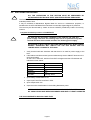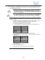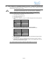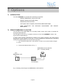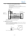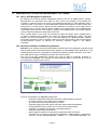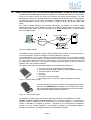
1
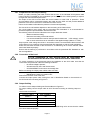
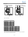
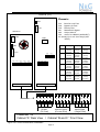
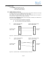
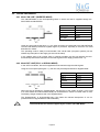
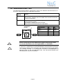
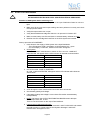
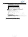
User Manual
POWERNET 33
3-phase UPS System
7.5 – 40 kVA
Cabinet A
Cabinet B
Cabinet C
CONTENTS
1
SAFETY ......................................................................................................................................................4
2
DESCRIPTION ............................................................................................................................................5
2.1
2.2
2.3
2.4
3
RELIABILITY AND QUALITY STANDARDS. .....................................................................................5
POWERNET MODELS – PARALLEL OPTION .............................................................................5
WARRANTY .......................................................................................................................................5
EXTENDED WARRANTY...................................................................................................................6
INSTALLATION ..........................................................................................................................................7
3.1
INTRODUCTION ................................................................................................................................7
3.1.1 Receipt of the UPS .........................................................................................................................7
3.1.2 Nameplate ......................................................................................................................................7
3.2
UNPACKING ......................................................................................................................................7
3.3
BATTERIES ........................................................................................................................................7
3.4
STORAGE ..........................................................................................................................................8
3.4.1 UPS ................................................................................................................................................8
3.4.2 Battery ............................................................................................................................................8
3.5
POSITIONING ....................................................................................................................................8
3.6
CABLING ............................................................................................................................................9
3.6.1 Connection Diagram.......................................................................................................................9
3.6.2 Preparation for the Input Cabling ...................................................................................................9
3.6.3 Earthing ..........................................................................................................................................9
3.6.4 Connection of the Mains Supply.....................................................................................................9
3.6.5 Single Input Feed ........................................................................................................................ 10
3.6.6 Dual Input Feed ........................................................................................................................... 10
3.6.7 Preparation for the Output Cabling.............................................................................................. 11
3.6.8 Connection of the Load ............................................................................................................... 11
3.6.9 Output Cabling............................................................................................................................. 11
3.7
INTERNAL BATTERY SYSTEMS ................................................................................................... 14
3.8
EXTERNAL BATTERY CABINET AND BATTERY CONNECTION
3.8.1 External Battery Configuration ............................................
3.8.2 Connection of External Battery Cabinet and UPS POWERNET Slim-Line ..................
3.9
INTERFACING ................................................................................................................................ 15
3.9.1 SMART PORT (Serial RS 232) ................................................................................................... 15
3.9.2 DRY PORT (volt-free contacts) ................................................................................................... 16
4
OPERATION ............................................................................................................................................ 17
4.1
COMMISSIONING ........................................................................................................................... 17
4.2
CONTROL PANEL. ......................................................................................................................... 17
4.2.1 Power Management Display (PMD) ............................................................................................ 17
4.2.2 LED Indicators ............................................................................................................................. 18
4.2.3 Keys............................................................................................................................................. 18
4.2.4 ON/OFF Start-up and Shutdown Buttons.................................................................................... 19
4.3
DESCRIPTION OF THE LCD.......................................................................................................... 20
4.3.1 Status Screens ............................................................................................................................ 20
4.3.2 Main Menu Screen ...................................................................................................................... 20
4.3.3 Event Log Screen ........................................................................................................................ 20
4.3.4 Measurements Screen ................................................................................................................ 20
4.3.5 Commands Screen...................................................................................................................... 21
4.3.6 UPS Data..................................................................................................................................... 21
4.3.7 Set-Up User................................................................................................................................. 22
4.3.8 Set-Up Service ............................................................................................................................ 22
Page 2
4.4
OPERATING MODES ..................................................................................................................... 23
4.4.1 Mode "ON LINE" (INVERTER MODE) ........................................................................................ 23
4.4.2 Mode"OFF-LINE"(ECO- or BYPASS MODE) ............................................................................. 23
4.4.3 "MAINTENANCE BYPASS" - Mode ............................................................................................ 24
4.5
START-UP PROCEDURE............................................................................................................... 25
4.6
SHUTDOWN PROCEDURE............................................................................................................ 27
4.7
LOAD TRANSFER: FROM INVERTER OPERATION TO MAINTENANCE BYPASS ................... 28
4.8
LOAD TRANSFER: FROM MAINTENANCE BYPASS TO INVERTER OPERATIONS ................. 29
5
MAINTENANCE ....................................................................................................................................... 30
5.1
5.2
5.3
5.4
6
TROUBLESHOOTING ............................................................................................................................. 31
6.1
6.2
6.3
7
INTRODUCTION ............................................................................................................................. 30
USER RESPONSIBILITIES............................................................................................................. 30
ROUTINE MAINTENANCE ............................................................................................................. 30
BATTERY TEST .............................................................................................................................. 30
ALARMS .......................................................................................................................................... 31
MENU, COMMANDS, EVENT LOG, MEASUREMENTS, .............................................................. 31
FAULT IDENTIFICATION AND RECTIFICATION .......................................................................... 31
OPTIONS ................................................................................................................................................. 32
7.1
INTRODUCTION ............................................................................................................................. 32
7.2
REMOTE EMERGENCY FACILITIES ............................................................................................. 32
7.3
REMOTE SIGNALLING PANEL (RSP) ........................................................................................... 33
7.3.1 How to Connect the Remote Signalling Panel (RSP) ................................................................. 34
7.4
GENERATOR ON FACILITIES ....................................................................................................... 34
7.5
WAVEMON SHUTDOWN AND MANAGEMENT SOFTWARE ...................................................... 35
7.5.1 Why is UPS Management important? ......................................................................................... 35
7.5.2 Wavemon Shutdown and Monitoring Software ........................................................................... 35
7.6
SNMP CARD/ADAPTER FOR NETWORK MANAGEMENT /REMOTE MONITORING ................ 37
8
TECHNICAL SPECIFICATIONS ............................................................................................................. 38
Page 3
1 Safety
BEFORE ATTEMPTING TO INSTALL OR START UP THIS UPS THE USER MUST
ENSURE THAT THE SAFETY INSTRUCTIONS IN THIS MANUAL ARE CAREFULLY
READ AND OBSERVED BY TECHNICALLY COMPETENT PERSONNEL. KEEP THIS
MANUAL WITH THE UPS FOR FUTURE REFERENCE.
THIS UPS MUST NOT BE STARTED UP OR PUT INTO USE WITHOUT HAVING BEEN
COMMISSIONED BY A FULLY TRAINED AND AUTHORISED PERSON.
!
ALL SERVICING MUST BE PERFORMED ONLY BY QUALIFIED PERSONNEL. DO
NOT ATTEMPT TO SERVICE THE UPS YOURSELF.
BY OPENING OR REMOVING THE UPS-COVERS YOU RUN RISK OF EXPOSURE TO
DANGEROUS VOLTAGES!
!
IN CASE OF ANY KIND OF DOUBT REGARDING THIS UPS, CONTACT:
NIGICO SA
Tel. 210-9855084
Fax. 210-9855094
e-mail: [email protected]
www.nigico.gr
HIGH LEAKAGE CURRENT!
MAKE SURE THAT THE EARTHING IS CARRIED OUT CORRECTLY BEFORE YOU
CONNECT THE MAINS POWER SUPPLY!
!
THE POWERNET 10 – 40 KVA IS CLASS A - UPS-PRODUCT (ACCORDING TO EN
50091/Part-2).
IN A DOMESTIC ENVIRONMENT IT MAY CAUSE RADIO INTERFERENCE. IN SUCH
AN ENVIRONMENT THE USER MAY BE REQUIRED TO UNDERTAKE ADDITIONAL
MEASURES.
!
!
USER MUST HANG A WARNING LABEL ON ALL PRIMARY UPS
POWER ISOLATORS. ELECTRICAL MAINTENANCE PERSONNEL SHOULD BE AWARE
OF DANGEROUS VOLTAGES. THE WARNING LABEL SHOULD CARRY THE
FOLLOWING WORDING:
“ISOLATE UPS BEFORE WORKING ON THIS CIRCUIT”
Page 4
2 Description
2.1 RELIABILITY AND QUALITY STANDARDS.
Congratulation on your purchase of the POWERNET 33.
The POWERNET 33 will provide your critical equipment with a steady and reliable power
supply for many years.
The unique and modular UPS POWERNET 33 belongs to the newest generation of midrange
3phase UPS-Systems. High reliability, low operating cost and excellent electrical performance
are only some of the highlights of this innovative UPS solution.
2.2 POWERNET 33 MODELS
The POWERNET UPS consists of: 7.5, 10, 15, 20, 30 and 40 kVA single models.
NOTE: POWERNET is not provided with the parallel feature.
2.3 WARRANTY
The POWERNET 33 is supplied with a limited warranty that the UPS and its component parts are
free from defects in materials for a period of 12 months from the date of original
commissioning or 15 months from the date of original delivery, whichever is the sooner.
Transportation cost is not included in the warranty and has to be paid by the end-user.
Do not return anything without written authorisation from NIGICO or your closest service centre.
NIGICO or the closest service centre will then give you further instructions how to proceed.
Any product must be returned with transportation charges prepaid and must be accompanied by
a description of the failure. Products without description will not be handled.
This warranty is invalidated if the UPS is put into use without having been commissioned by a
fully trained and by NIGICO authorised person.
This warranty does not apply to any damage or losses caused by misuse, abuse, negligence,
neglect, unauthorised repair or modification, incorrect installation, inappropriate environment,
accident, act of God or inappropriate application.
If the UPS fails to conform to the above within the warranty period then NIGICO SA or an
authorized service centre will, at its sole option, repair or replace the UPS or parts of it. All
repaired or replaced parts will remain the property of NIGICO or of the authorized service
centre.
NIGICO is not liable for any costs, such as loss of profits or revenue, loss of equipment, loss of
data or software, cost of substitutes, claims by third parties or otherwise.
As general policy, NIGICO does not recommend the use of any of its products in life support
applications where failure or malfunction of the NIGICO product can be reasonably expected to
cause failure of the life support device or to significantly affect us safety or effectiveness.
NIGICO does not recommend the use of any of its products in direct patient care. NIGICO will
Page 5
not knowingly sell its products for use in such applications unless it receives in writing
assurances satisfactory to NIGICO that the risks of injury or damage have been minimized, the
customer assumes all such risks and the liability of NIGICO is adequately protected under the
circumstances.
!
The UPS may contain batteries that must be re-charged for a minimum of 24 hours every
6 months to prevent deep discharging. Batteries that have been, for whatever reason, deep
discharged are not covered by the warranty.
2.4 EXTENDED WARRANTY
The standard warranty may be enhanced by protecting the UPS with an Extended Warranty
Agreement (maintenance contract).
For more details please contact the nearest representative.
Page 6
3 Installation
3.1 INTRODUCTION
This chapter contains all the necessary information for the correct unpacking, positioning, cabling
and installation of the UPS POWERNET 33.
ALL THE OPERATIONS IN THIS SECTION MUST BE PERFORMED BY
AUTHORISED ELECTRICIANS OR BY QUALIFIED PERSONNEL.
NIGICO will take no responsibility for any personal or material damage
caused by incorrect cabling or operations or activities, which are not carried
out as per the instructions contained in this manual.
!
3.1.1 Receipt of the UPS
Upon receiving the UPS, carefully examine the packing container and the UPS for any sign of
physical damage. In case of rupture or suspect inform immediately:
a) The carrier and
b) NIGICO SA.
Ensure that the received UPS corresponds to the material indicated in the delivery note.
The packing container of the POWERNET 33 protects it from mechanical and environmental
damage. To increase its protection the UPS is wrapped with a plastic sheet.
3.1.2 Nameplate
The technical specifications of the POWERNET 33 are provided on the nameplate, which is
situated at the front of the UPS. Check if it corresponds to the purchased material mentioned in
the delivery note.
3.2 UNPACKING
When unpacking the UPS observe the "FRAGILE" and "ARROW" on the packing container.
Perform the following steps to unpack the UPS:
Cut wrappers and remove packing container by pulling it upwards;
Remove the plastic cover from the UPS;
Remove pallet from the UPS;
Retain the packaging materials for future shipment of the UPS;
Examine the UPS for any sign of damage. Notify your carrier or supplier immediately if
damage is apparent.
3.3 BATTERIES
The standard batteries of the POWERNET are sealed, maintenance-free batteries, mounted in
UPS Cabinet.
The battery life depends very much on the ambient temperature. A temperature range between
+18° and +23°C will achieve the optimum battery life.
If the UPS is delivered without batteries, NIGICO is not responsible for any damage or
malfunctioning caused to the UPS by incorrect wiring.
Page 7
3.4 STORAGE
3.4.1 UPS
If you plan to store the UPS prior to use, keep the UPS unpacked in a dry, clean and cool storage
room with an ambient temperature between (+5 °C to +40°C) and humidity of less than 90%.
If the packing container is removed protect the UPS from dust.
3.4.2 Battery
The battery life depends very much on the ambient temperature.
It is therefore important not to store the battery longer than 6 months at 20°C, 3 months at 30°C
and 2 months at 35°C storage temperature without a battery recharge.
For longer-term storage make sure that the battery is fully recharged every 6 months.
SEALED BATTERIES MUST NEVER BE STORED IN A DISCHARGED OR PARTIALLY
DISCHARGED STATE.
EXTREME TEMPERATURE, UNDER- AND OVERCHARGE AND OVERDISCHARGE WILL
DESTROY BATTERIES!
Before and after storing, charge the battery.
Always store the batteries in a dry, clean, cool environment in their original packaging.
If the packing container is removed protect the batteries from dust and humidity.
3.5 POSITIONING
The POWERNET is a compact and light UPS and can easily be moved to the final position.
All parts of the POWERNET are accessible from the front and rear making it a service-friendly
and maintenance-friendly UPS.
The UPS should be located where:
Humidity and temperature are within prescribed limits;
Fire protection standards are respected;
Cabling can be performed easily;
Available front accessibility for service or periodic maintenance;
Requested air cooling flow should be granted;
The air conditioning system should have sufficient capacity;
Dust or corrosive/explosive gases must be absent;
The place is vibration free;
Minimum 10cm rear space is recommended for accessibility (see Figure 3.1 and 3.2);
Only front and rear access is necessary for service and maintenance.
Clearances
X
Clearances
X
X (Rear )
100mm
X (Rear )
100mm
Y (Right Side)
400mm
Y (Right Side)
400mm
X
X
Y
Y
Battery
Cabinet
UPS
UPS
Figure 3.2: UPS + Battery
cabinet space recommendation
Figure 3.1: UPS space recommendation
Page 8
3.6 CABLING
3.6.1 Connection Diagram
To ensure correct operation of the UPS and its ancillary equipment it is necessary to provide the
mains cables with appropriate fuse protection.
To connect the POWERNET to the mains power supply see Figures 3.3, 3.4 and 3.5.
ALL THE OPERATIONS IN THIS MANUAL MUST BE PERFORMED
BY AUTHORISED ELECTRICIANS OR BY QUALIFIED INTERNAL PERSONNEL.
DO NOT OPERATE IN CASE OF PRESENCE OF WATER OR MOISTURE.
!
BY OPENING OR REMOVING THE UPS-COVERS YOU RUN RISK OF EXPOSURE
TO DANGEROUS VOLTAGES!
3.6.2 Preparation for the Input Cabling
Before you start connecting the UPS, ensure that:
MAINS VOLTAGE (INPUT VOLTS) AND FREQUENCY (FREQUENCY)
CORRESPOND TO THE VALUES INDICATED ON THE NAMEPLATE OF THE UPS.
EARTHING IS PERFORMED IN ACCORDANCE WITH THE PRESCRIBED IEC
STANDARDS OR WITH LOCAL REGULATIONS;
UPS IS CONNECTED TO THE MAINS THROUGH A LV-DISTRIBUTION BOARD
WITH A SEPARATE MAINS LINE (PROTECTED WITH A CIRCUIT BREAKER OR
FUSE) FOR THE UPS.
Provide input fuses and cables according to Figure 3.4 or in accordance with the prescribed IEC
Standards or with the local regulations.
The input of the UPS must be fitted with circuit breakers or other kind of protection. The circuit
breakers will be connected between the mains supply and the UPS and will provide additional
protection to the UPS in the event of overloads and short circuits.
3.6.3 Earthing
!
ALL THE OPERATIONS IN THIS SECTION MUST BE PERFORMED BY
AUTHORISED ELECTRICIANS OR BY QUALIFIED TRAINED INTERNAL
PERSONNEL.
To ensure protection of personnel during the installation of UPS make sure that the connections
are performed under the following conditions:
No mains voltage is present;
Loads are shut down and disconnected;
UPS POWERNET is shut down and voltage-free.
Connect the earthing wire coming from the LV-Distribution Board to the terminal "PE".
Under the connection terminal of the UPS there is a cable-fixing rail to ensure that the cables
have been fastened properly.
3.6.4 Connection of the Mains Supply
After the UPS has been unpacked and brought to its final position the authorized technician may
start with the cabling.
!
ALL THE OPERATIONS IN THIS SECTION MUST BE PERFORMED BY
AUTHORISED ELECTRICIANS OR BY QUALIFIED INTERNAL PERSONNEL.
To ensure protection of the personnel during the installation of the UPS make sure that the
connections are performed under the following conditions:
No mains voltage is present;
All loads are shut down and disconnected;
UPS POWERNET is shut down and voltage-free.
Page 9
Remove the terminal cover of the UPS
Before connecting the input power cables make sure that:
UPS-System is placed in its correct position;
Maintenance Bypass IA1 is open in position OFF;
Connect the input power cable coming from the LV-Distribution Board to the terminals of the UPS
showed in the following pages, keeping the phase rotation in clock-wise sense.
!
NOTE: Neutral input wire must always be connected!
NOTE: The UPS POWERNET is provided with facilities for both single feed (one common
input cable for rectifier and bypass) and dual feed (separate input cable for rectifier and bypass).
The standard UPS POWERNET is always supplied with facilities for a single feed.
If dual feed is required please contact your nearest Service Centre.
3.6.5 Single Input Feed
To achieve correct Input Cabling see Drawing in Figure 3.5.
For single input feed connect the mains input cable to UPS Terminal Block according to the
following table:
MAINS INPUT CABLE
UPS TERMINAL
Phase L1
Phase L2
Phase L3
NEUTRAL
EARTH
1L1
1L2
1L3
1N
PE
For minimum recommended Input Cable Sections and Fuse Ratings for the POWERNET see
table in Figure 3.4.
Under the connection terminal of the UPS there is a cable-fixing rail to ensure that the cables
have been fastened properly.
3.6.6 Dual Input Feed
To achieve correct input cabling see Terminal Block in Figure 3.5.
NOTE:
The UPS is supplied (as standard version) with facilities for a single cable feed (for
rectifier and bypass).
If dual feed is required please contact your nearest Service Centre.
For dual input feed connect the mains input cables to UPS Terminal according to following
tables:
MAINS INPUT CABLE
UPS TERMINAL
BYPASS INPUT CABLE
Phase L1
Phase L2
Phase L3
NEUTRAL
EARTH
1L1
1L2
1L3
1N
PE
Phase L1
Phase L2
Phase L3
NEUTRAL
EARTH
UPS TERMINAL
2L1
2L2
2L3
2N
PE
For minimum recommended Input Cable Sections and Fuse Ratings for the POWERNET see
table in Figure 3.4.
Under the connection terminal of the UPS there is a cable-fixing rail to ensure that the cables
have been fastened properly.
Page 10
3.6.7 Preparation for the Output Cabling
Before you start connecting the loads, ensure that the sum of the indicated UPS-Systems rated
powers (OUTPUT POWER) on the nameplates (on the front side of the UPS-Systems) is equal to
or larger than the total load requirements.
The output of the UPS must be fitted with circuit breakers or other kind of protection. These
circuit breakers will be connected between the loads and the UPS and will provide additional
protection to the UPS in the event of overloads and short circuits.
These circuit breakers will enable the protection of each load separately.
The size of the circuit breakers depends on the load rating of the load sockets.
The circuit breakers must comply with the prescribed IEC Standards. It is recommended to
provide a separate output distribution board for the load.
The following values should be indicated on the output distribution board:
Maximum total load rating;
Maximum load rating of the load sockets.
If a common distribution board is used (sockets for Mains and UPS voltage), ensure
that on each socket there is an indication of the applied voltage (“Mains” or “UPS”).
Output power cable ratings should be in accordance with the recommended cable sections and
fuses ratings or in accordance with the prescribed IEC Standards or with the local regulations.
Under the connection terminal of the UPS there is a cable-fixing rail to ensure that the cables
have been fastened properly.
Ensure that the earthing is performed in accordance with the prescribed IEC Standards or with
the local regulations.
3.6.8 Connection of the Load
!
ALL THE OPERATIONS IN THIS SECTION MUST BE PERFORMED BY
AUTHORISED ELECTRICIANS OR BY QUALIFIED INTERNAL PERSONNEL
To ensure protection of the personnel during the installation of the UPS make sure that the
connections are performed under the following conditions:
No mains voltage is present;
All loads are shut down and disconnected;
UPS POWERNET is shut down and voltage-free.
Before connecting the output power cables make sure that:
UPS-Systems is fitted in its correct position;
Maintenance bypass is in position OFF;
Remove the terminal cover of the UPS.
Connect the output power cable coming from the LV-Distribution Board to the terminals of
the UPS as shown in drawing of Figure 3.5.
3.6.9 Output Cabling
To achieve correct Output Cabling see Terminal Block in Figure 3.5.
For output cabling connect output cable to UPS Terminal according to following Output to
UPS
terminal block correlation.
OUTPUT CABLE
UPS TERMINAL
Phase L1
Phase L2
Phase L3
NEUTRAL
EARTH
3L1
3L2
3L3
3N
PE
Under the connection terminal of the UPS there is a cable-fixing rail to ensure that the cables
have been fastened properly.
Page 11
Block Diagram
STANDARD VERSION (SINGLE INPUT FEED)
VERSION ON REQUEST (DUAL INPUT FEED)
MAINS (3x380V/220V,
3x400/230V,3x415/240
Fuse A
Cable A
Fuse C
Cable B
Cable C
FA2
FA1
FA3
Fuse B
FA2
FA1
Rectifier
FA3
Rectifier
Inverter
Inverter
Static Switch
Static Switch
IA2
IA2
PowerNet33
MAINS (3x380V/220V,
3x400/230V,3x415/240V
Mainten. Bypass IA1
PowerNet33
Mainten. Bypass IA1
Cable D
Cable D
Load
Load
Figure 3.3: Block Diagram
Cable sections and fuse ratings
Fuse A
(Agl/CB)
Cable A
(IEC 609501:2001)
Cable D
(IEC 609501:2001)
7.5
3x20
5x2.5
5x2.5
10
3x20
5x2.5
5x2.5
15
3x25
5x4
5x4
20
3x40
5x6
5x6
30
3x63
5x10
5x10
40
3x80
5x25
5x25
Power
(kVA)
Fuse B
(Agl/CB)
Cable B
(IEC 60950-1:2001)
Fuse C
(Agl/CB)
Cable C
(IEC 60950-1:2001)
Cable D
(IEC 60950-1:2001)
7.5
3x20
5x2.5
3x20
4x2.5
5x2.5
10
3x20
5x2.5
3x20
4x2.5
5x2.5
15
3x25
5x4
3x25
4x4
5x4
20
3x40
5x6
3x40
4x6
5x6
30
3x63
5x10
3x63
4x10
5x10
40
3x80
5x25
3x80
4x25
5x25
Power
(kVA)
Figure 3.4: Cable Sections and Fuse Ratings recommended by European standards for POWERNET
10-40kVA. Alternatively, local standards to be respected
Page 12
Cabinet B (or C)
Elements:
JD1
FA1
Rectifier Line Fuse
FA2
Bypass Line Fuse
FA3
Battery Fuse
IA1
Maintenance Bypass
IA2
Output Switch
JD1
Smart Port-RS232 (SUB-D9P/F)
X1-X21 Dry Port-volt-free relays (SUBD25/F)
X1-X21
Cabinet A
SNMP
SNMP
JD1
7,5kVA
X1-X21
FA2
FA1
10kVA
15kVA
IA1
IA2
FA3
FA2
FA1
IA1
IA2
FA3
20kVA
30kVA
40kVA
In/Output Terminal Block
FA1 (A)
FA2 (A)
FA3 (A)
16 A
(10x38)
ultrafast
16 A
(10x38)
ultrafast
30 A
(10x38)
ultrafast
30 A
(10x38)
ultrafast
50 A
(14x51)
ultrafast
63 A
(22x58)
ultrafast
16 A
(10x38)
GL/GC
30 A
(10x38)
ultrafast
30 A
(10x38)
ultrafast
50 A
(14x51)
ultrafast
50 A
(14x51)
ultrafast
63 A
(22x58)
ultrafast
80 A
(22x58)
ultrafast
16 A
(10x38)
GL/GC
32 A
(10x38)
GL/GC
30 A
(10x38)
GL/GC
50 A
(14x51)
GL/GC
63 A
(22x58)
GL/GC
In/Output Terminal Block
3L1 3L2 3L3
3N
PE
Output
(To Load)
PE
2L1 2L2 2L3
Separate Bypass
(For Dual Feed)
2N
1N
1L1 1L2 1L3
Mains Input
(Single Feed)
PowerNet 33
Cabinet “A” Rear View / Cabinet “B and C ” Front View
Figure 3.5.1: In/Out Terminal Block, POWERNET
Page 13
PE
3.7 INTERNAL BATTERY SYSTEMS
POWERNET 33 is available in thee types of Cabinets:
Cabinet A: For POWERNET 7.5-15kVA with a maximum of 50 x 7Ah or 9Ah batteries
Cabinet B: For POWERNET 7.5-40kVA with a maximum of 144 x 7Ah or 9Ah batteries
Cabinet C: For POWERNET 7.5-40kVA with a maximum of 80 x 24Ah or 28Ah batteries
External battery cabinets are not foreseen for the POWERNET 33.
Page 14
3.8 INTERFACING
The POWERNET is provided with two ports:
SMART PORT (Serial RS 232);
DRY PORT (volt-free contacts);
3.8.1 SMART PORT (Serial RS 232)
The SMART PORT JD1 is an intelligent RS 232 serial port that allows the UPS to be connected
to a computer. The connector is a standard D-Type, 9-pin, female.
When installed the optional SMART PORT, the software WAVEMON allows the computer to
monitor the mains voltage and the UPS status continuously.
In the event of any changes the computer terminal will display a message. (For details see our
Monitoring Package: WAVEMON )*.
The Fig. 3.8 and 3.9 shows how to connect a PC to the UPS.
a)
a)
Fig. 3.8 in case the PC has a 9 pin serial port
b)
Fig. 3.9 in case the PC has a 25 pin serial port
Interface Cable (UPS End)
(9-Pin, D-Type Male)
Connects to UPS
SMART PORT
Interface cable (Computer End)
(9-Pin, D-Type Female)
1
1
2
2
3
3
5
5
Connects to
Computer
.
.
.
.
.
.
9
9
Figure 3.8 Connector Cable - PC Serial Port with 9-Pin Connection
b)
Interface Cable (UPS End)
(9-Pin, D-Type Male)
Connects to UPS
SMART PORT
Interface cable (Computer End)
(25-Pin, D-Type Female)
1
1
2
2
3
3
.
.
.
5
.
.
.
7
.
.
.
.
9
25
Figure 3.9 Connector Cable – PC Serial Port with 25-pin Connection
Page 15
Connects to
Computer
3.8.2 DRY PORT (volt-free contacts)
Description:
The DRY PORT JD2 (DB-25P/F) may be used for:
Connection of remote emergency stop facilities (see paragraph 9.2);
Connection of Remote Status Panel (see paragraph 9.3);
Provision of signals for the automatic and orderly shutdown of servers
or IBM AS400, etc.
Definition of PINs on DRY PORT JD2 (25 PIN):
Pin
Contact
Signal
Function
1
NO
2
NC
3
C
Common
4
NO
Load on inverter
5
NC
6
C
Common
7
NO
Battery low
8
NC
9
C
Common
10
NO
Load on Mains (BYPASS mode)
11
NC
12
C
Common
13
NO
Common Alarm
14
NC
15
C
Mains failure
ALARM
Message
ALARM
Message
ALARM
MAINS_OK
Mains present
LOAD_ON_INV
BATT_LOW
Battery OK
LOAD_ON_MAINS
COMMON_ALARM
No Alarm Condition
Common
16
-
NC
Not Connected
19
20
Customer in
21
GND
Customer in GND
22
PS_12
GND
23
PS_12
+ 12V (Imax = 100 mA)
24
Not Connected
25
Not Connected
All volt free contacts are rated 60 VAC max. and 500 mA max.
Figure 3.10
DRY PORT (JD2) Connections
Page 16
+12V
4 Operation
4.1 COMMISSIONING
The POWERNET UPS is a high quality electronic machine that must be commissioned by a fully
trained and authorized NIGICO field service engineer before being put into use.
The commissioning of the UPS involves the connection of the UPS and battery, the checking of
the electrical installation and operating environment of the UPS, the controlled start-up and
testing of the UPS and customer training.
!
Any POWERNET UPS system not commissioned by a NIGICO field
service engineer or authorized service centre must be considered an
electrical hazard and NIGICO accepts no responsibility for its safe operation or
the safety of any personnel. Additionally, the manufacturer’s warranty is
immediately invalidated if the UPS is put into use before it has been correctly
commissioned.
4.2 CONTROL PANEL
The user-friendly control panel is composed of three parts:
POWER MANAGEMENT LCD DISPLAY (PMD);
LED INDICATORS;
KEYS.
PowerNet
Line 2
Bypass
ON/OFF
Line 1
Inverter
ON/OFF
Battery
RESET
Alarm
µ
¶
ENTER
Figure 4.1 Control Panel.
4.2.1 Power Management Display (PMD)
The 2 x 20 character LCD simplifies the communication with the UPS and provides the
necessary monitoring information about the UPS.
The menu driven LCD enables the access to the:
EVENT REGISTER;
Monitor the input and output U, I, f, P,
Battery runtime;
To perform commands like start-up and shut-down of UPS and
Load transfer from INVERTER to BYPASS and vice-versa;
DIAGNOSIS (SERVICE MODE);
Adjustments and testing.
Page 17
4.2.2 LED Indicators
The mimic diagram serves to indicate the general status of the UPS. The LED-indicators show
the power flow status and in the event of mains failure or load transfer from inverter to bypass
and vice-versa. The corresponding LED-indicators will change colours from green (normal) to red
(warning).
The LED’s LINE 1 (rectifier) and LINE 2 (bypass) indicate the availability of the mains power
supply.
The LED’s INVERTER and BYPASS if green indicate which of the two is supplying power to the
critical load. When the battery is supplying the load due to mains failure the LED-indicator
BATTERY is flashing.
The LED-indicator ALARM is a visual indication of any internal or external alarm condition. At the
same time an audible alarm will be activated.
INDICATOR
INDICATOR STATUS
MEANING
ALARM
OFF
No alarm condition
RED
Alarm condition
LINE 1
LINE 2
BY-PASS
INV
BATTERY
GREEN
Mains rectifier available
RED
Mains rectifier not available
GREEN
Mains bypass available
RED
Mains bypass not OK or not available
OFF
GREEN
UPS is turned off
Load on bypass (Bypass-or Eco-Mode)
OFF
Bypass not operating (switched-off)
GREEN
Load on inverter
RED
Inverter fault or load not transferable to inverter
OFF
Inverter not operating (switched-off)
GREEN
Battery OK
RED
Battery fault or battery is discharged
Flashing GREEN
Battery in discharge or battery fuse open
4.2.3 Keys
The keys allow the user to operate the UPS to perform settings and adjustments, to start-up and
shutdown the UPS, to monitor on the LCD display the voltages, currents, frequencies and other
values.
KEYS
FUNCTION
ON/OFF
Serve to switch-on (press both keys simultaneously), or shutdown the UPS (press both keys
simultaneously)
ON/OFF
UP (µ)
Move upwards through the menu
DOWN (¶)
Move downwards through the menu.
RESET
Cancel the audible alarm. If the alarm condition was only transient the LED-indicator
ALARM would also extinguish otherwise it will remain on (red).
ENTER
Confirms a chosen menu item.
Page 18
4.2.4 ON/OFF Start-up and Shutdown Buttons
By pressing simultaneously both ON/OFF Buttons on the Control Panel the UPS may be
switched on or shutdown. This is to prevent accidental start-up or shutdown of the UPS. The two
main ON/OFF buttons are also used as a security LOAD–OFF-switch, making it possible to
quickly disconnect the load from the UPS in emergency situations when a competent technician
working on the UPS is in danger or if the UPS has some kind of anomaly.
!
!
TO SHUT DO WN A UPS-SYSTEM YOU MUST PRESS BOTH ON/OFF-BUTTONS
SIMULTANEOUSLY ON CONTROL PANEL!
ACTIVATION OF THE ON/OFF BUTTONS WHEN THE UPS IS NOT
IN MAINTENANCE BYPASS MODE WILL INTERRUPT THE POWER SUPPLY TO
THE LOAD.
LOAD OFF on POWERNET
If, for security or emergency reasons, it is necessary to immediately disconnect the load from the
UPS, press the two red ON/OFF Buttons simultaneously. This is to avoid any accidental
manipulation.
Page 19
4.3 DESCRIPTION OF THE LCD
4.3.1 Status Screens
DESCRIPTION
LCD-DISPLAY
1
Load is protected by UPS power (load is supplied
by inverter(Normal Operation)
LOAD
PROTECTED
2
Load is not protected by UPS power it is supplied
by mains power (load on bypass)
3
Load supply completely interrupted. UPS has been
switched off by “ON/OFF” buttons
LOAD
NOT PROTECTED
LOAD OFF
SUPPLY FAILURE
4.3.2 Main Menu Screen
DESCRIPTION
LCD-DISPLAY
1
Logging Control. A log of the last 64 events is
stored in the Power Management Display.
¬ EVENT LOG
MEASUREMENTS
2
In Menu Measurements: monitor voltages,
power,frequencies, currents, autonomy etc.
¬ MEASUREMENTS
COMMANDS
3
The Command Menu enables to perform the
commands “Load to inveter”, Load to bypass,
battery test.
¬ COMMANDS
UPS DATA
4
The UPS Data are the UPS personalized
information “serial number”
¬ SET-UP DATA
SET-UP USER
5
Various settings can be performed by the user:
Date/Time, automatic battery test, etc.
¬ SET-UP USER
SET-UP SERVICE
6
Various adjustments can be performed by the
service staff
¬ SET-UP SERVICE
NO MORE MENU
4.3.3 Event Log Screen
DESCRIPTION
LCD-DISPLAY
01
05-10-00
LOAD TO INV.
02
05-10-00
LOAD TO BYP.
1
Logging Control; a log of the last 64 events is
stored in the Power Management Display.
2
Every stored event is identified with a sequential
number and time stamp.
3
All events and alarms are indicated with their date 03
05-10-00
and time of appearance.
LOAD OFF
14-38-59
14-38-56
14-37-14
4.3.4 Measurements Screen
DESCRIPTION
LCD-DISPLAY
1
Battery Runtime
BATT. RUN TIME (MIN)
00h 00m
2
UPS-Output Frequency
OUTPUT FREQUENCY (HZ)
50.00
3
Bypass Frequency.
BYPASS FREQUENCY (HZ)
50.00
Page 20
4
Battery Voltage
BATTERY VOLTAGE (V)
+ 0.0
- 0.0
5
Battery Charger Current
BATT. CHARGE CUR. (A)
+ 0.0
- 0.0
6
Discharge Current.
DISCHARGE CURRENT (A)
00.00
7
Rectifier Voltage of all three phases
RECTIFIER VOLTAGE (V)
230
230
230
8
Bypass Voltage of all three phases
BYPASS VOLTAGE (V)
230
230
230
9
Output Voltage of all three phases
OUTPUT VOLTAGE (V)
230
230
230
10 Output Current of all three phases
OUTPUT CURRENT (A)
00.00
00.00
00.00
11 Active Output Power of all three phases
ACTIVE POWER (KW)
00.00
00.00
00.00
12 Reactive Output Power of all three phases
REACTIVE POWER (kVAr)
00.00
00.00
00.00
13 Apparent Output Power of all three phases
APPARENT POWER (KVA)
00.00
00.00
00.00
14 Output Power of all three phases
OUTPUT POWER (%)
00.00
00.00
00.00
15 Battery capacity
BATT. CAPACITY (%)
00.00
4.3.5 Commands Screen
DESCRIPTION
LCD-DISPLAY
1 Transfer Load to inverter
¬ LOAD TO INVERTER
LOAD TO BYPASS
2 Transfer Load to bypass.
¬ LOAD TO BYPASS
PERFORM BATT.TEST
3 Battery Test
¬ PERFORM BATT.TEST
NO MORE COMMANDS
4.3.6 UPS Data
DESCRIPTION
LCD-DISPLAY
1 These general UPS Data are installed at the
manufacturing plant
UPS SERIAL NUMBER
NW-nnnnn
DATE OF MANUFACTURE
15-01-2003
2 Manufacturing date
3 EPROM Version
EPROM VERSION
V-000
4 Dynamic Password
YES
5 Actual Date and Time
DATE
dd-mm-yyyy
Page 21
NO
TIME
hh:mm:ss
4.3.7 Set-Up User
DESCRIPTION
LCD-DISPLAY
1 Set-up Language
¬ SET LANGUAGE
SET DATE AND TIME
ENGLISH
FRENCH
SPANISH
GERMAN
POLISH
2 Set-up Date and Time
¬ SET-UP DATE AND TIME
SET-UP BATT.
TEST
DD-MM-YY HH-MM-SS
3 Set-up battery test
¬SET BATTERY TEST
SET GENERATOR OP.
DAY OF MONTH
(1-31)
HOUR OF DAY
(1-24)
REPETITIVE (Y/N)
YES/NO
4 Set-up operation with Gen-Set
¬ SET GENERATOR OP.
NO MORE SETTINGSETTINGS
BATT.CHARGE LOCK
YES/NO
BYPASS LOCK
YES/NO
4.3.8 Set-Up Service
DESCRIPTION
LCD-DISPLAY
1 This Menu is reserved for authorized service
¬ SET-UP SERVICE
PASSWORD
2 Type in password
¬ PASSWORD
engineers. It is not to be used by End-Users
Password is necessary to enter.
NOTE:
Apart from the adjustment of voltages, frequencies, currents, power and autonomies
in the SET-UP Service it is also possible to set and check the following parameters:
UPS Rated Power
Single (standard) or Dual Input feed
f-converter, 50/60Hz and 60/50Hz
Sync window (2-4%)
Page 22
4.4 OPERATING MODES
4.4.1 Mode "ON LINE" (INVERTER MODE)
The ON-LINE-Mode is the UPS-Operating Mode in which the load is supplied through the
RECTIFIER and INVERTER.
LED Indicator
LINE 1
LINE 2
BYPASS
INVERTER
BATTERY
Colour
Green
Green
OFF
Green
Green
Using the control panel (see figure 4.1), the UPS can easily be transferred to the ON-LINE-Mode.
The ON-LINE-Mode provides the highest degree of protection, especially in the event of a mains
disturbance or failure.
This operating mode is always recommended if the critical loads (computer systems) will not
tolerate any interruption of the supply (not even the shortest).
In the unlikely event of an inverter fault or overload condition the UPS will transfer the load
automatically and without interruption to the static bypass-mains supply (transfer time = 0).
4.4.2 Mode"OFF-LINE"(ECO- or BYPASS MODE)
In the "OFF-Line Mode”, the load is supplied from the mains through the static bypass.
Using the control panel (see figure 4.1), the UPS may be easily transferred to "Bypass Mode”.
LED Indicator
LINE 1
LINE 2
BYPASS
INVERTER
BATTERY
Colour
Green
Green
Green
OFF
Green
When the UPS is operating in "Bypass Mode”, the efficiency of the system is higher. In the event
of a mains failure the load will automatically be transferred from mains to inverter within 5 msec.
The battery charger remains active in the "Bypass-Mode”.
The "Bypass-Mode”, is recommended only if the loads can tolerate interruptions of 3-5 ms
(transfer time from Bypass Mode to ON-LINE Mode).
!
In order to provide the load with maximum protection NIGICO always
recommends that the load be supplied by the inverter (ON-LINE-Mode).
Page 23
4.4.3 "MAINTENANCE BYPASS" - Mode
The Maintenance Bypass Mode is performed by means of the MANUAL BYPASS SWITCH on
the rear for cabinet A and front for cabinet B/C of the UPS:
POSITION OF
EFFECT
SWITCH
ON
Bypass-Switch Closed (Load supplied directly from mains)
LCD-indication: “MANUAL BYP IS CLOSED” LED Indicators will indicate
as shown in table below.
OFF
Bypass-Switch Open - Normal Operating Condition
(Load supplied by inverter)
LCD-indication “MANUAL BYPASS IS OPEN”
LED Indicators will indicate as shown in table below.
MAINTENANCE
BYPASS
MAINS
LOAD
LED Indicator
LINE 1
LINE 2
BYPASS
INVERTER
BATTERY
ON
Green
Green
Green
RED
Green
OFF
Green
Green
Green
OFF
Green
UPS
!
!
Before transferring the load to Maintenance Bypass switch always make
sure all the UPS-modules are in the "Bypass-Mode” or “ECO-Mode”.
IF THE UPS IS OPERATING IN THE MAINTENANCE BYPASS MODE THROUGH
THE BYPASS SWITCH THE LOAD WILL NOT BE PROTECTED IN THE EVENT
OF A MAINS FAILURE. IT IS THEREFORE STRONGLY RECOMMENDED TO
SWITCH OVER TO THE ON-LINE MODE (INV. ON) OR BYPASS MODE (OFFLINE MODE) AS SOON AS POSSIBLE.
Page 24
4.5 START-UP PROCEDURE
!
ALL THE OPERATIONS IN THIS SECTION MUST BE PERFORMED BY
AUTHORISED ELECTRICIANS OR BY QUALIFIED INTERNAL PERSONNEL.
Situation of UPS-System before switching it on:
1. The fuses for the supply of UPS-System in the Input Distribution Board on site are
open.
2. Make sure all the input and output cabling has been performed correctly and check
the input phase rotation.
3. Verify that output switch IA2 is open
4. Verify that the Maintenance Bypass Switch IA1 is open and in Position OFF.
5. Make sure the battery fuse FA3 and those in external battery cabinets are open.
6. Rectifier fuse FA1 and Bypass fuses FA2 on the UPS-System are inserted.
Start up procedure of POWERNET:
1. Insert fuses for the supply of UPS-System in the Input Distribution
- The LED-indicators LINE 1 and battery on UPS-Systems is lit – green
- On LCD-Display “LOAD OFF, SUPPLY FAILURE” will appear.
2. UPS-System :
Press both “ON/OFF” Main Buttons to switch on UPS. On LCD: “LOAD NOT
PROTECTED” will appear and the LED-indicator will indicate as shown bellow:
LED Indicator
LINE 1
LINE 2
BYPASS
INVERTER
BATTERY
Colour
Green
Green
Green
OFF
Flashing Green
3. Check Command: LOAD TO INVERTER
On LCD: “LOAD PROTECTED” will appear and the LED-indicator will indicate as
shown below:
LED Indicator
LINE 1
LINE 2
BYPASS
INVERTER
BATTERY
Colour
Green
Green
OFF
Green
Flashing Green
4. Scroll through the menu measurement and check their correctness.
5. Check battery polarity and voltage.
6. If the battery polarity and voltage is correct insert FA3 and/or external battery
fuses(breakers).
7. NOTE: The fuses in the OUTPUT DISTRIBUTION BOARD remain still open.
Close output switch IA2 in UPS
There is now UPS Power on the output Terminal Block.
8. Load transfer to Maintenance Bypass
Go to Menu COMMANDS and choose command “LOAD TO BYPASS” and transfer
the load to mains on control panel of UPS-System. Message “LOAD NOT
PROTECTED” will appear on LCD.
Page 25
Close Maintenance Bypass Switch IA1 (position ON)
On LCD: “MANUAL BYPASS IS CLOSED” will appear and the LED-indicator will indicate
as shown bellow:
LED Indicator
LINE 1
LINE 2
BYPASS
INVERTER
BATTERY
Colour
Green
Green
Green
RED
Green
NOTE: Your UPS in now on manual bypass and the load is not protected
9. Connect Load to the UPS Output
Insert fuses in output Distribution Board
Verify on control Panel that the load is on bypass”
10. Open Maintenance Bypass Switch IA1
On LCD: “MANUAL BYP IS OPEN” will appear followed by
“LOAD NOT PROTECTED”
11. Check on LCD the Output Powers, Voltages Currents and Frequencies.
12. Load transfer to Inverter
Go to Menu COMMANDS and choose command “LOAD TO INVERTER” and transfer
the load to inverter on control panel of UPS-System.
On LCD: “LOAD PROTECTED” will appear.
13. Check the output Voltages and Currents once again.
THE LOAD IS NOW PROTECTED BY THE UPS POWERNET
Page 26
4.6 SHUTDOWN PROCEDURE
!
ALL THE OPERATIONS IN THIS SECTION MUST BE PERFORMED BY
AUTHORISED ELECTRICIANS OR BY QUALIFIED INTERNAL PERSONNEL.
The POWERNET UPS may be shutdown completely if the load does not need input power for an
extended period of time.
It may be switched to Maintenance Bypass Mode for service or maintenance purposes, or
transferred to the OFF-LINE Mode if the load does not need the highest degree of protection.
The load may be disconnected by means of the two ON/OFF (LOAD-OFF) buttons for security
reasons.
Complete Shutdown procedure of POWERNET:
!
The UPS may be shut down completely if the loads do not need any
power supply. Therefore the following steps are to be performed only after
the load has been disconnected and does not need any power supply.
ACTIVATION OF BOTH ON/OFF BUTTONS SIMULTANEOUSLY WHEN DURING
NORMAL OPERATION WILL SWITCH OFF THE UPS OUTPUT AND NO
LONGER SUPPLY POWER TO THE LOAD.
1. Verify that the loads are shutdown and that there is no need for power supply to the
load.
2. If the loads are all disconnected, press simultaneously the two ON/OFF buttons on the
UPS-control panel.
On the LCD: “LOAD OFF, SUPPLY FAILURE” will appear and the LED-indicator will
indicate as shown below:
LED Indicator
LINE 1
Colour
Green
LINE 2
BYPASS
INVERTER
BATTERY
OFF
OFF
OFF
Flashing Green
3. Open battery fuses/breakers FA3
4. Open Input Fuses FA1 and FA2 in UPS.
5. Open Output switch IA2
6. Open the mains fuses/breaker in the building distribution panel.
AFTER SWITCHING OFF A UPS UNIT MAKE SURE THE INTERNAL
DC- CAPACITORS HAVE BEEN DISCHARGED AND WAIT AT LEAST 10 MINUTES
THE UPS POWERNET IS NOW VOLTAGE FREE.
Page 27
4.7 LOAD TRANSFER: FROM INVERTER OPERATION TO MAINTENANCE BYPASS
If it is necessary to perform service or maintenance on the UPS it is possible to transfer the
UPS to MAINTENANCE BYPASS.
!
BEFORE YOU SWITCH THE MAINTENANCE BYPASS TO POSITION
«ON», MAKE SURE THAT THE LOAD HAS BEEN TRANSFERRED TO MAINS
SUPPLY (OFF-LINE MODE)
ALL THE OPERATIONS IN THIS SECTION MUST BE PERFORMED BY
!
AUTHORISED ELECTRICIANS OR BY QUALIFIED INTERNAL PERSONNEL.
Situation of UPS-System before starting the Transfer Procedure to Maintenance Bypass:
The load is protected by POWERNET UPS running in normal operation. The UPS system is
operating on inverter.
1. Using LDC panel, select the COMMANDS menu and choose command “LOAD TO
BYPASS”. This will transfer the LOAD to mains on the complete system.
On LCD panel “LOAD NOT PROTECTED” will appear.
2. Close Maintenance Bypass Switch IA1 (position ON).
On LCD: “MANUAL BYP IS CLOSED” will appear and the mimic panel will show:
LED Indicator
LINE 1
LINE 2
BYPASS
INVERTER
BATTERY
Colour
Green
Green
Green
RED
Green
3. Press simultaneously both ON/OFF buttons on UPS-control panel.
On the LCD’s message “LOAD OFF, SUPPLY FAILURE” will appear and the mimic
panel will show:
LED Indicator
LINE 1
Colour
Green
LINE 2
BYPASS
INVERTER
BATTERY
OFF
OFF
OFF
Green
4. Open output switch IA2
5. Open battery fuses/breakers FA3
6. Open input fuses FA1 and FA2 so that the UPS is voltage-free.
THE LOAD IS NOW SUPPLIED BY MAINS AND IS NOT PROTECTED
Page 28
4.8
LOAD TRANSFER: FROM MAINTENANCE BYPASS TO INVERTER OPERATIONS
This procedure describes the sequence of operations to be done in order to restart the UPS and
restore ON-LINE mode (Load on Inverter).
ALL THE OPERATIONS IN THIS SECTION MUST BE PERFORMED BY
AUTHORISED ELECTRICIANS OR BY QUALIFIED INTERNAL PERSONNEL.
!
Situation of UPS-System before starting the Transfer Procedure to ON-LINE mode:
The load is supplied directly by Input Mains power and the UPS is OFF.
1.
2.
3.
4.
Close Input fuses FA1 and FA2.
Close battery fuses/breakers FA3
Close output switch IA2.
On the LCD’s: “LOAD OFF, SUPPLY FAILURE” will appear and the mimic panel will
show:
LED Indicator
LINE 1
Color
Green
LINE 2
BYPASS
INVERTER
BATTERY
OFF
OFF
OFF
Flashing/Green
5. Press simultaneously both ON/OFF buttons on UPS-control panel.
Unit will start-up and after about 60 seconds the mimic panel will show:
LED Indicator
LINE 1
Color
Green
LINE 2
BYPASS
INVERTER
BATTERY
Green
Green
RED
Green
6. Make sure that the bypass LED is green, then open the Maintenance Bypass Switch
IA1 (position OFF).
7. Using LDC panel, select the COMMANDS menu and choose command “LOAD TO
INVERTER”. This will transfer the LOAD to Inverter on the complete system. On LCD
panel “LOAD PROTECTED” will appear.
THE LOAD IS NOW SUPPLIED BY INVERTER POWER AND IS PROTECTED
Page 29
5 Maintenance
5.1 INTRODUCTION
!
ALL THE OPERATIONS IN THIS SECTION MUST BE PERFORMED BY
AUTHORISED ELECTRICIANS OR BY QUALIFIED INTERNAL PERSONNEL.
To ensure an optimum operation of the POWERNET and a continuous and efficient protection of
the connected load it is recommended to check the batteries every 6 months, depending on the
ambiance temperature.
5.2 USER RESPONSIBILITIES
There are no user serviceable parts contained within the UPS so the maintenance responsibilities
of the user are minimal. To maximise the useful working life and reliability of the UPS and its
batteries, the environment in which the UPS operates should be kept cool, dry, dust and vibration
free. The batteries should be hold fully charged.
5.3 ROUTINE MAINTENANCE
The UPS is designed to receive regular preventative maintenance inspections. These
preventative maintenance inspections are essential to ensure that both the useful working life and
the reliability of the UPS are maximised. When the UPS is commissioned, the commissioning
field service engineer will attach a service record book to the front of the UPS and this will be
used to record the full service history of the UPS.
Preventative maintenance inspections involve working inside the UPS, which contains hazardous
AC and DC voltages. Only NIGICO trained or agreed service personnel and authorised field
service engineers are fully aware of all of the hazardous areas within the UPS.
During a preventative maintenance inspection the field service engineer will carry out the
following checks:
Site/environment conditions;
Integrity of electrical installation;
Cooling airflow;
Rectifier operation and calibration;
Inverter operation and calibration;
Static switch operation;
Battery status;
Load characteristics;
Integrity of alarm and monitoring systems;
Operation of all installed options;
5.4 BATTERY TEST
The battery test takes approx. 3 minutes and should be performed only if:
there are no alarm conditions;
the battery is fully charged;
mains is present.
The battery testing can be carried out independently of the operation mode (OFF-LINE or ONLINE) and whether or not the load is connected.
The battery test procedure can be performed from the UPS front panel. See “Operation” Chapter 4.
Page 30
6 Troubleshooting
6.1 ALARMS
In the event of an alarm condition the red LED-Indicator “Alarm” and the audible alarm will turn
on.
In this case proceed as follows:
1. Silence the audible alarm by pressing the button "Reset".
2. Identify the cause of the alarm condition by means of the EVENT LOG in the MAIN
menu.
3. In case of doubts please contact the nearest Service centre.
4. Fault identification and rectification information is given on the following pages.
6.2 MENU, COMMANDS, EVENT LOG, MEASUREMENTS,
In Chapter 4 there is a detailed description of the Menu, Commands, Event Log and
Measurements that can be operated and displayed on the LCD. The List of Alarms and
Messages are shown in the Annexe.
6.3 FAULT IDENTIFICATION AND RECTIFICATION
The major alarm conditions that will be encountered are:
Alarm Condition
Meaning
Suggested Solution
UPS FAULT
There is a fault in the UPS and therefore
Call the authorised service centre for assistance
normal operation cannot be guaranteed
MAINS BYP/RECT
FAULT
OUTPUT SHORT
Mains power supply is outside
prescribed tolerance
There is a short circuit at the output of
UPS (on load side)
OVERLOAD
OVERTEMPERATURE
Load exceeds the UPS rated power
UPS temperature has exceeded the
allowed value
BATTERY CHARGER OFF
INVERTER FAULT
SYNCHRON FAULT
The attached battery and the battery
charger set-up do not correspond or
battery charger fault
breakers etc. supplying the UPS
Check all output connections and repair as
required.
Identify which piece of equipment is causing the
overload and remove it from the UPS. Do not
connect laser printers, photocopiers, electric
heaters, kettles etc. to the UPS
Check the ambient temperature of the UPS is less
than 30° C.
If the ambient temperature is normal call the
authorised service centre for assistance.
Call the authorised service centre for
assistance.
Call the authorised service centre for assistance.
Inverter is faulty.
The inverter and mains are not
synchronised.
BATTERY IN
DISCHARGE
MANUAL BYPASS IS
CLOSED
The input power to UPS is too low or missing.
If site power appears to be OK, check the input circuit
The frequency of the input voltage to the UPS is
outside operational limits and the UPS static bypass
has been temporarily disabled.
Battery is near end of autonomy
Shutdown load connected to UPS before the
UPS switches itself off to protect its batteries
Maintenance Bypass closed. Load
supplied by mains
This alarm is only displayed if the UPS is on
Maintenance Bypass
Page 31
7 Options
7.1 INTRODUCTION
The UPS POWERNET is provided with the following accessories:
REMOTE EMERGENCY STOP FACILITIES;
REMOTE SIGNALLING PANEL (RSP);
GENERATOR ON FACILITIES;
SOFTWARE FOR AUTOMATIC SHUTDOWN AND MONITORING;
SNMP INTERFACES
MONITORING.
FOR
NETWORK
MANAGEMENT
AND
REMOTE
7.2 REMOTE EMERGENCY FACILITIES
The emergency stop facility must use a normally closed contact, which opens to operate the
emergency stop sequence.
The emergency stop port X1 is located at the front of the UPS POWERNET module. See
Figure 3.5 for location drawing.
In order to allow removal, maintenance or testing of any remote emergency stop facility without
disturbing the normal operation of the UPS, it is recommended that a terminal block, with linking
facilities, be installed between the UPS and the stop button.
1. Use a screened cable with 1 pair (section of wires 0.6 mm2) and maximum length
of 100 m.
2. Connect the cable as shown in Fig. 7.1
EMERGENCY STOP SWITCH
(N.C. = Normally Closed)
UPS
EMERGENCY OFF
(X1)
Terminal Block
Fig 7.1 Drawing of the wiring for the EMERGENCY-OFF-SWITCH.
Page 32
7.3 REMOTE SIGNALLING PANEL (RSP)
The optional Remote Status Panel (RSP) may be used to display UPS status information up to a
distance of 100m.
INV
LINE
(1)
(3)
LOAD
(2)
BATT.
(1)
(4)
(7)
LINE
BYPASS
(5)
(6)
Remote Signalling Panel
No.
1
2
3
4
INDICATOR
INDICATOR STATUS
MEANING
LINE
GREEN
Mains available
RED
Mains not available
GREEN
Battery OK
YELLOW
Battery near the end of capacity
OFF
No UPS supply or UPS on bypass
GREEN
Load supplied by inverter
OFF
Inverter supply not available
GREEN
Load is supplied
RED FLASHING
Load is not supplied
BATTERY
INVERTER
LOAD
5
ALARM RESET
Push button
Silence the audible alarm
6
ALARM
RED
Alarm condition; check other LEDS for
indication of mains and/or UPS status.
UPS is in normal operation condition
OFF
7
BYPASS
RED
OFF
Load is supplied by mains
Load is supplied by inverter
Figure. 7.2: LED Indicators on Remote Signalling Panel (RSP)
Page 33
7.3.1
How to Connect the Remote Signalling Panel (RSP)
Provide a 0,7.5 mm2, shielded cable (max 100 meters);
Do not connect shielding;
Connect a D-type, 25pin, Male connector to one end of cable;
The other end of cable connect to the 6pin, Terminal Block inside the RSP-Box as
shown in Figure 7.3
Connect 25 pin D-type connector to the UPS Dry Port.
Interface Cable
UPS End
6
Remote Status
Panel (Terminal Block)
22
Connects to
UPS
DRY PORT JD2
3
GROUND
9
6
Mains Failure
1
Load on Mains/Inverter
5
Battery Low
7
4
5
+ 12 V
23
3
2
Connects Fig. 7.3: Connection of Remote Signalling Panel (RSP)
Details of all Dry Port connections are shown in Figure 3.10.
7.4 GENERATOR ON FACILITIES
The generator ON facility must use a normally open contact that closes to indicate that a
generator is running and supplying input power to UPS.
When used, this facility disables the UPS static bypass and prevents the UPS from transferring
the load onto the generator power supply.
Generator alarm panel
UPS
Generator port
X2
Figure 7.4: Generator ON Connection
Page 34
7.5 WAVEMON SHUTDOWN AND MANAGEMENT SOFTWARE
7.5.1 Why is UPS Management important?
By combining a UPS with network management products, such as an SNMP protocol, Systemadministrators are guaranteed their data and their system will constantly be protected from
corruption or data loss even in the event of an extended power failure or when batteries reach a
critical low state. In the event of a power disturbance system administrators can also monitor their
network from a central location, allowing an early detection of problems. In fact utility power is
unreliable at times, ensuring that all network systems have constant power can be a difficult task.
The situation becomes even more complex if systems are managed across a Local Area Network
(LAN) or Wide Area Network (WAN) around the world.
When a power failure occurs action can be taken to protect the system and its valuable data. If
no action is initiated by the operator, this event can seriously damage the system. The UPS
software will react automatically in such a case and shutdown the operating system. NIGICO
has found it important to have a complete solution for its UPS and is able to offer a wide range of
monitoring/remote controls for assuring the maximum protection degree to the NIGICO
customers.
7.5.2 Wavemon Shutdown and Monitoring Software
Wavemon is an external monitoring and shutdown software which was designed to operate with all
NIGICO UPS products, both with the DRY PORT (Relays) JD2 and SMART PORT (RS232) JD1. The
software packet consists of a CD ROM for most diffused operating systems (Windows, Unix, OS/2,
DEC VMS, Novell, Apple), a standard connection and a user manual.
The 25 pin port with voltage-free contacts may also be used for automatic shutdown in
connection with wavemon. It is necessary to provide a special cable to connect the 25 pin port of
the UPS and the serial port of the server.
Figure 7.5. Monitoring image.
The main characteristics of wavemon software are:
Automatic unattended master/slave shutdown in heterogeneous networks
On-screen autonomy time / battery time countdown
On-screen server log off and shutdown procedure
Extensive logging of all UPS activity and power quality data, with timestamp
Scheduled UPS economy mode, service mode, other systems status
Graphical user interface for Windows compatible platforms
Automatic unattended local shutdown
Special software modules to close and save open MS-Office documents.
Compatible for all optional modules like UPSDIALER, SNMP adapters, Temperature
sensors, etc.The UPS-Management Software is a client-/server-application for
Page 35
networks and local workstations. Basically Wavemon consists of two parts: the server-module of
the UPS-Management Software is UPSMAN, which communicates via RS-232 cable with the
UPS. Working as a background process the UPSMAN collects messages, received from the
UPS. The UPSMAN interprets received messages and makes them available to the clientmodule UPSMON and to any SNMP-based management station.
When UPSMAN detects voltage variations or a power failure it can execute various so called
system „event routines“, which for example may shutdown the server or send warning to
connected users. These system event routines which are a part of the UPS-Management
Software can be adjusted to your demands.
The UPS management software includes with every serial number the licence for using the UPS
service on one server with one UPS and an unlimited numbers of connected WINDOWS
workstations. When operating with two or more servers a licence for every additional server is
required. It doesn’t matter if the UPS service runs at that location or if the server is halted by a
UPS service via remote command. The same regulations are applicable to the use of remote
send/receive modules RCCMD and multiserver shutdown under NT, UNIX and other operating
systems. The service programs are generally delivered as a single-licence. To use a single CD
ROM to shutdown multiple servers you have to purchase additional CD license keys.
Parallel/redundant UPS systems are also manageable by the software.
The main principle is: let introduce a shutdown of a Server only when strictly necessary. A correct
Parallel Handling has therefore to manage a parallel system as a whole and always considering
redundancy. Following statements apply:
-
Every alarm on any unit is immediately notified, but …
… a reaction to a severe fault is introduced only when the minimum number of UPS –
Modules necessary to supply the load exhibits an alarming situation.
The real Battery autonomy time of the (whole) parallel system is computed continuously.
Maintenance on a redundant unit may be executed without annoyance to the management
system (supervisor).
In order to be managed, a NIGICO UPS can be integrated into a network in two ways:
1. By means of the server which is being powered by the UPS and is integrated in the network. In
most of the cases the server is used as sub-agent and you only need the Wavemon software
without any SNMP Adapter. You need a standard serial connection between the RS232 SMART
port of the UPS and the RS232 port of the computer/server.
2. In some situations it is preferable to interface the network via an SNMP adapter. By this way
up to 50 computers can be shut down in a RCCMD environment. RCCMD (Remote Console
Command) is an additional software module, which can be triggered by the SNMP device to
executes a command (typically a shutdown command) on a remote system.
Page 36
7.6
SNMP CARD/ADAPTER FOR NETWORK MANAGEMENT /REMOTE MONITORING
The Simple Network Management Protocol (SNMP) is a worldwide-standardized communicationprotocol. It is used to monitor any device in the network via simple control language. The UPSManagement Software also provides its data in this SNMP format with its internal software agent.
The operating system you are using must support the SNMP protocol. We offer our software with
SNMP functionality for Novell, OS/2, all Windows running on INTEL and ALPHA, DEC VMS,
Apple.
Two types of SNMP interfaces with identical functionality are available: an external SNMPAdapter (Box) and an internal SNMP-Card. Both can manage a parallel system (N modules) and
return either global values - which are consistent for the whole parallel system - or specific values
from the single modules.
UPS
External SNMP-Adapter
9
Ethernet
Internal SNMP-Card
Figure 7.6 SNMP Adapter
The adapter may be configured via Telnet, HTTP (Web-Browser) or serial connection (Terminal).
For normal operation at least one network connection (Ethernet) is required.
The SNMP adapter can be used, utilising the RCCMD send function, for an automatic network
wide shut down or just for informing connected users. The shut down procedure can be initiated
on a low residual battery autonomy time (downtime) or by a countdown timer which is started at
the beginning of the alarm. A shut down is therefore possible without extra input from the
operator, and is fully software controlled.
The small (125x70 mm) External SNMP adapter comes with following interfaces:
1. RJ-45 connector for 10/100 Base-T(autoswitchable)
2. Serial Port for configuration (COM2) or optional ModBus interface.
3. Error/Link LED for UPS status
4. Aux Port
5. DIP Switch
6. Serial Port to the UPS (COM1)
7. DC Supply (9 VDC or 9-36 VDC supply, depending on model);
Figure 7.7 External SNMP Adapter
The Internal SNMP-Card can be inserted into an appropriate extension
slot of the UPS POWERNET. This adapter communicates via the serial
port of the UPS and makes a direct multiple server shut down possible
without additional SNMP management software.
Figure 7.8 Internal SNMP Adapter
For detailed information please see Software Manual provided with the WAVEMON CD ROM.
RCCMD - Remote Console Command module for a multi-server shutdown. This stand-alone
software module is designed to receive and execute a command issued by a remote device.
Thanks to RCCMD it is possible to execute a shutdown in an heterogeneous multiplatform
network. The new release RCCMD2 is an application available for all Operating Systems,
analogous to Wavemon. Our SNMP Interfaces are compatible to RCCMD
Page 37
8 Technical Specifications