1
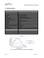
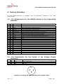
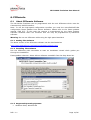
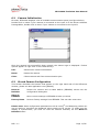
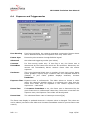
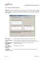
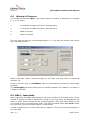
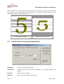
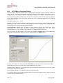
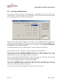
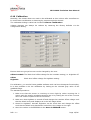
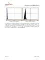
MV-D1024-TrackCam
User Manual
REV: 1.1
PHOTONFOCUS AG
Bahnhofstrasse 10
8853 Lachen
Phone: +4155451000
Fax: +41554510001
www.photonfocus.com
© 2004 PHOTONFOCUS
MV-D1024-TrackCam User Manual
Index
1.
Introduction............................................................................................... 3
1.1
1.2
The MV-D1024-TrackCam.............................................................................. 4
Frame Grabber ............................................................................................ 4
2.
How To Get Started .................................................................................... 5
3.
Technical Data............................................................................................ 6
4.
Camera Interface ....................................................................................... 7
4.1
4.2
Pin Assignments for the MDR26 Socket of the CameraLink Interface.................... 7
Pin Assignments for the Socket of the Voltage Supply Connector......................... 7
5.
Basic Operation and Features..................................................................... 8
5.1
5.2
5.3
5.4
5.5
5.6
Configuration Interfaces................................................................................ 8
Exposure Control ......................................................................................... 8
Global Shutter ............................................................................................. 8
Region of Interest ........................................................................................ 8
LinLog and Skimming Mode ........................................................................... 8
Status Indicator ........................................................................................... 9
6.
PFRemote................................................................................................. 10
6.1
6.1.1
6.1.2
6.1.3
6.2
6.3
6.4
6.4.1
6.5
6.6
6.7
6.8
6.9
6.10
About PFRemote Software ........................................................................... 10
Getting The Software ............................................................................... 10
Installing The Software ............................................................................ 10
Supported Operating Systems ................................................................... 10
Camera Initialization .................................................................................. 11
Stored Camera Configuration ....................................................................... 11
Exposure and Triggermodes ........................................................................ 12
Advanced Triggering Modes ...................................................................... 13
Window Of Interest .................................................................................... 14
MROI / Mask Mode ..................................................................................... 14
Characteristic Curves And Amplification ......................................................... 15
LUT Editor (Look-up Table).......................................................................... 16
LinLog and Skimming ................................................................................. 17
Calibration ............................................................................................. 18
7.
Mechanical Dimensions ............................................................................ 20
8.
Important Notes ...................................................................................... 21
8.1
8.2
8.3
8.4
Storage and Transport ................................................................................ 21
Declaration of Conformity............................................................................ 21
Package Content ........................................................................................ 22
Accessories ............................................................................................... 22
9.
Service Information ................................................................................. 23
9.1 Guarantee Conditions ................................................................................. 23
9.1.1 Guarantee Claims.................................................................................... 23
9.1.2 Repair Time............................................................................................ 23
9.1.3 Claims for Damages................................................................................. 23
9.1.4 In Case of Damage .................................................................................. 23
9.1.5 Safety Hints ........................................................................................... 24
10.
Literature ................................................................................................. 25
11.
Document History .................................................................................... 26
REV: 1.1
Page 2/26
MV-D1024-TrackCam User Manual
1. Introduction
High-speed megapixel CMOS camera for fast tracking applications
The MV-D1024-TrackCam from Photonfocus is aimed at demanding applications in fast
image processing.
The highlight of this camera is the fast configuration interface. This makes it possible to
use a frame-to-frame camera control with up to 40 Mbit/s, instead of the usual 9.6
kbit/s.
The camera provides an exceptionally high dynamic range of up to 120dB at a resolution
of 1024 x 1024 pixels and a frame rate of up to 75 full images per second. It is built
around a CMOS image sensor that has been specially developed by Photonfocus.
The principal advantages of the Photonfocus CMOS technology are:
1. Low power consumption at high speeds
2. Resistance to blooming, smear, and image lags
3. Extremely high image contrast achieved by LinLogTM technology
With the fast configuration interface, in combination with ROI and LinLogTM technology,
Photonfocus offers an absolutely unique product designed for:
•
Tracking of fast moving objects
•
Simultaneous inspection of different regions
•
Shot-to-shot definition of ROI, exposure time and LinLogTM settings
•
The MV-D1024-TrackCam is targeted to
•
Industrial (welding process, welding inspection, PCB inspection)
•
Sport (movement analysis, object tracking)
•
Research and development
The compact size of only 55 x 55 x 46 mm³ makes the MV-D1024-TrackCam the perfect
solution for applications in which space is at a premium.
With the digital camera series, Photonfocus has proven that the image quality of modern
CMOS sensors is now appropriate for a wide range of applications.
Photonfocus is ISO 9001 certified. All products are produced with the latest techniques in
order to ensure the highest degree of quality and to satisfy the requirements of our
customers.
REV: 1.1
Page 3/26
MV-D1024-TrackCam User Manual
1.1
The MV-D1024-TrackCam
The MV-D1024-TrackCam is a high-end CMOS megapixel camera with global shutter. It
has a fast configuration interface that lets you modify the most important camera
configuration parameters at speeds up to 40 MBaud.
The camera includes the following features:
•
CMOS Progressive scan global shutter, monochrome
•
Up to 75 fps full frame rate
•
LinLogTM Pixel with up to 120 dB dynamic range
•
CameraLink© -Interface
•
Internal Lookup Table
•
8 Bit digital resolution
•
Region of interest (ROI)
•
Skimming: Mode in which small signal gain of a pixel is increased
•
Programmable via a high-speed Configuration Interface or an RS-232 serial port
•
Designed for frame grabber microEnableIII-fast configuration by Silicon Software.
•
C-Mount objective mount
1.2
Frame Grabber
The MV-D1024-TrackCam is designed to be used with the microEnableIII-fast
configuration frame grabber from Silicon Software. This special frame grabber version
accesses the MV-D1024-TrackCam via the high-speed configuration interface. The
camera is controlled and programmed with the frame grabber software.
However it can be run with any Photonfocus-compliant frame grabber (see [FGLIST] in
Literature). In this case the camera can be programmed with the tool PFRemote (see
chapter 6), but fast configuration is not possible.
REV: 1.1
Page 4/26
MV-D1024-TrackCam User Manual
2. How To Get Started
1. Remove the camera from its packing and ensure that it is complete and
undamaged. If any damage has occurred during transport, please contact the
transport company and your distributor immediately.
2. Connect the camera to the microEnableIII-fast configuration frame grabber with a
suitable CameraLink© cable.
Important Note: Only cables can be used where each wire-pair is shielded. Thus
the following Phontonfocus cables cannot be used: Part no. 704020.052 and
704020.102.
Warning: Do not connect or disconnect connections while camera power is on.
3. The camera is delivered with a 3-pole power plug. Ensuring that the maximum
operating voltage is not exceeded, connect the camera to a suitable power supply
(+5V DC +/-10%).
4. To use the camera in the Fast Configuration mode, please read the “getting
started” section of the Silicon Software Fast Configuration manual ([ME_FC]).
5. Additional functions can be programmed with the PFRemote tool (see chapter
PFRemote) or with Photonfocus pflib, delivered with PFRemote tool.
REV: 1.1
Page 5/26
MV-D1024-TrackCam User Manual
3. Technical Data
Technical Data for the MV-D1024-TrackCam
Number of pixels
Pixel size
Optically active area
Optical diagonal
Objective mount
Characteristic
Full well capacity
Sensitivity
Noise
Fixed Pattern Noise
Dynamic range in linear mode
Dynamic range in LinLogTM mode
Analog amplification
Spectral range
Optical fill factor
Data interface
Data resolution
Pixel clock
Internal pixel clock
External clock rate CameraLink interface
Maximum frame rate
Shutter type
Exposure time
Configuration interface
High-Speed configuration interface
Voltage supply
Power consumption
Dimensions
Weight
CE Test
1024 x 1024
10.6 µm x 10.6 µm
10.9 mm x 10.9 mm
15.42 mm Î 1” Standard optics
C-mount
Linear or LinLogTM adjustable
200 ke10 µJ/m2/LSB @ 630 nm, 8 bit
< 0.5 Grey level standard deviation @ 8 bit
< 3 Grey level standard deviation @ 8 bit
> 48 dB @ 8 bit
> 120 dB
1 or 4
400 nm – 900 nm (see Fig. 1)
35%
CameraLink
8 bit, or 9 to 8 bit LUT
2x40 MHz
4x20 MHz
10 MHz to 20 MHz
75 fps @ Tint = 10 µs
global shutter
1 µs – 0.5 s in steps of 50 ns
RS232 Standard, 9600 baud, 1 Start bit, 1 Stop bit, no Parity bit
Synchronous transmission < 40MBaud, 1 Start bit, 1 Stop bit, no
Parity bit
+5V DC +/-10%
2W
55 mm (B) x 55 mm (W) x 50 mm (H)
200g
Approved (see chapter 8.2)
Fig. 1: Quantum efficiency as function of wavelength
REV: 1.1
Page 6/26
MV-D1024-TrackCam User Manual
4. Camera Interface
The MV-D1024-TrackCam is equipped with a CameraLink interface in the base
configuration.
4.1
Pin Assignments for the MDR26 Socket of the CameraLink
Interface
PIN I/O
Name
Description
1
2
3
4
5
6
7
8
9
10
11
12
13
14
15
16
17
18
19
20
21
22
23
24
25
26
S
SHIELD
N_XD0
N_XD1
N_XD2
N_XCLK
N_XD3
P_SERTOCAM
N_SERTOFG
N_CC1
P_CC2
N_CC3
P_CC4
SHIELD
SHIELD
P_XD0
P_XD1
P_XD2
P_XCLK
P_XD3
N_SERTOCAM
P_SERTOFG
P_CC1
N_CC2
P_CC3
N_CC4
SHIELD
SHIELD
Shield
Negative LVDS Output, CameraLink Data D0
Negative LVDS Output, CameraLink Data D1
Negative LVDS Output, CameraLink Data D2
Negative LVDS Output, CameraLink Clock
Negative LVDS Output, CameraLink Data D3
Positive LVDS Input, Serial Communication to the camera
Negative LVDS Output, Serial Communication from the camera
Negative LVDS Input, External Trigger signal EXSYNC
Positive LVDS Output, not used
Negative LVDS Input, serial clock (Fast configuration interface)
Positive LVDS Input, data (Fast configuration interface)
Shield
Shield
Positive LVDS Output, CameraLink Data D0
Positive LVDS Output, CameraLink Data D1
Positive LVDS Output, CameraLink Data D2
Positive LVDS Output, CameraLink clock
Positive LVDS Output, CameraLink Data D3
Negative LVDS Input, Serial Communication to the camera
Positive LVDS Output, Serial Communication from the camera
Positive LVDS Input, external Trigger signal EXSYNC
Negative LVDS Input, not used
Positive LVDS Input, serial clock (Fast configuration interface)
Negative LVDS Input, data (Fast configuration interface)
Shield
Shield
PW
O
O
O
O
O
I
O
I
I
I
I
PW
PW
O
O
O
O
O
I
O
I
I
I
I
PW
PW
4.2
Pin Assignments for the Socket of the Voltage Supply
Connector
PIN
I/O
Name
Description
1
2
3
PW
PW
PW
VDD
GND
VDD2
+ 5 V voltage supply
Ground
Reserved
3
1
2
Connector socket Nr. 09-0408-90-03 for the voltage supply
REV: 1.1
Page 7/26
MV-D1024-TrackCam User Manual
5. Basic Operation and Features
Note: The high-speed interface can be accessed by the microEnableIII-fast
configurationframe grabber. In this case not all functions described in this section are
available or are replaced by default values (see [ME_FC]).
5.1
Configuration Interfaces
The MV-D1024-TrackCam can be programmed via a:
•
High-speed interface (up to 40 MBaud) that lets you modify important camera
configuration
parameters
with
the
maximum
frame
rate.
Note: this interface is designed for the microEnableIII-fast configuration frame
grabber.
•
A RS232-interface working at 9600 Baud (included in CameraLink© interface).
5.2
Exposure Control
Note: When using the high-speed interface, exposure is controlled by the microEnableIIIfast configuration frame grabber.
Exposure can be controlled by applying external synchronisation signals (see section
6.4). A free-run mode is also available.
5.3
Global Shutter
The sensor used in the MV-D1024-TrackCam uses a global shutter, i.e. all pixels are
exposed at exactly the same time.
5.4
Region of Interest
With the MV-D1024-TrackCam camera, it is possible to increase the image data rate by
reading out only a part of the pixel matrix. The user can define a region of interest (ROI)
within the sensor to be transmitted to the frame grabber and thus higher frame rates can
be achieved.
5.5
LinLog and Skimming Mode
The LinLogTM CMOS image sensor from Photonfocus employed in the MV-D1024TrackCam allows the user to adapt the characteristics of the sensor to the requirements
of the application.
•
Linear mode: For normal applications that do not require high contrast, the
sensor can be operated in linear mode.
•
Skimming mode: For applications having short exposure times and low
illumination intensity, it is advisable to activate skim mode, in which a non-linear
amplification, similar to a gamma correction, occurs in the pixel so that small
signals are amplified significantly more than large signals.
•
LinLogTM mode: In situations involving high intrascene contrast, compression of
the upper grey level region can be achieved with the LinLogTM Technology. At low
intensities, each pixel shows a linear response. At high intensities, the response
changes to logarithmic compression. The transition region between linear and
logarithmic response can be smoothly adjusted and is continuously differentiable.
Skimming and LinLogTM can be combined to achieve maximum control of the sensor
output. Please refer to application note [AN001] for detailed information on the setting of
LinLogTM.
REV: 1.1
Page 8/26
MV-D1024-TrackCam User Manual
5.6
Status Indicator
A two color LED on the rear of the camera indicate the camera status to the user. In
normal operation the LED lights green when an image is being produced. At low frame
rates a flickering can be observed that changes to a continuous light at high frame rates.
Since the light intensity is dependent on the relation between exposure time and readout time, the light from the LED can practically disappear when using small ROI and long
exposure times.
A red LED indicates that serial communication on the RS232-interface is active.
REV: 1.1
Page 9/26
MV-D1024-TrackCam User Manual
6. PFRemote
6.1
About PFRemote Software
The MV-D1024-TrackCam can be programmed with the tool PFRemote which uses the
CameraLink© RS232-interface.
Note: To use the high-speed configuration interface you need the microEnableIII-fast
configuration frame grabber from Silicon Software. Please refer to the frame grabber
manual ([ME_FC]). In this case the camera is programmed by the frame grabber
software. However there are functions that can only be programmed by PFRemote
software.
Warning: Do not use PFRemote while using the high-speed interface!
6.1.1 Getting The Software
The latest version of the PFRemote software can be downloaded at:
http://www.photonfocus.com/html/eng/support/software.php
6.1.2 Installing The Software
Run the PFRemote_SDK executable to start an installation wizard which guides you
through the installation.
Framegrabber selection: Select Silicon Software menable3 from the drop-down list.
6.1.3 Supported Operating Systems
•
Windows 2000, Windows XP
REV: 1.1
Page 10/26
MV-D1024-TrackCam User Manual
6.2
Camera Initialization
On start, PFRemote displays a list of available communication ports (see figure below).
Double-click on siso0 if your camera is connected to the input A of the Silicon Software
framegrabber, double-click on siso1 if your camera is connected to the input B.
Once the camera has successfully been opened, the camera type is displayed. Further
options appear on right click on the camera entry:
Info
Shows some camera information
Reset
Resets the camera
Close
Closes camera and frees communication port
6.3
Stored Camera Configuration
This section describes the buttons that appear on the right hand side of the PFRemote
window, please see also application note [AN004].
Reset to
Defaults
Resets the camera and re-reads default (EEPROM) values into the
configuration dialog box.
Store in
EEPROM
Store current settings in EEPROM as boot-up values.
Factory Reset
Recover factory settings from EEPROM. This can take some time.
Please note: Some configuration parameters such as LinLogTM and Skimming values can
not be read out, therefore the displayed values might not be correct. To make sure the
display is synchronized, you have to reset the camera manually via the Reset to
Defaults button.
REV: 1.1
Page 11/26
MV-D1024-TrackCam User Manual
6.4
Exposure and Triggermodes
Free Running
Free Running Mode; the camera generates consecutive frames whose
rate is determined by the set exposure time resp. frame time.
Extern Sync
External synchronization through EXSYNC signal.
Advanced
Set advanced triggering modes (see below)
Constant
FrameRate
For free-running mode only: If this flag is set, the frame rate is
determined by the frame time which can be set below. Otherwise, the
camera will immediately deliver another frame after the sensor
exposure.
LinePause
This is the horizontal blank time in number of pixel clock cycles. Some
frame grabbers require larger numbers than the standard default 8
(fastest). If your frame grabber displays artefacts, increase
LinePause.
Exposure Time Exposure time in milliseconds. The slider allows to choose a value
within the camera's possible range in a nonlinear way. Note that the
frame time slider may be adjusted if the chosen exposure time
requires so - read below
Frame Time
If Constant FrameRate is set, the frame rate is determined by the
given frame time in milliseconds. Note that, if this time is less than the
exposure time, the Exposure Time slider will be adjusted.
Frame Rate
The calculated frame rate in frames per second [fps]
The frame rate display is updated whenever a relevant value is changed. This value can
not be edited (use frame rate slider and Constant FrameRate mode for precise frame rate
control).
REV: 1.1
Page 12/26
MV-D1024-TrackCam User Manual
6.4.1 Advanced Triggering Modes
Important: There are restrictions on the LinLogTM functionality with some triggering
modes, except Ext. Trigger with programmed exposure. In all other cases, the COMP
value must be set to 0.0 in order to have LinLogTM work correctly. Other values may
show no effect.
Slave mode
External Master clock synchronization via the MCLK wires.
Sync pulses high
active
This is the default. If deselected, the trigger signals must be
inverted (and the schemes below must be thought inverse as well)
Ext. Trigger with
programmed
exposure
On sync pulse start, the programmed exposure (slider
ExposureTime) begins.
Ext. Trigger
exposure start,
Exp stop
Not available in TrackCam.
Combined
Trigger/Exposure
The length of the ExSync pulse determines the exposure time.
REV: 1.1
Page 13/26
MV-D1024-TrackCam User Manual
6.5
Window Of Interest
The Window Of Interest (WOI) (also called region of interest) is defined as a rectangle
[x, y, w, h] where
x
X coordinate of upper left corner, starting with 0
y
Y coordinate of upper left corner, starting with 0
w
Width of window
h
Height of window
The rows and columns are counted beginning at 0, i.e. the last row and the last column
have the address 1023.
Please note that certain restrictions apply to the start and stop value of horizontal
direction (X):
If this is not the case, the LinePause value is automatically increased to avoid image
artefacts.
The LineHopping attribute defines the line readout stepping. For example, a number of
2 skips all odd lines.
6.6 MROI / Mask Mode
When activated, the MROI mode applies a maximum number of 16 masks to the current
window of interest. A mask is defined as a range of scan lines which are skipped and not
read out which further speeds up the image acquisition. Note that mask windows may
not overlap and are not checked for sanity. The parent window (Main WOI) must include
the first mask, but may exclude trailing, unused masks.
A mask is defined by its Y start value and the height H. These are entered analogous to
the main ROI.
REV: 1.1
Page 14/26
MV-D1024-TrackCam User Manual
As an example, the greyed out areas on the 'zebra 5' denote the mask areas. The read
out result in the frame grabber is displayed on the right (the black lines are just
displayed to better visualize the seams).
Picture with 4 masks
6.7
Resulting 5 image stripes
Characteristic Curves And Amplification
High Gain
Toggle High Gain amplification.
Resolution
Choose camera ADC resolution (bit depth), LUT or LFSR (Random test
pattern).
LUT slot
Switch to LUT number n
Edit LUT
Open LUT editor window (see below)
REV: 1.1
Page 15/26
MV-D1024-TrackCam User Manual
6.8
LUT Editor (Look-up Table)
The LUT editor allows to create look-up tables which digitally re-map intensity values to
other values. The value conversion is directly done on the camera, whereas an input
range [0, n] (n according to camera bit depth) is mapped to a output range of [0, 255].
The LUT editor displays either spline curves or free points (whereas the free point display
is not very accurate, since the input values can cover a greater range than the canvas
display's size in x).
The input range is [0 ... 511].
Editing of the LUT curve happens by dragging the control points in Spline mode or simply
painting on the window in Free mode. Once the curve is ready to be uploaded, you
should first test it in the camera's RAM (Default).
Pressing Send uploads the LUT data to the camera (which can take some time,
depending on the frame grabber dependant implementation of the serial
communication). If LUT mode is not enabled, it is automatically turned on.
The LUT finally can be stored in one of the [m] available EEPROM slots of the camera by
selecting the destination with the chooser right next to the Send button.
Further, LUT tables can be downloaded (Receive) from the camera and stored to disk.
Depending on the curve mode, the curve parameters are either
[Spline mode]: Saved in a LUT spline set by entering the setting name in the LUT spline
sets choice and pressing Save
[Free mode]: Saved in a readable ascii hex code dump file.
If in spline mode, a set simply can be chosen from the drop down choice. Entries can be
erased with the Delete button.
REV: 1.1
Page 16/26
MV-D1024-TrackCam User Manual
6.9
LinLog and Skimming
The LinLogTM feature provides a semi-logarithmic, adjustable behaviour of the camera
characteristics, so that extreme white intensities can be monitored without saturation
while keeping optimum resolution on dark areas.
Note that the LinLog state might not be known to the application after opening the
camera configuration dialog. Therefore, the LinLog Control choice displays "Default". Use
this choice to turn LinLog off or explicitely on, or reset the camera (Reset to Defaults)
to update the current default settings.
The Skimming slider is only accessible after a explicit update of the settings.
Quick steps for LinLog™ adjustment (refer to application note [AN001]):
Choose LinLog Control: LinLog2. Default stands for the default setting which is only
well defined if the camera is reset, since LinLog values can not be read back. The LinLog
setting makes only use of the LL1 parameter; see below.
Set the LinLog high compression LL1 to a value such that your maximum intensity spot
in the image resolves well or just starts to show bright gray.
Set the low compression LL2 to a value less than LL1.
Fine tune the COMP fraction value around small values in the range of [0, 100] to
achieve an image with optimum dynamical resolution in high intensity ranges. This may
require some iteration through the settings.
The Skimming mode allows to brighten up darker areas (non-linear).
REV: 1.1
Page 17/26
MV-D1024-TrackCam User Manual
6.10 Calibration
Normally, the camera does not need to be calibrated as this is done after manufacture.
In some cases recalibration or detuning by purpose might be desired.
The calibration dialog is called via the Menu Camera->Calibration.
Voltage changes can always be undone by restoring the factory defaults via the
configuration dialog.
Entries which are greyed out can not be changed by the user.
Offset LowGain The black level offset voltage for the LowGain setting (i.e. HighGain off
Offset
HighGain
Black level offset voltage for HighGain setting
For calibration, you need a frame grabber software with real time histogram functionality.
It is also possible to do the calibration by looking at the minimal gray value of the
grabbed image.
The standard procedure:
1. Make sure that the sensor is receiving no more light by either covering the C
mount with the usually included protection cap or by closing the iris of the C mount
lens. Set camera exposure time to minimum.
2. Make sure that HighGain is turned off and change the LowGain offset voltage such
that the black level peak displays as in the left image below.
3. Same for HighGain: Activate HighGain via the check box and change the offset
such that the black level distribution looks like in the image on the right.
4. Store the values in the EEPROM via the Store in EEPROM button.
REV: 1.1
Page 18/26
MV-D1024-TrackCam User Manual
LowGain mode histogram
HighGain mode histogram
The Skimming is normally changed in the LinLog panel but can be changed here as well,
if the camera is run in skimming mode by default. In this case, the offset voltage may
need to be adjusted. Note that the skimming effect is reverse to the voltage, i.e. higher
voltage means: less skimming. Note that with too low skimming voltage settings, the
image may no longer look good. Handle with care.
REV: 1.1
Page 19/26
MV-D1024-TrackCam User Manual
7. Mechanical Dimensions
REV: 1.1
Page 20/26
MV-D1024-TrackCam User Manual
8. Important Notes
Photonfocus reserves the right to make changes to its products without notice.
Photonfocus products are neither intended nor certified for use in life support systems or
in other critical systems. The use of Photonfocus products in such applications is
forbidden. Photonfocus, LinLog, LinLog2 and CameraLink are registered trademarks in
Switzerland and in other countries.
8.1
Storage and Transport
During storage and transport, the camera should be protected against vibration, shock,
moisture and dust. The original packing protects the camera adequately from vibration
and shock during storage and transport. Please either retain this packing for possible
later use or dispose of it according to local regulations.
8.2
Declaration of Conformity
We, the manufacturer
Photonfocus AG,
Bahnhofplatz 10
CH 8853 Lachen
Switzerland Europe
hereby declare that the products of the camera MV-D1024-TrackCam, released in 2004,
conforms to the following standards or other normative documents:
•
EN61000-6-2
•
(2001)
•
EN61000-6-3
•
(2001)
•
EN61000-4-2
•
(1995)
•
EN61000-4-3
•
(1996)
•
EN61000-4-4
•
(1995)
•
EN61000-4-6
•
(1996)
•
EN55022
•
(1994)
This declaration becomes void in case of any changes on the product without written
authorization by Photonfocus.
REV: 1.1
Page 21/26
MV-D1024-TrackCam User Manual
8.3
Package Content
The package includes the following:
•
Camera
•
Lens protective cap
•
enclosing note
•
Power supply connector
Photonfocus reserves itself the right to change the content at any time without indication
of reasons.
8.4
Accessories
For the camera MV-D1024-TrackCam are several accessories available. For detailed
information about the listed parts refer to the Photonfocus Web page
www.photonfocus.com.
•
CLB 26 Digipeater – CameraLink Repeater for extended cable length
•
CameraLink cables
•
Power supply
REV: 1.1
Page 22/26
MV-D1024-TrackCam User Manual
9. Service Information
For product enquiries and quotations, please contact one of our distributors in your area.
A list of distributors can be found on our web-site:
www.photonfocus.com
Product information, documentation and software updates can also be found on our website.
9.1
Guarantee Conditions
9.1.1 Guarantee Claims
The manufacturer alone reserves the right to recognize guarantee claims. The guarantee
will be rendered null and void in the event of unauthorized manipulation, mechanical
damage or damage arising from inappropriate use or from mechanical or electrical
modifications, especially soldering. The guarantee will also be invalidated if the apparatus
is used for purposes for which it was not designed, if it is incorrectly connected or if it is
not used according to the operating instructions.
Guarantee work can only be assured and carried out by the manufacturer.
9.1.2 Repair Time
Repair time will normally be a maximum of 10 working days for repairs to a device for
which a legitimate guarantee claim is made.
9.1.3 Claims for Damages
Claims for damages of all kinds, especially those arising from use, are excluded. Liability
is limited, in all cases, to the value of our product.
9.1.4 In Case of Damage
If the equipment is defective, return it, in the original packing and with a copy of the
receipt, to the following address:
Photonfocus AG
Bahnhofplatz 10
CH-8853 Lachen
Important: Include a written description of the fault as well as your full postal address.
The equipment will be forwarded in your name to the service department and, in the
event of a legitimate guarantee claim, returned to you without freight charges.
REV: 1.1
Page 23/26
MV-D1024-TrackCam User Manual
9.1.5 Safety Hints
The apparatus conforms with approved electro-magnetic standards. Opening the
apparatus is not permitted. Furthermore, all guarantee claims will be invalidated by
inappropriate use. In all circumstances, the following should be noted:
•
The apparatus may only be used for the purpose described.
•
The apparatus is only suitable for indoor use. Protect it from moisture and heat.
•
The permitted operating temperature range is 0°C to 60°C.
•
Never attempt repairs yourself. Repairs may only be carried out by trained expert
staff.
•
Moreover, every piece of equipment is tested before delivery and has a guarantee
symbol attached.
•
For cleaning purpose, use only a dry soft cloth. Never use water or chemicals.
REV: 1.1
Page 24/26
MV-D1024-TrackCam User Manual
10.
Literature
[AN001]
Application note AN001 “LinLog 2” found on
http://www.photonfocus.com/html/eng/support/applicationNotes.php
[AN004]
Application note AN004 “Reset Strategies” found on
http://www.photonfocus.com/html/eng/support/applicationNotes.php
[FGLIST]
Frame grabber compatibility list
http://www.photonfocus.com/html/eng/support/framegrabbers.php
[ME_FC]
REV: 1.1
User Manual for microEnableIII-fast configuration frame grabber, Silicon
Software ( http://www.siliconsoftware.de)
Page 25/26
MV-D1024-TrackCam User Manual
11. Document History
Document revisions
REV
Changes
Date
1.0
1.1
First revision
Added note that mode “ext. trigger, exposure start, Exp stop” is not available.
Slight modifications in Getting started chapter
2004-05-17
2004-07-07
REV: 1.1
Page 26/26
![GammaWare[Gw] User's Guide](http://vs1.manualzilla.com/store/data/006910084_1-8196ffa7e35032d3615309d6abf1f30d-150x150.png)