1
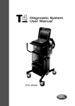
Land Rover
User Manual
This manual will aid you in the correct maintenance
and usage of your TestBook, from unpacking and
getting started, to assisting during Fault Diagnosis.
It is recommended that you use this manual in
conjunction with your TestBook unit.
This book contains the following sections:
Introduction
Hardware
Diagnostics
Help Desk
Publication Part No. LRL 0365ENG
2000 Land Rover
INTRODUCTION
CONTENTS
Page
INTRODUCTION ...................................................................................................... 1
INTRODUCTION
INTRODUCTION
Land Rover’s TestBook programme has successfully
applied modern Information Technology to the
servicing and repair of its vehicles.
TestBook is a portable computer designed to help a
service technician diagnose electrical systems,
engine systems, and transmission systems in Land
Rover vehicles.
TestBook can draw current from a 12 volt vehicle
battery or from an AC/DC power supply. It prompts
the service technician to enter commands for
selecting self tests, retrieving diagnostic information,
or running vehicle diagnostics.
TestBook has already made a major contribution to
raising standards of customer satisfaction and
promoting the business success of dealerships and
their staff.
As with any progressive activity, TestBook benefits
from continuous improvement to all its support
facilities, based on the real -life experience that we
have all gained so far.
So this Technician’s Handbook has been designed
to consolidate all the information and guidance that
used to exist in a variety of publications, within this
single easy-reference book. Virtually everything that
you need to know is in this handbook - including
details of what to do if you can’t find the answer you
need !
Although much of the information given here is
similar to that previously published, many items
have been updated, extra information has been
added and efforts have been made to clarify certain
parts of the text.
Land Rover is constantly seeking ways to improve
the specification and design of its vehicles and
alterations take place continually.
Whilst every effort is made to produce upto date
literature, this User Manual should not be regarded
as an infallible guide to current specification, nor
does it constitute an offer for the fitment of any
particular system or component.
For example, it was felt that the number of separate
publications that technicians might need to refer to
when using TestBook had become excessive, and
difficult to manage in a workshop situation.
1
HARDWARE
CONTENTS
Page
TESTBOOK INSTALLATION GUIDE ....................................................................... 1
FURTHER DETAILS OF TESTBOOK EQUIPMENT ................................................ 3
PHYSICAL SPECIFICATIONS ................................................................................. 8
ENVIRONMENTAL SPECIFICATIONS .................................................................... 8
PREPARING A SITE FOR TESTBOOK ................................................................... 9
TROLLEY INSTALLATION GUIDE (TESTBOOK 1) ................................................. 9
TROLLEY INSTALLATION GUIDE (TESTBOOK 2) ............................................... 11
CLEANING TESTBOOK (TESTBOOK 1) ............................................................... 15
CLEANING TESTBOOK (TESTBOOK 2) ............................................................... 15
POWERING TESTBOOK (TESTBOOK 2) .............................................................. 16
POWERING TESTBOOK (TESTBOOK 1) .............................................................. 16
INTERNAL POWER (TESTBOOK 2) ...................................................................... 17
INTERNAL POWER (TESTBOOK 1) ...................................................................... 18
ROAD TEST POWER SUPPLY .............................................................................. 18
USING THE TOUCH SCREEN ............................................................................... 19
ADJUSTING THE DISPLAY ................................................................................... 20
TURNING TESTBOOK "OFF" ................................................................................ 21
BATTERY CHECKING AND REPLACEMENT ....................................................... 22
BATTERY RESTORATION PROCEDURE (TESTBOOK 2) ................................... 22
BATTERY RESTORATION PROCEDURE (TESTBOOK 1) ................................... 23
BATTERY REPLACEMENT PROCEDURE (TESTBOOK 1) .................................. 23
FUSE REPLACEMENT (TESTBOOK 2) ................................................................ 24
FUSE REPLACEMENT (TESTBOOK 1) ................................................................ 25
TESTBOOK FAN FILTER (TESTBOOK 1) ............................................................. 25
TESTBOOK FAN FILTER (TESTBOOK 2) ............................................................. 26
USING COMPACT DISCS (CDs) (TESTBOOK 2) ................................................. 27
USING COMPACT DISCS (CDs) (TESTBOOK 1) ................................................. 29
LOADING A CADDY INTO TESTBOOK 1 .............................................................. 30
CD CLEANING PROCEDURE ............................................................................... 30
BEGINNING WORK WITH TESTBOOK ................................................................. 31
CONFIGURATION .................................................................................................. 34
HOW TO INSTALL TESTBOOK SOFTWARE ........................................................ 37
SCREEN FORMAT ................................................................................................. 38
HOW TO VIEW PICTURES .................................................................................... 39
THE RETURN DESTINATION MENU .................................................................... 41
INTEGRITY TESTS ................................................................................................ 42
ROVING PROBE TEST .......................................................................................... 44
SERVICING TESTBOOK ........................................................................................ 46
HARDWARE
TESTBOOK INSTALLATION GUIDE
Unpacking Your TestBook equipment
NOTE: This is for general information your contents inspection should only be
against the checklist included with your
equipment.
Remember, before unpacking and using your
TestBook, that you are dealing with a complex and
expensive piece of electronic equipment. Although it
has been designed to be reasonably robust for
workshop use, it still needs to be handled with rather
more care than most other workshop equipment.
Look after your TestBook, and it will look after you !
Remove the equipment carefully from its packaging,
setting it out in a clean, dry area such as a clear
bench or table, so that you can check the individual
items off the checklist supplied with each TestBook.
If any items are missing, please contact your Help
Desk.
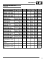
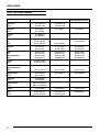
Full TestBook Packages (e.g.UK market)
Land Rover only
TestBook
x
Trolley
x
Printer
x
Land Rover Cables
x
Old * Land Rover
Cables
x
Pressure/Vacuum kit
x
EGR Break-out Box
x
Transfer Break-out
Box
x
Cable Cabinets
x
L R Cable Cases
x
* "Old" in this context means cables to suit those models that do not have a J1962 diagnostic connector.
1
HARDWARE
Basic TestBook Packages (e.g. some export
markets)
Basic Land Rover
TestBook
x
Land Rover Cables
x
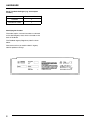
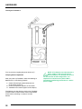
Identifying the Product
The model, option, and serial numbers are located
on the Serial/Agency label, which is located on the
back of TestBook.
The TestBook Agency/Regulatory label is shown
below.
Please ensure that you read the Serial / Agency
label for product warnings.
2
HARDWARE
FURTHER DETAILS OF TESTBOOK EQUIPMENT
This explains the contents of some of the items
listed on the tables on the previous page.
NOTE: Again, the following is for general
information, and is NOT a substitute for
the checklist included with your TestBook
"package".
TestBook
For "Full Packages", this means a TestBook unit and a road test
power supply.
However, for "Basic Packages", this also includes a mains supply
power unit, (which on "Full Packages" is included with the Trolley).
Trolley
The mobile stand that holds the TestBook at a comfortable working
height, and makes it easy to position it alongside vehicles in the
workshop. It is fitted with the mains power supply transformer unit,
printer power supply transformer unit and also provides a convenient
mounting for the Printer and CD storage.
Printer
Printer.
Land Rover Cables
These include: Roving probe, 20ft (6.1m); Port 1 loopback cable;
VCSI (Vehicle Communication Serial Interface) cable; 500A current
clamp/transducer; VCSI extension cable;
Transducer extension cable.
J1962#2 (blue) cable
J1962#3 (green) cable
J1962#5 (grey) cable
J1962#4 (black) cable;
4x4 J1962 Airbag adaptor Probe Kit
NOTE: "#" or "hash" is an American symbol for "number".
Old Land Rover Cables
14 CUX adaptor;
ABS adaptor;
Air Suspension adaptor;
Airbag Adaptor.
3
HARDWARE
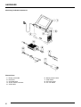
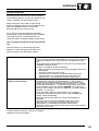
Identifying TestBook Components
External Parts
1.
2.
3.
4.
5.
4
Display and Cable
Base Unit
CD-ROM Drive
AC/DC Power Converter
VOM Cable
6.
7.
8.
9.
Battery Power Cable
VCSI Cable
AC Power Cord
On / Off Switch
HARDWARE
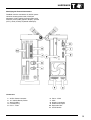
Identifying the External Connectors
TestBook contains connectors for AC/DC power
converter, battery power cable, VOM (volt
ohmmeter), VCSI (vehicle communication serial
interface), VGA (video graphics adapter), parallel
(LPT1), serial (COM1), keyboard and display.
Connectors
1.
2.
3.
4.
5.
AC/DC Power Converter
12v Vehicle Battery Power
Serial (COM1)
Parallel (LPT1)
Port 1 - VCSI
6.
7.
8.
9.
10.
11.
Port 2 - VOM
VGA
Display Connectors
Audio Level Output
Expansion Slot
On/Off Switch
5
HARDWARE
TestBook display is a monochrome LCD panel with
the following specifications:
TestBook Specifications
The TestBook motherboard contains a PC-AT
compatible board. The main system processor for
TestBook is a 486 DX/2 - 50 MHz microprocessor
with 20MB of system RAM. The internal hard disk
supports the operating system, applications and
data. The CD-ROM allows the dealership technician
to upgrade the software. A separate, light weight
display module with integrated touch screen makes
TestBook easy to use.
• VGA compatible resolution of 640 x 480
• Display modes including graphic as well as text
modes
• Display contrast control via the keypad
• Up to 64 shades of grey TestBook includes a
touch screen input device with a resistive touch
system. TestBook includes an audio speaker
which is controlled by software.
There is an external AC to DC power supply, and an
internal DC to DC power converter system.
TestBook contains an internal rechargeable battery
which eases the transition from the trolley to the
road test power supply.
TestBook includes a Power On Self Test PASSED
indicator LED light and a Battery/External Power
indicator LED. The Power On LED is a single colour,
green. The external/battery LED is single colour,
yellow.
Interface
Volts Ohm Measurement Capabilities
TestBook user interface consists of a display, touch
screen, audio transducer and membrane keypad for
contrast control and two LED indicators for power
and self-test.
The roving probe connects to TestBook via a high
cycle-life Burndy connector. The vehicle connection
is made with two probes. All functions are measured
with these probes. All mode switching takes place
internally. The Roving probe contains an ID resistor
to allow for hardware verification of the proper cable
connection.
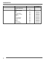
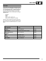
TestBook is configurable to either 50 or 60 Hz. The
ranges of accuracy for TestBook are listed in the
table below:
VOM Specification
Function
Accuracy
DC volts (+ and -)
400 m volts - 4
volts - 40 volts
1% of full scale
AC volts - RMS
400 m volts - 4
volts - 40 volts
1% of full scale
Resistance
800 ohms
1% of reading or 2 ohms whichever is greater
Resistance
80 ohms
+ or - 0.2 ohms
1 amp
1% of full scale
Current
6
Range
HARDWARE
Vehicle Communication Serial Interface (VCSI)
The vehicle communication serial interface (VCSI)
allows TestBook to communicate with specified
electronic control units (ECUs) and other devices
that follow the ISO9141 standard. This international
standard specifies the requirements for setting up
the interchange of digital information between
on-board ECUs of road vehicles and diagnostic
testers.
The ISO 9141 support consists of three main
functional blocks: the asynchronous serial
receiver/transmitter, counter/timers and the ISO
9141 physical interface. The asynchronous serial
receiver/transmitter and counter/timer logic are
implemented using a field programmable gate array
(FPGA). The physical interface is electrically isolated
from TestBook. TestBook VCSI can achieve a baud
rate synchronization from 10 to 10K baud.
TestBook is capable of operating, while not
connected to a vehicle, for no more than 15 minutes
based on a fully charged new battery. The system
clock and configuration RAM on the system board in
TestBook is battery backed up with a NiCAD
(nickel-cadmium) battery.
Mechanical Design
TestBook is composed of two separate enclosures,
a display unit and a base unit. The display unit
houses the display, speaker and touch screen. The
base unit houses all other electronics. The display
unit is attached to the base unit through a pivot
mechanism which allows it to be angled for normal
use, folded down for transporting or removed for
remote usage. The display unit is tethered to the
base unit with one thin cable, allowing it to be easily
moved around the vehicle.
Base Unit Enclosure
Power Sources
TestBook can be connected directly across the
vehicle battery terminals. In this mode of operation
the VCSI and VOM isolations will keep the vehicle
battery ground isolated from the signal ground. The
isolated DC to DC converter will provide the ground
isolation for the peripheral connectors such as the
parallel and serial ports. The peripheral signals are
not isolated. TestBook can also be powered from an
external AC to DC power supply. This mode is
especially useful to recharge TestBook internal
battery while not in use.
When connected to the vehicle TestBook uses DC
power from the vehicle, with a voltage range of 9.7 V
DC to 16V DC. If the vehicle power is lost or
TestBook is disconnected from the vehicle,
TestBook operates from its internal battery pack.
The base unit enclosure consists of sheet metal
parts that form a protective environment for the main
electronics. The enclosure has rubber bumpers at
strategic points to absorb shock from accidental
drops. There is a handle at the top of the unit for
transporting it. The display module has a storage
location on the base unit. The display can be stored
with the LCD facing the base unit. This configuration
will protect the LCD during transportation. The
display module can also be placed so the LCD faces
away from the base unit to allow the user to interface
with the tester without hand holding the display.
Cables and Adapters
The TestBook package contains the road test power
supply. This cable has been designed to operate in
the harsh automotive garage environment. The road
test power supply connects TestBook to the vehicle
battery. This cable is 4.2 metres long. It has red and
black battery clamps at one end and a sub-miniature
D power connector at the other. A black PVC
molded fuse box is located near the clamp end.
7
HARDWARE
PHYSICAL SPECIFICATIONS
Dimensions
Base Unit:
Height
Width
Length
109 mm (4.30 in)
318 mm (12.5 in)
333 mm (13.1212.6 in)
Display Unit:
Height
Width
Length
27 mm (1.06 in)
279 mm (10.98 in)
264 mm (10.39 in)
Connectors
An Input/Output connector area is provided at the
front and rear of TestBook. All connectors follow
industry standards.
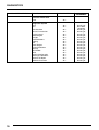
ENVIRONMENTAL SPECIFICATIONS
Conditions
Specifications
Temperature
Operating:
Non-operating:
0° to 40°C (32° to 104°F)
-40° to 70°C (-40° to 158°F)
Humidity
Operating:
Non-operating:
15% to 95% RH at 40°C (non-condensing)
90% RH at 65°C (non-condensing)
Vibration
Operating:
Non-operating:
0.30 G RMS, 5 to 500 Hz
2.41 G RMS, 5 to 500 Hz
Drop
Non-operating
Drop of 36" may cause superficial damage
Shock
Operating:
Transportation:
ESD
Operating:
Survival:
Electromagnetic
Susceptibility
Conducted:
Radiated:
Magnetic:
AC Line Transients
DC Input
8
Low Energy
Pulse:
High Energy
Pulse:
Line Surge:
Line Sag:
Line Drop-out:
velocity change of 350cm/s, half-sine wave form, duration - 3
ms
trapezoidal wave form velocity change of 742 cm/s. Minimum
acceleration, 30g
0 - 15KV Air discharge excluding connectors ± 4KV contrast
discharge excluding connectors
15 - 25KV Air discharge excluding connectors
3 V over frequency range of 30 Hz to 50 Hz 1 V over
frequency range of 50kHz to 400 MHz
10 V/m over frequency range of 14kHz to 1 GHz
1 gauss over frequency range of 47.5 Hz to 198 Hz
3 KV/100kHz Ring Wave
1 KV at 1.2 ms. rise by 50 ms. decay to half peak
+25% for 500 ms
+25% for 500 ms
0V for 10 ms
Reverse Bias
HARDWARE
PREPARING A SITE FOR TESTBOOK
TROLLEY INSTALLATION GUIDE (TESTBOOK 1)
(If you have a TestBook trolley, go on to the next
section).
If you are using a TestBook Trolley, this gives a
convenient, purpose-designed location for your
TestBook.
If you are not using a TestBook Trolley, then you
need to meet the following requirements in siting the
TestBook for use :
The surface must be firm, flat and reasonably level (this is particularly important for satisfactory
operation of the CD disc drive), and any risks of
TestBook falling or being knocked over should
obviously be avoided.
The Trolley is delivered to you as a virtually
complete assembly - you only need to fit the Cable
management bar, the TestBook and its printer, two
additional CD caddy holders plus the mains cord
and you will be ready to begin using TestBook.
The TestBook mains power supply transformer unit
also needs to be securely positioned near to the
TestBook and the power cables protected from
workshop traffic, to prevent accidental disconnection
or damage.
Position TestBook so that you have convenient
access to the cable ports (and with sufficient room to
avoid sharp bends on the connecting cables), as
well as to the touch screen and the CD disc drive.
Take the power lead from the separate mains power
transformer unit and plug it into the power input port
on TestBook, marked by the symbol:
You can then plug the transformer feed cable into
the mains socket to start using TestBook.
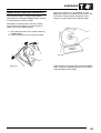
Start by fitting the Cable Management Bar. Unwrap
the two fixing screws in the plastic bag attached to
the trolley handle. Hold the bar so that the cable
notches are uppermost, behind the trolley, and slide
the free ends into the grooves beneath the TestBook
platform. Holding the bar in position, line up the
screw holes in the free ends of the bar with the holes
in the trolley body, insert and tighten the fixing
screws.
9
HARDWARE
Now look at the back of the trolley and locate the
power leads hanging out of the two power
transformer units. Plug the right hand lead into the
power port at the right rear of the TestBook. The
identifying symbol above this port is as shown in the
previous section.
Next,carefully lower the TestBook onto the trolley
platform so it fits securely within the locating rim and
so that the name "TestBook" shows right way up at
the front of the trolley. Find the two Torx screws and
two plastic wire clips from the small parts bag then
plug the AC mains feed cable into the socket on the
side of the trolley (but do not plug the other end into
a power socket yet). Lead the cable down the the
side of the trolley, securing it it with the cable clips
which should be attached with the Torx screws to
the two pre-threaded holes.These clips protect the
feed plug and socket from strain or disengagement if
the cable should be snagged or pulled.
The next stage is to install the portable DeskJet
printer into the trolley. Place the printer into the
cradle on the trolley. Note that the power and printer
interface sockets are positioned on the same side of
the trolley as the mains feed cable and switch (i.e.
on the right as viewed from the back of the trolley).
Connect the printer power cable (small connector)
and printer interface cable. Note that the power
connector should be rotated slightly on insertion to
ensure that it goes fully home, and butts firmly
against the printer case.
10
HARDWARE
Load paper into the printer. The paper feeder on
your TestBook printer is designed to handle a stack
of dry paper no more than 5mm high. If too much
paper is put in, or if the paper is damp, the feeder
may jam.
Paper should therefore be stored in a warm, dry
place, such as an office, rather than in the
workshop.
Any paper left in the feeder tray at the end of a
working shift should be removed and put back into
store until needed again. If left out overnight it will
absorb moisture from the air as the temperature
falls.
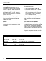
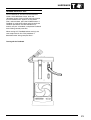
TROLLEY INSTALLATION GUIDE (TESTBOOK 2)
If you are using a TestBook Trolley, this gives a
convenient, purpose-designed location for your
TestBook.
The Trolley is delivered to you as a virtually
complete assembly - you only need to fit the
TestBook, its printer, the trolley door and you will be
ready to begin using TestBook.
Attach the two additional CD caddy holders - these
will be found in the small box at the bottom of the
trolley box.
They snap into place below the two pre-installed
caddy holders - line up the plastic tabs into the
grooves and push each caddy holder firmly into
place. The holders should then be flush to one
another in two rows of two.
You should now have a fully operational TestBook
trolley unit that only requires the mains cord to be
plugged into a mains supply socket in order to start
work. Please note, however, that the internal battery
(discussed in a later section) is supplied in a
discharged state. To fully charge it, you should leave
TestBook plugged into the mains, (but with
TestBook itself turned off) overnight before starting
to use it.
11
HARDWARE
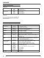
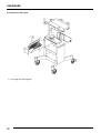
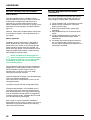
Installing The Trolley Door
1. Put hinge into securing hole.
12
HARDWARE
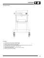
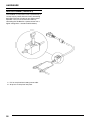
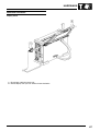
Installing the Printer
Installation
1.
2.
3.
4.
5.
6.
7.
8.
Remove printer door from the TestBook trolley.
Remove the screw and bracket from the trolley.
Remove the printer from the cardboard box.
Place the printer into the trolley, connecting the power lead and centronics cable first.
Locate the printer into the holes in the printer shelf.
Refit the screw and bracket.
Open the printer paper feed, and insert the printer cartridge.
Refit the printer door to the trolley.
13
HARDWARE
IMPORTANT: PROTECTING YOUR TESTBOOK
Whether using a Trolley or other location for your
TestBook, you need to protect it from the following
common workshop hazards:
• Avoid extremes of temperature - the safe
operating range is 0° - 40° Centigrade/Celsius,
and there should always be adequate ventilation
around the TestBook - do not operate it within
any kind of enclosing container. Do not leave
TestBook inside a vehicle in a hot environment
e.g. parked in the sun. When TestBook is out of
use or in storage, the acceptable temperature
range is from - 10° to 60° Centigrade/Celsius.
• TestBook is not proof against water or other fluid
spillages - keep it dry and clean.
• Avoid exposing TestBook to direct sunlight, as
this may fade the screen display.
• Powerful magnetic fields are bad for any
computer - keep TestBook well away from any
heavy electrical workshop equipment, such as
large electric motors, generators, electrical
welding equipment etc.
• Don’t let dust from grinding or resurfacing
equipment get on or into the TestBook.
• Keep TestBook away from sources of chemical
contamination such as paint booths or
degreasing plant, and avoid conditions of
excessive moisture.
• As the screen is made of conventional (not
toughened) glass, avoid any kind of impact. If it
should ever be accidentally broken, beware of
glass shards.
14
HARDWARE
CLEANING TESTBOOK (TESTBOOK 1)
CLEANING TESTBOOK (TESTBOOK 2)
It is important to clean the touch screen periodically
to maintain proper operation. This is best done when
TestBook is turned off - but if you need to remove
contamination while the TestBook is in use, first
touch the upper left corner of the screen, next to the
screen number. You will then see a message "The
display may be wiped now" - and it will be possible
to wipe the screen without all the buttons trying to
respond at once !
Before you clean TestBook, follow these steps:
For the screen glass and other outer surfaces of
TestBook, use a mild, non-abrasive liquid cleaner.
Never spray or pour any type of cleaner directly onto
any part of TestBook - instead, use a soft cloth to
apply a small amount of cleaner. For particularly
tough stains, use a small amount of glass cleaner on
a soft cloth.
1. Shut off the power to TestBook by toggling the
power button to "0" and unplugging the power
cord from its power source and the TestBook.
2. Inspect TestBook cables, connectors and
power cord for any damage or corrosion. If
damaged, replace them immediately.
3. Inspect the display window, cable assemblies
and connectors for any contaminants.
CAUTION: Do not use chlorinated solvents
to clean TestBook.
NOTE: Although TestBook is moisture
resistant, it is not moisture proof. Dry
TestBook off thoroughly after cleaning it.
Cleaning the Base Unit
Wipe the top and bottom covers clean using a soft
cloth and mild detergent or hand soap. Avoid using
petroleum based solvents such as acetone, benzene
or tricloroethylene. They contain chemicals that can
etch plastic surfaces.
Cleaning the Display Window
The display window collects grime during normal
use. Touch the top left hand corner of the touch
screen to "freeze" the screen. Wipe the screen with
a clean, soft, static free cloth. Use a non-abrasive
plastic cleaner and a soft cloth to wipe the display
area. Place a small amount of plastic cleaner on a
soft cloth and wipe clean. Again, avoid using
petroleum based solvents such as acetone, benzene
or tricloroethylene. They contain chemicals that can
etch plastic surfaces.
15
HARDWARE
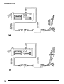
POWERING TESTBOOK (TESTBOOK 2)
POWERING TESTBOOK (TESTBOOK 1)
TestBook normally gets power from its own power
supply transformer when it is plugged into a mains
power supply. This is called "EXTERNAL POWER",
because the power is being supplied from outside
TestBook. It also has an internal battery that
prevents the unit from shutting off for short periods
of time when you need to disconnect it from external
power.
TestBook normally gets power from its own power
supply transformer when it is plugged into a power
point. This is called "EXTERNAL POWER", because
the power is being supplied from outside TestBook.
It also has an internal battery that prevents the unit
from shutting off for short periods of time when you
need to disconnect it from external power.
To turn TestBook ON, first plug the TestBook power
supply into a mains power point. TestBook must be
connected to a power point before it can be turned
ON, as its design prevents it from being turned ON
while it is unplugged.
Press the "ON/OFF" button on the front panel,
located just beneath the display. When turned ON,
the green light on the front panel, next to the power
plug symbol, will light up.
1.
2.
3.
4.
Contrast knob
Green indicator - external power
Amber indicator - internal power
ON/OFF button
IMPORTANT:To turn testbook off, first return to the
welcome screen. At the welcome screen, touch the
"Shutdown" button. Wait until the message "please
turn off TestBook now" appears on the screen.
Then, and not before, press the ON/OFF button. If
TestBook is switched off without going through this
shutdown procedure, the software files on its
memory may be "scrambled", and prevent TestBook
from working correctly next time.
When turning OFF TestBook before moving it, be
sure to eject the CD and its caddy (holder) first. This
procedure is described under "Using Compact
Discs".
16
HARDWARE
INTERNAL POWER (TESTBOOK 2)
To provide brief "stopgap" power while unplugged,
TestBook has an internal nicad battery. It will
provide fifteen minutes of use on a full charge. It is
only meant to provide power when moving TestBook
into and out of a vehicle before and after a road test.
During the road test itself, you must use the Road
Test Power Supply - which is described on the
following page.
Interpreting the Indicator Lights
The indicator lights located on the side panel show
that TestBook is operating as designed. The green
light specifies whether TestBook passed the Power
On Self Test (POST), a diagnostic test that
evaluates system hardware. The yellow light
indicates that TestBook is connected to a power
source other than the internal battery.
17
HARDWARE
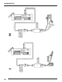
INTERNAL POWER (TESTBOOK 1)
ROAD TEST POWER SUPPLY
To provide brief "stopgap" power while unplugged,
TestBook has an internal nicad battery. The internal
battery is located behind the dummy panel at the
front of TestBook. It will provide between five to ten
minutes of use on a full charge. It is only meant to
provide power when moving TestBook into and out
of a vehicle before and after a road test. During the
road test itself, you must use the Road Test Power
Supply - which is described in the next section.
One of the major advantages of TestBook is that it
can be taken out in a vehicle to carry out diagnostic
work during a road test. To do this, you must use the
Road Test Power Supply. Carry out the following
steps when using the Road Test Power Supply. You
do not need to turn TestBook OFF.
When using battery power, the light on the front of
TestBook will change from the green one adjacent to
the plug symbol to the amber one next to the battery
symbol. This amber light will begin to flash when the
battery power becomes low. This means that the
unit will shut off after a short period of time if you do
not plug it back into an external power supply.
NOTE: The internal nicad battery
recharges whenever TestBook is plugged
into an external power supply - even when
Testbook is not switched on.
NOTE: As with any nicad battery, when the
TestBook internal battery becomes
drained, a period of at least two hours
must be allowed for it to recharge. If you have
removed the power supply with TestBook
operating and the amber light has started
flashing, this indicates that the nicad battery is
nearly drained. If TestBook is connected to a
power supply for only a short period of time after
the amber light has been allowed to flash, the
battery will not have recharged sufficiently to
power TestBook for the normal 5 to 10 minute
18
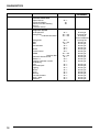
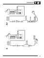
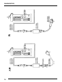
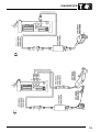
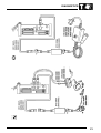
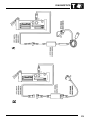
1. Connect the Road Test power Supply to the
battery of the vehicle to be road tested.
Connect the red cable to the battery "+" post.
Always double check that you have connected
the red cable to the correct, positive terminal
before going on to connect the black cable to
the battery "-" post. This is very important, as
the polarity must NOT be reversed.
2. Switch off TestBook’s power supply at the
power point on the side of the trolley.
3. Unplug the power supply from TestBook.
4. Plug the other end of the Road Test Power
supply into TestBook’s power port.
5. Return TestBook to a mains power point as
soon as you finish the road test.
6. When transferring TestBook to and from the
Road Test Supply, remember the limited time
available on the internal battery - don’t let
anything else distract you while doing this !
7. Allow at least two hours to fully recharge the
internal nicad battery. The battery recharges as
long as TestBook is plugged in, even when the
unit is switched OFF.
HARDWARE
USING THE TOUCH SCREEN
TestBook has been designed for ease of use.
Instead of an external keyboard, all user input is
given to the TestBook by touching the screen.
NOTE: The Touch screen is made of
standard glass, not safety glass. In the
event that the glass should break, extreme
caution should be taken as long shards may fall
out of the TestBook.
TestBook actually responds at the moment that you
lift your finger away from the screen, not at the
moment you touch it. If you slide your finger off the
selected ’button’ as you lift away from the screen,
TestBook will not respond.
The best way to make a selection is to pay attention
to the pointer (small crosshair or clock) on the
screen. After lifting your finger, make sure the
pointer is on top of the button you are selecting. If it
is not, try touching again.
When the pointer turns into a clock, it means that
TestBook is busy working on your selection. Wait
until the clock disappears before touching another
button.
If the pointer does not line up with your finger touch
to the screen, there is an easy way to correct it. At
the Welcome screen, touch the button labelled
Configuration on the Control Panel. Enter the
Configuration password if one is set. Then press
Align Touch. See the Touch Screen Calibration
section for more detail.
If using the "ALIGN TOUCH" facility does not correct
the problem, please ask someone else to try it
before condemning the TestBook. Sometimes a user
can become STATICALLY CHARGED and the
cursor will not respond.
19
HARDWARE
ADJUSTING THE DISPLAY
To adjust the contrast, press the button near the
bottom of the display. Select + (plus) for more or (minus) for less contrast.
NOTE: Regular use of contrast control
over time and temperature range is normal
for this kind of display.
20
HARDWARE
TURNING TESTBOOK "OFF"
To turn testbook off, first return to the Welcome
screen. At the Welcome screen, touch the
"Shutdown" button. Wait until the message "please
turn off TestBook now" appears on the screen.
Then, and not before, press the POWER button. If
TestBook is switched off without going through this
shutdown procedure, the software files on its
memory may be "scrambled", and prevent TestBook
from working correctly next time.
When turning OFF TestBook before moving it, be
sure to eject the CD first. This procedure is
described under "Using Compact Discs".
Turning off the TestBook
21
HARDWARE
BATTERY CHECKING AND REPLACEMENT
BATTERY RESTORATION PROCEDURE
(TESTBOOK 2)
Internal Battery
The rechargeable battery in TestBook will not
normally need to be serviced. It allows a technician
to disconnect TestBook from one vehicle and
reconnect it to another without the loss of data.
When TestBook draws power from an energy source
other than the internal battery, the yellow indicator
light is on.
However, if the battery life drops below five minutes,
it is possible to extend it. This is described later in
this section.
Battery Operation
TestBook’s internal nicad battery is designed to
power TestBook only when moving it between a
power point and a vehicle. It will normally provide
fifteen minutes of power when fully charged. For
power within the vehicle, use the Road Test Power
Supply provided. Never attempt a road test using
only TestBook’s internal battery.
NOTE: TestBook must be plugged into
either a power point or a Road Test Power
Supply in order for it to be switched ON.
TestBook, by design, will not turn ON from
internal battery power.
The nicad battery recharges whenever TestBook is
plugged into an external power supply. Return the
unit to the external power supply as soon as
possible after a road test so that it can begin
recharging for the next road test.
The time needed to re-charge a fully drained battery
varies with ambient temperature:Two to three hours if temperature is less than 30°
Centigrade/Celsius.
Overnight if warmer than 30° Centigrade/Celsius.
The battery despatched in new TestBook units is
uncharged. They must to be fully charged before
they will provide power. This simply means leaving
them in TestBook overnight while it is plugged into
an external power supply. TestBook does not need
to be turned ON during recharging.
After a while, it may be noticed that TestBook’s
battery does not last as long as when it was new. To
extend the charge life of the battery the following
steps should be carried out.
22
Perform this procedure at the end of the working
day. It should take less than fifteen minutes. If it
takes longer, the battery didn’t need restoration.
1. Leave TestBook "ON" at the Welcome screen.
2. Without turning TestBook off, unplug the
external power supply.
3. Wait for the internal battery to discharge
completely.
4. Plug TestBook back into an external power
supply.
5. Leave TestBook plugged in overnight. The
TestBook itself does not need to be left
switched ON.
6. The battery should last longer the following
day. If the battery life is still less than five
minutes, please telephone the Helpdesk for a
replacement TestBook.
HARDWARE
BATTERY RESTORATION PROCEDURE
(TESTBOOK 1)
BATTERY REPLACEMENT PROCEDURE
(TESTBOOK 1)
Perform this procedure at the end of the working
day. It should take less than fifteen minutes. If it
takes longer, the battery didn’t need restoration.
If the previous steps fail to restore acceptable
battery life, it should be replaced using the following
procedure.
1. Leave TestBook "ON" at the Welcome screen.
2. Without turning TestBook off, unplug the
external power supply. Check to see that the
green light on the front panel changes to the
amber light.
3. Wait for the internal battery to discharge
completely. The display may go blank after a
while, but wait until the amber light on the front
panel next to the battery symbol goes out
completely (5-15 minutes, depending on
battery condition).
4. Plug TestBook back into an external power
supply.
5. Leave TestBook plugged in overnight. The
TestBook itself does not need to be left
switched ON.
6. The battery should last longer the following
day. If the battery life is still less than five
minutes, then the battery should be replaced.
Required Tool: Torx T15 screwdriver
1. Obtain a new TestBook battery from the
Helpdesk. The part number for a replacement
battery is 5063-0425.
2. Turn OFF TestBook and unplug the power
supply from the power point.
3. Locate the battery cover on the front of
TestBook, just to the left of the CD access
door, and remove the cover by pulling outward
on the bottom side.
4. Unplug the battery wiring from TestBook at the
left-hand side. This is done by gently tugging
the wires just above the battery at the far left
hand side.
5. Use a Torx T-15 screwdriver to remove the
metal clip that holds the battery in place.
Remove the old battery, noting how it was
positioned.
6. Install the new battery in the same position that
the previous one was in.
7. Put the metal clip back in place and tighten the
T-15 screw only until snug. Do not over-tighten.
8. Plug the wiring from the new battery into
TestBook. The plastic connector is keyed so
that it will only go in one way.
9. Tuck the battery wires in above the battery.
Use care to make sure that they will not be
pinched when the cover is re-installed.
10. Re-install the battery cover by placing the top
edge in place first, and then snapping the
bottom side in.
11. Leave TestBook plugged in overnight for the
battery to charge.
NOTE: Always recycle used batteries
according to local country regulations.
23
HARDWARE
FUSE REPLACEMENT (TESTBOOK 2)
The TestBook 12 volt power circuit is protected by a
15 amp fuse to prevent internal circuitry from being
damaged. The fuse will not burn out under normal
operation. You can cause the fuse to blow by
connecting the TestBook to a power source with a
higher voltage than a standard vehicle battery.
1. Pull 15 amp fuse from battery power cable.
2. Snap new 15 amp fuse into place.
24
HARDWARE
FUSE REPLACEMENT (TESTBOOK 1)
TESTBOOK FAN FILTER (TESTBOOK 1)
TestBook is protected by a 1 Amp fuse to prevent
the internal circuitry from being damaged. The fuse
will not burn out under normal operation. However,
the following situations may cause the fuse to burn
out:
Replacement procedure
1. Making a connection to a power source beyond
the limits of TestBook’s instrumentation.
2. Connecting the Roving Probes to electrical
current while TestBook is measuring for
resistance.
How to Check the Fuse
1. Turn OFF TestBook and unplug the power
supply from the power point.
2. Locate the fuse on the rear panel of TestBook.
When facing the back panel, it is located on the
lower left-hand side, just below where it is
marked "1.0 A".
3. Twist the fuse holder counter clockwise using a
small screwdriver. After about an eighth of a
turn, the fuse will come out.
4. Remove the fuse and inspect the filament.
When burned, it will be broken.
5. If the fuse has blown, substitute it with a new
fuse rated at 1 Amp. It must be exactly the
same physical size. Never use a fuse rated
higher than 1 Amp, nor a fuse with a larger
glass case.
6. Insert the fuse and fuse holder back into
TestBook. Push it in gently while turning
clockwise to secure it into place.
There is a cooling fan with an air inlet on the rear
panel of TestBook. The cooling fan filter needs to be
checked frequently to assure that it is not
contaminated with dirt and grease. If the filter is
visibly dirty, replace it using the following procedure.
NOTE: NEVER operate TestBook without a
cooling fan filter in place!
1. Turn OFF TestBook and unplug the power
supply from the power point.
2. Locate the raised cooling port on the back of
TestBook.
3. Use your fingers to pinch and remove the filter
retaining clip.
4. Remove the old filter.
5. Push a new filter into place.
6. Replace the retaining clip.
7. Restore external power.
In some cases the old filter can be cleaned and
reused. Wash it in warm water and allow it to dry
fully before reusing. Do not reuse a filter if it does not
wash clean. Never reuse a torn or damaged filter.
25
HARDWARE
TESTBOOK FAN FILTER (TESTBOOK 2)
Technicians should inspect the fan filter on a regular
basis. If it is dirty or blocked it will need cleaning. If
the following procedure doesn’t cure the problem,
then the filter must be replaced.
1. Remove the snap cover.
2. Remove filter pad from assembly.
3. Clean filter by passing dry compressed air over the filter pad.
CAUTION: Ensure that Safety Regulations
are met.
4. Place clean filter pad into the snap cover and
remount assembly.
26
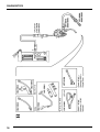
HARDWARE
USING COMPACT DISCS (CDs) (TESTBOOK 2)
TestBook reads vehicle repair information from
Compact Discs. These are referred to as CD’s.
TestBook can only read information from the CD, it
is not able to modify or save any information on the
CD. TestBook has an internal hard disc drive for
saving information.
TestBook must be resting on it’s rubber feet when
using CD’s. Always remove the CD from the disc
drive before moving TestBook long distances. This
is done by pressing the eject button on the CD drive
while the Welcome screen is being displayed on
TestBook.
NOTE: TestBook must be displaying the
Welcome screen before the eject button
on the drive will eject the CD. The eject
button will not operate at any other screen, nor
will it eject with TestBook switched off.
The top side of the CD is the side with labelling. The
digital information, however, is on the under side of
the CD, the shiny side without any words or graphics
printed on it. Therefore, it is very important that the
under side of the CD is kept clean.
CD’s must be kept away from heat. High
temperatures will damage them. Be sure to store
them appropriately.
NOTE: Handle Compact Disc’s by their
edges only! if the bottom (non-label) side
of the CD has visible dirt or fingerprints, it
will require careful cleaning before you can use
it. See CD Cleaning Procedure in a later section.
Remove any previous CD and, holding it by the
edges only, place it in a protective case.
27
HARDWARE
Operating the CD-ROM Drive
1. CD-ROM Drive
2. CD-ROM Ejector Button
3. CD-ROM Disk
28
HARDWARE
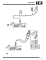
USING COMPACT DISCS (CDs) (TESTBOOK 1)
CD’s must be placed in a special caddy before
putting them into TestBook. NEVER attempt to place
a CD into the drive without a caddy.
Remove any previous CD and, holding it by the
edges only, place it in a protective case. If this is the
first time the caddy has been loaded, be sure to
remove any paper labels from inside the caddy.
The caddy is a special plastic case with a sliding
metal shutter on the bottom. To load a CD into a
caddy, carry out the following steps :
1. Press the two corners of the caddy at the tabs
labelled OPEN.
2. Lift the clear plastic cover to open the caddy.
Place the new CD into the caddy so that the labelled
side is facing up. The lettering on the CD should be
visible through the clear plastic.
29
HARDWARE
LOADING A CADDY INTO TESTBOOK 1
1. Ensure that TestBook is displaying the
Welcome Screen.
2. Open the door on the front, right-hand side of
TestBook to access the CD drive. The drive
has only one button on it, the eject button.
3. Press the eject button on the drive for at least
two full seconds. This is to make sure that
there is no CD in the drive already.
4. Ensure the new CD is label side up in the
caddy.
5. Open the door to the drive by gently pulling the
tab down and outwards.
6. With the CD label side facing up, slide the
caddy into the drive with the arrow edge
forward and the metal shutter side toward the
bottom.
7. Close both the CD drive door and the
TestBook access door.
Remember to always eject the CD and caddy from
the disc drive before removing TestBook from its
trolley for long periods of time. This requires
TestBook to be at the Welcome Screen.
30
CD CLEANING PROCEDURE
TestBook reads information from the bottom of the
CD, the side without any labelling printed on it.
If the bottom side of a CD should become soiled by
fingerprints, dirt or dust, the following cleaning
procedure will be necessary.
NOTE: Never use any type of solvent or
cleaner when cleaning a CD !
1. If the CD is in TestBook, press the eject button
and remove the CD, holding it by the edges.
This requires TestBook to be at the Welcome
Screen.
2. If the CD is not in TestBook, remove it from its
case and hold it by the edges only.
3. Find a clean, lint - free soft cloth. It must be
dry!
4. Wipe the CD only in a straight line, moving
from the centre to the edge.
5. Promptly return the cleaned CD to a protective
case or back into TestBook.
HARDWARE
BEGINNING WORK WITH TESTBOOK
Turning on TestBook 1
When you switch ON TestBook, a number of
self-test and set-up screens will automatically be
displayed on the screen.
The first TestBook screen you can use is the
Welcome screen. The welcome screen displays the
four key TestBook function buttons and the Control
Panel at the bottom of the screen containing a
number of smaller buttons.
31
HARDWARE
Turning on TestBook 2
Turn on power by toggling the power button to "|".
Verifying Correct Operation
After you power up TestBook, check the following to
determine if it is functioning properly:
1. Green indicator light positioned above the
on/off switch comes on.
2. Power up sequence appears on the screen.
3. TestBook main screen appears on the display.
The Welcome screen displays the four key TestBook
function buttons and the Control Panel at the bottom
of the screen containing a number of smaller
buttons.
32
NOTE: If TestBook is not connected to a
mains supply, it will start up from its
internal battery. This battery will not last
for the duration of most diagnostics. It is
important to check that the yellow LED is
illuminated, confirming connection to a mains
power supply.
HARDWARE
The four key function or mode buttons are as
follows:
TECHNICAL INFORMATION
When servicing Rover or Land Rover vehicles, this module provides
repair documents.In order to activate this function the relevant
Technical Information CD covering the vehicle that you are working
on must be installed in the TestBook CD drive.
DIAGNOSTIC SYSTEM
TestBook provides a range of diagnostic routines to guide you to a
technical solution. Touch this button to enter the booking and job
control (BJC) module. This is where you "register" the vehicle you are
working on by entering the vehicle identification number (VIN). The
vehicle diagnostics CD must be installed in TestBook to activate this
button.
TOOLBOX
The Toolbox provides various measurement tools, such as engine
analyser and a range of meters.
EXPERT TOOLBOX
Displays live monitor readings from ECU’s and other special tests
specific to the vehicle model.
33
HARDWARE
The highlighted Control Panel buttons at the bottom
of the Welcome screen work as follows:
SHUTDOWN
Touch this button when finished using TestBook. You should always
touch this, and await the "please turn off TestBook now" message on
screen, before turning OFF TestBook.
INTEGRITY TEST
Use this button only when you suspect a problem with TestBook. It
allows you to run tests on some of the TestBook hardware and
software to make sure it is operating properly.
TESTBOOK TUTORIAL
This button is used when running AutoCourse.
HELP
Allows you to view helpful documents with information about the
current screen or vehicle diagnostics.
HELP DESK
Pressing this button automatically prints a Help Desk Information
Sheet with certain sections already completed (See Help Desk
Section).
CONFIGURATION
This button allows you to customise TestBook with personal
preferences and information about your dealership. It also allows you
to set up additional hardware as well as install new versions of RDS
software.
34
HARDWARE
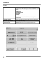
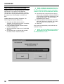
CONFIGURATION
This illustration shows the screen that TestBook
gives you in response to touching the Configuration
button.The buttons on this screen are as follows :
NOTE: the non-active (faded) buttons are
for future applications.
COLUMN 1
QWERTY
Touch this button to change between the conventional keyboard
layout - (known as QWERTY after its first six letters) - or a keyboard
based on alphabetical order. Choose whichever you find easiest to
use. This keyboard will appear automatically on screen whenever
TestBook requires you to input information, such as a VIN.
Size
This "slider" control varies the size of the touch-sensitive area within
each button on the screen. (For example, if you have very large
fingers, you may find it helpful to reduce this size to avoid overlapping
onto the adjacent buttons).
Sound
On or off.
Set Logging Level
TestBook activities can be recorded, or logged, at different levels of
detail.This is pre-set at minimum to avoid filling the memory, which
would slow down the operation of TestBook.
COLUMN 2
Enter Date and Time
TestBook needs to know the current date and time. If it is incorrect,
this is where it is adjusted. Do not, however, make adjustments
without first consulting the Help Desk; it is easy to damage the
age-protected software !
Set Configuration Password
An option to install security codes to prevent unauthorised re-setting
of TestBook configurations.
Align Touch
If the screen cursor doesn’t align with the area you touch, this facility
allows re-calibration to correct this.
35
HARDWARE
COLUMN 3
Enter Dealership Information
A facility for putting the dealership information into the TestBook
memory. Pressing this button brings up spaces numbered from one to
six. These relate to the following boxes on the Help Desk Information
Sheet.
Dealer Name
Corporate ID
Telephone Number
Fax Number
Contact 1
TestBook Serial/Model Number
This information is used when TestBook automatically prints a
Helpdesk form.
Install RDS Software
For the installation and updating of RDS software from the RDS CD.
Set Printer Type and Paper
Do not adjust these settings
Configure Network
Do not use unless you have the appropriate network in your
dealership
36
HARDWARE
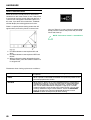
Touch Screen Calibration
Select the Align Touch button to recalibrate the
touch screen. TestBook instructs you to touch two
targets which will appear on the screen. Upon
completion of the calibration test, the new calibration
constants are stored on the hard disk. To ensure
that these new constants are deployed the TestBook
should be switched off (in the correct manner) and
restarted.
Select the calibrate option.
The following figure then appears on the display:
Several targets such as the following appear on your
screen.
Select Yes to save the screen coordinates as
chosen. Select No to repeat the touch screen
calibration.
Touch each of the targets that show on the display.
37
HARDWARE
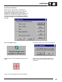
HOW TO INSTALL TESTBOOK SOFTWARE
TestBook software is updated periodically to include
new features. If you receive a new TestBook
software CD, it will need to be "installed" as follows.
("Install" means copying the software programs from
the compact disc onto TestBook’s internal hard
disc).
TestBook Software Installation Procedure - (for
Rover Diagnostic System (RDS) CD’s)
1. Place the new RDS software CD into
TestBook. For help with using CD’s, see earlier
section "Using Compact Discs".
2. From the Welcome screen, touch the button
labelled "Configuration"
3. At the Configuration screen, touch "Install RDS
Software".
4. You will see a pop - up window with a button
that reads "Install". Touch this button.
38
NOTE: TestBook is programmed to only
accept installation of either the current or
a numerically higher version of the RDS
software. You can not install obsolete software.
5. The software will automatically start copying
from the CD to TestBook’s internal hard disc. A
status indicator will monitor the progress of the
install, from 0 to 100%. The CD can not be
ejected during this process.
6. When the process is finished you will see the
message: "RDS set-up complete. The system
will now reboot to run the new version".
7. Touch OK.
The system will automatically restart with the new
software running.
NOTE: The current RDS version number is
displayed in the top right hand corner of
the Welcome screen.
HARDWARE
SCREEN FORMAT
Most screens displayed on TestBook have three
main sections; the TITLE AREA (top band), the
VIEW AREA (middle area), and the CONTROL
PANEL (bottom band).
Screen Format
TITLE AREA - this is the top portion of the screen. It
includes the Screen Title, displayed in the middle,
and the Screen Number, which is displayed at the
upper left- hand corner of the screen.
NOTE: Screen Numbers are needed to
identify screens if you have to call the
Help Desk.
The VIEW AREA is the middle area of the screen
where the technical information and other
documents are displayed.
The CONTROL PANEL at the bottom of the screen
contains eight buttons. These buttons change
somewhat from screen to screen. The fifth button is
always "HELP". Touch it at any time to get a
description of the current screen. If no help is
available for this specific screen, a standard RDS
help page will appear.
1. Title Area
2. Viewing Area
3. Control Panel
39
HARDWARE
HOW TO VIEW PICTURES
Some documents include pictures or illustrations,
sometimes on the same screen as text. If the picture
is too large to fit on the screen along with the text, a
"camera" icon will appear instead of the picture. In
this case, if you touch this camera icon, TestBook
will then display the missing picture on its own.
There is a special picture viewing screen that will
appear when you touch a picture or camera icon.
You can "Zoom In" to see a picture in greater detail.
Simply touch the area of the picture that you would
like to see close-up.
NOTE: You cannot "zoom" a second time.
1. Use these buttons to move picture UP and
down
2. Use these buttons to move picture LEFT and
RIGHT
3. When a picture has been enlarged using the
"ZOOM" facility, press this button to return it to
it’s original size.
The buttons when viewing a picture are as follows:PREVIOUS SCREEN
Returns you to the document you were viewing before you selected
the picture.
PRINT
When a printer is connected to TestBook, this prints the portion of the
picture displayed on the screen.
DETAILS
When active, it allows you to view related documents. If the button is
shaded grey (inactive), it means that there are no related documents
available. If the button is active and you touch it, a Pop-up window
with a list of related documents will appear. A pop-up is a smaller
screen that displays over the top of the current screen. You can then
scroll up and down using the arrow buttons. Touch the CONTINUE
button in the pop-up to view the highlighted document or touch
CANCEL to return to the picture you were viewing.
40
HARDWARE
The eight Control Panel buttons displayed when viewing Technical Information documents (derived from the Tech.
Info. CD), are as follows:
RETURN
This button returns you to the Select Return Destination menu.
(Described in the next section)
PREVIOUS SCREEN
Touching this button returns you to the previously displayed screen or
document.
CAMERA
Touching this button turns pictures on and off. TestBook navigates
through the software much faster with the pictures switched off.If you
are searching for a particular item,it may be worthwhile to turn the
pictures off until you find it, then turn them back on to study the item.
PRINT
This button allows you to print the current document. The option is
given to print now, which requires that a printer is connected, or save
the document to print it later.
HELP
Provides helpful information to assist with the current screen.
DETAILS
The details button when active, allows related documents to be
viewed (if the button is faded grey and inactive, it means that there
are no related documents available). When the button is active and
touched, a Pop-up window with a list of related documents will
appear, (A pop-up is a smaller screen that displays over part of the
current screen). The information can then be scrolled up or down
using the arrow buttons. Touch the CONTINUE button in the pop-up
to view the highlighted document or touch CANCEL to return to the
document that was being viewed.
NOTE: Pop-up windows, such as the details Pop- up,
disable the rest of the screen until you touch a selection
within the pop-up.
PREVIOUS PAGE
An alternative to the up arrow on the side of the screen, this button
will scroll backwards within the document by one page rather than
moving just one line as the arrow does. One page is equal to the size
of the View Area.
NEXT PAGE
Allows you to scroll forward in the document by one page.
Along with these buttons on the control panel, HOT SPOTS within
document can be touched to find more information. Any text or
graphic with a shaded box around it is a HOT SPOT.
41
HARDWARE
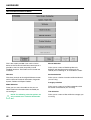
THE RETURN DESTINATION MENU
This is the screen provided if you use the ’return’
button on the Technical Information control panel. It
provides a menu to move you quickly around
TestBook functions. The buttons on this screen are
as follows.
Manual Selection
Welcome
Section Selection
This takes you back to the original Welcome screen
with its choice of Technical Information, Diagnostic
System, Toolbox and Expert Toolbox.
Takes you to a choice of sections within the Manual
you are using.
Takes you to a menu of Workshop Manuals,
Bulletins and other documents relevant to the
vehicle you are working on, all available on screen.
Category selection
Model Selection
Takes you to a menu of models so that you can
select Technical Information about the model you
are working on.
NOTE: The following selection options are
only available on a Technical Information
disc.
42
Takes you to a menu of available categories within
the section of the Manual you are using.
Title Selection
Takes you to a menu of titles within the category you
are using.
HARDWARE
INTEGRITY TESTS
If a problem is suspected with TestBook equipment
the Integrity Tests allow you to make sure your
equipment is working properly. Always run these
tests before calling the help line. They will allow
TestBook to determine if something is wrong with
the equipment. The Integrity Tests can only be
selected from the Welcome screen. If you are having
trouble getting back to the Welcome screen, you can
turn TestBook OFF, then back ON.
At the Welcome Screen, Integrity Test will appear as
a button on the control panel.
Touch the Integrity Tests button to view the Integrity
Tests menu. Use the up and down arrows on the
right - hand side of the scroll box to highlight your
selection. Then touch Continue on the control panel
to run the selected test. A new screen will appear
and the test that you selected will begin
automatically.
When running these tests, keep in mind that
electronic equipment can be affected by many
factors, including temperature and voltage spikes. If
any test appears to fail, always repeat it a second or
third time to make sure that it was not just a one time problem.
43
HARDWARE
How to Interpret the Results of the TestBook
Integrity Test
A series of diagnostics will be run to test the integrity
of TestBook hardware. A result will appear after
each test is finished. The tests are described as
follows:
Testing CD Drive
This test attempts to read from the compact disc that is currently in
the drive. If the CD can be read, the message "PASSED" will appear.
If "Fail or No CD Found" appears, this may be caused by one of the
following conditions.
• There is no CD in the drive (press the eject button to make sure).
• The CD is upside down in the caddy. (The label side should be
facing outwards).
• The CD is dirty or scratched. (see "CD Cleaning Procedure").
• The CD is defective. (Try using another CD. If it works, replace the
defective CD).
• OR, the drive may be malfunctioning. Check all the above and
retry the test.
Testing LAN Card
For units containing a correctly operating LAN card, the message
"Present" will appear.
Some units do not have a LAN Card, so that message is "Not
Present". This does not indicate an error if your unit does not include
the LAN card.
The LAN (Local Area Network) facility is intended for potential future
developments in dealership systems, and is not currently in use.
Checking for Parallel Device
This test will verify the connection to a printer. In many cases, no
printer will be connected and the message off-line or "Not Connected"
will appear. This is the normal message for a TestBook without a
printer. If a printer is present, properly plugged into TestBook,
powered OFF and On- Line, then the message "connected" will
appear.
If you have a printer plugged into TestBook, and the message "Off
Line or Not Connected" appears, check the following:
• Is the printer On-Line? The light on the printer labelled "On-Line"
should be lit. If not, press the On - Line button (on the printer).
• If the printer does not become on - line, try resetting the printer by
turning it OFF and then back ON. Touch BLACK or WHITE to
TEST LCD DISPLAY.
• If an error code appears on the printer, see the User’s Manual that
came with the printer for an explanation of the message.
• Check the cable between TestBook and the printer to make sure it
is plugged in securely.
• Check the Configuration Module to make sure TestBook is set up
to use the printer. The configuration screen is reached by touching
Configuration at the Welcome screen. See "Set Printer/Paper" in
the TestBook Configuration Section of details.
Touch BLACK or WHITE to
TEST LCD DISPLAY
After the above tests are complete, two new buttons will appear on
the control panel. These buttons, labelled Black and White, test that
the LCD screen is able to display all black or all white. When touched,
a solid black screen or a solid white screen will appear for a few
seconds and then go away.
BLACK- Displays a solid black screen
WHITE- Displays a solid white screen
If service appears necessary after repeating the test, contact the Testbook Help Desk to verify the problem.
44
HARDWARE
ROVING PROBE TEST
The Roving Probe Test will help uncover problems
with TestBook hardware. Run this test whenever you
suspect a problem with the Roving Probes.
Before running this test, make sure the Roving
Probes are plugged into the back of TestBook. Hold
both of the individual probes in your hands,
disconnected from any power source.
To run the test, move the scroll box at the RDS
Integrity Tests screen until Roving Probe is selected.
Then touch Continue. The Roving Probe Test
screen will appear and the test begins automatically.
How To Interpret the Results of the Roving Probe
Test
Two tests will be run to test the Roving Probe
hardware. A result will appear after each test is
finished. The tests are described as follows:
Touch Roving Probes Together
This test makes sure that the Roving Probes can complete a closed
circuit. you must hold the probes together for at least ten full seconds.
If either of the probes has an open circuit, it will appear during this
test.
Touch the Roving Probes together as instructed. You should see the
"PASSED" message appear.
If there is no response. check the following:
• Make sure the Roving Probes are securely plugged into the back
of TestBook.
• Check the cables for cracks or cuts.
• Check the fuse in the back of TestBook. Replace the fuse if
necessary with a 1 amp fuse of the same size. See "Fuse
Replacement" in the TestBook Installation Guide section.
Connect Roving Probes to a
Battery (1.5 to 12 Volts)
This test verifies that TestBook can measure voltage When you make
the connection to any battery rated between 1.5 and 12 Volts, a
readout of the voltage will appear in a box near the middle of the
screen. Be sure to connect the red probe to the battery " +" and the
black probe to the battery " -". When the voltage is measured steady
for ten seconds, the test will respond "PASSED". (To account for
strong or worn batteries, the test will PASS with any steady voltage of
between 1 and 18 Volts).
If your test battery does not have between 1.5 to 12 volts, or
TestBook cannot read the voltage, the message "FAILED" will
appear. Check the following:
Check that the Roving Probes are still securely plugged into
TestBook.
Check the fuse in the back of TestBook. Replace the fuse if
necessary with a 1 Amp fuse of the same size. See "Fuse
Replacement" in the TestBook Installation Guide section.
Check the battery using another tool to make sure that the voltage is
between 1.5 to 12 volts.
If service appears necessary, contact the Testbook
HelpDesk to verify the problem.
45
HARDWARE
LAN CONNECTION TEST
The LAN (Local Area Network) Connection Test is
not available yet. It will be added in a future revision
of the RDS software.
FILE SYSTEM
The File System Test checks for the presence of the
important RDS system files, and checks that they
are the correct size and date.
Errors here may sometimes be corrected by
re-installing the RDS software from the RDS CD, but
the errors may indicate a more significant underlying
problem. Contact Help Desk if re-installing the RDS
software fails to correct the error.
46
HARDWARE
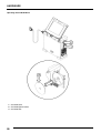
SERVICING TESTBOOK
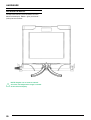
Display Panel
1. Disconnect cable from base unit.
2. Rotate display until you can remove it from the hooks.
47
HARDWARE
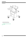
TestBook Shelf
1. Remove screws from shelf.
2. Remove panel from the trolley.
NOTE: The shelf covers the power
supplies
48
DIAGNOSTICS
CONTENTS
Page
HOW TO GET STARTED ......................................................................................... 1
DIAGNOSTIC CONTROL PANEL BUTTONS .......................................................... 2
MODEL YEAR VIN CHANGE POINTS - LANDROVER ........................................... 5
MODEL YEAR VIN CHANGE POINTS - LANDROVER ........................................... 6
CABLING GUIDE ...................................................................................................... 7
TESTBOOK ERROR CODES ................................................................................. 28
DIAGNOSTICS
HOW TO GET STARTED
Turn on TestBook, and wait for the Welcome screen
to appear after TestBook has automatically run
through a number of set up and self-test screens.
Select Disc for vehicle.
Locate the current compact disc for the vehicle you
are working on and insert into TestBook.
Select "Diagnostic System" from the Welcome
screen.
Select Vehicle and model year and touch
"Continue"
Enter VIN: key in the full Vehicle Identification
Number and touch CONTINUE. Check that all the
information on screen is correct for the vehicle and
touch CONTINUE again.
Select the Diagnostic Required
Touch the icon that relates to the vehicle system that
you wish to investigate.
Connect TestBook to vehicle - TestBook will tell
you on screen which connectors and cables you
need to connect it to the vehicle. For each item, you
will be given both the Hewlett Packard part number
(e.g. 29053-60006) and the LandRover part number
(e.g. DTC0007A). Use whichever of the two
numbers you prefer to locate each item on the cable
illustration poster. This will show you what the item
looks like and will tell you which box of the storage
system (e.g. A1) it is kept in. When you have
gathered all the required connectors and cables,
connect them to the TestBook as instructed, and
plug into the relevant diagnostic connector. (If you
do not know where this is located on the vehicle, use
the ’HELP’ screen facility).
Once all connections have been made correctly, you
can then follow the diagnostic instructions on
screen.
1
DIAGNOSTICS
DIAGNOSTIC CONTROL PANEL BUTTONS
These are the buttons displayed beneath the
diagnostic screens. As usual, if a button is shown in
faded grey, it is inactive. Note that the two buttons
on the right hand end of the panel vary according to
the diagnostic routine being followed.
The buttons are used as described below.
Abort
Retains the information associated with the current
document; gives you the choice of either cancelling
the operation or of temporarily suspending it and
returning to the Welcome screen.
Back Track
This button should NEVER be pressed.
Print
This button prints the screen you are viewing
(assuming printer installed and on-line).
Help
This button provides information to assist you with
the current screen or diagnosis.
2
Continue
This button will take you to the next screen in the
diagnostic procedure or test sequence. At the end of
a diagnostic/test procedure, the Continue button will
allow you to exit from the procedure, taking you to
what TestBook determines to be the next logical
point. This may be another diagnostic area or the
Welcome screen. It is important to be aware that this
need not be the end of your diagnostic options. You
are in control of the diagnostic procedure, TestBook
is only your servant. You may decide to continue
with other diagnostic activities, such as additional
TestBook testing, Sub-System Test, Real Time
Monitor, Toolbox, Toolbox meters, Engine System
Analyser or mechanical tests.
DIAGNOSTICS
For diagnostic routines requiring you to give Yes/No
answers to questions put up on screen, the two right
hand buttons appear as shown. Since "Continue"
would not satisfy the query,it is inactive (faded grey).
When toolbox meters are being used, one of the
right hand buttons becomes a "Change Range"
control.
NOTE: Sometimes during diagnostic
routines, TestBook loses communication
with the vehicle for no apparent reason. If
this happens, check the voltage of the vehicle
battery. TestBook will not work if the voltage is
NOT 11.7V OR ABOVE. Some diagnostics
involve leaving the ignition on for a long period
of time. This may cause the vehicle battery to
drop below the 11.7v working threshold.
3
DIAGNOSTICS
VIN PREFIX
LD
LJ
LH
LP
LN
LT
4
Land Rover Defender
Land Rover Discovery
Range Rover Classic
New Range Rover
Freelander
Discovery Series II
DIAGNOSTICS
MODEL YEAR VIN CHANGE POINTS LANDROVER
1993
1994
1995
1996
1997
1998
1999
MODEL YEAR VIN PREFIX
K
L
M
N or T
V
W
X
Freelander - 3 door - Petrol
-
-
-
-
-
601802
636916
Freelander - 3 Door - Diesel
-
-
-
-
-
602838
636953
Freelander - 5 door - Petrol
-
-
-
-
-
600477
636912
Freelander - 5 Door - Diesel
-
-
-
-
-
601683
636914
Defender 90 - V8
925128
933174
941071
974052
104631
145661
-
Defender 90 - Diesel
921214
930479
939976
969104
999222
138510
159810
-
932712
954528
-
995321
-
-
Defender 100 -V8
921563
930494
940670
969174
999300
138869
159821
Defender 100 - Diesel
921221
930494
939977
969103
999226
138480
159811
Defender 130
922169
930546
940050
969105
999375
138525
159831
Discovery 3-door - TDi
034314
064760
081993
163105
703237
746567
-
-
067271
081991
163290
703764
746945
-
Discovery 3-door - V8
034611
064773
082059
163115
704470
748516
-
Discovery 5-door - TDi
034315
064756
082004
163104
703238
746542
-
-
065253
082025
163176
703243
746566
-
Discovery 5-door - V8
034325
064755
082066
163112
703248
746545
-
Discovery 5-door - T16 MPi
055086
064757
083136
163257
703312
746590
-
Discovery 5-door - NAS
-
-
081994
166228
703241
746549
792672
Discovery Series II - 5 Door Tdi
-
-
-
-
-
-
200412
900012
Discovery Series II - 5 Door Tdi Auto
-
-
-
-
-
-
200430
900055
Discovery Series II - 5 Door V8
-
-
-
-
-
-
200420
900069
Discovery Series II - 5 Door NAS
-
-
-
-
-
-
200507
900000
Defender 90 - NAS
Discovery 3-door - Tdi Auto
Discovery 5-door - Tdi Auto
5
DIAGNOSTICS
MODEL YEAR VIN CHANGE POINTS LANDROVER
1993
1994
1995
1996
1997
1998
1999
MODEL YEAR VIN PREFIX
K
L
M
N or T
V
W
X
Range Rover Classic - V8
624781
-
647645
-
-
-
-
Range Rover Classic - 2-door
624826
-
-
-
-
-
-
Range Rover Classic - Diesel Gemini
624826
-
647654
-
-
-
-
Range Rover Classic - LSe
625164
-
647703
-
-
-
-
Range Rover Classic - NAS
624881
640266
657356
-
-
-
-
Range Rover Classic - NAS
LSe
624756
639964
647650
-
-
-
-
New Range Rover - 4.0
-
-
300190
316180
346796
376582
410484
New Range Rover - 4.6
-
-
300450
316182
346802
576871
410483
New Range Rover - Diesel
-
-
300699
316176
346749
376598
410482
New Range Rover - NAS
-
-
302054
318243
346800
377955
403796
6
DIAGNOSTICS
CABLING GUIDE
TOOLBOX
FUNCTION
DRAWING
REFERENCE
Engine & 4 Gas Analyser - Bear
Engine & 4 Gas Analyser - Crypton
Diesel & Smoke Meter - Crypton
Volt Meter
AC Volt Meter
Ohm Meter
Pressure
Vacuum
Current
DEFENDER
FUNCTION
Drawing J
Drawing J
Drawing J
Drawing H
Drawing G
Drawing K
MODEL YEAR
DRAWING
REFERENCE
Technical Information
Technical Bulletins
300 TDi
TD5
Diagnostic System
MEMS
GEMS
Security
Exhaust Gas Recirculation
ABS
TD5
96
95
99
99
➪
➪
➪
➪
Drawing C
Drawing X
Drawing R
Drawing N
Drawing Q
Drawing Q
7
DIAGNOSTICS
FREELANDER
8
FUNCTION
MODEL YEAR
Technical Information
Rave
98 ➪
Diagnostic System
ABS
EDC
Front Wash Wipe
Heated Rear Window
Lighting
MEMS 1.9
PDI
Power Distribution
Rear Wash Wipe
Security
SRS
Tail Door
Vehicle Config.
Warning Sounders
98
98
98
98
98
98
98
98
98
98
98
98
98
98
➪
➪
➪
➪
➪
➪
➪
➪
➪
➪
➪
➪
➪
➪
DRAWING
REFERENCE
Drawing Q
Drawing Q
Drawing Q
Drawing Q
Drawing Q
Drawing Q
Drawing Q
Drawing Q
Drawing Q
Drawing Q
Drawing Q
Drawing Q
Drawing Q
Drawing Q
DIAGNOSTICS
DISCOVERY
FUNCTION
MODEL YEAR
Technical Information
Repair Manual
Technical Bulletins
Electrical Trouble Shooting
Manual
Connector Library
Multi Point sensing
Single Point Sensing
300 TDi
95 ➪
95 ➪
96 ➪
Diagnostic System
Airbag SRS
Test
Load Box Simulation
95
95
Drawing M
Drawing V
Test
Load Box Simulation
➪ 97
➪ 97
Test
Load Box Simulation
97 ➪
97 ➪
95 ➪ 96
96 ➪
96 ➪
95
95 ➪ 96
96 ➪
Drawing M
Drawing Z
(Phone HelpDesk)
Drawing T
Drawing Z
(Phone HelpDesk)
Drawing D
Drawing Q
Drawing R
Drawing C
Drawing F
Drawing Q
Drawing U
Drawing N
Drawing Y
Drawing Q
96 ➪
96 ➪
Drawing R
Drawing R
Airbag SRS
Anti - lock Braking System
2.0
V8
V8
DRAWING
REFERENCE
Security
MEMS MPi
Engine Management 14CUX
GEMS
Break out box
Exhaust Gas Recirculation
Electronic EDC
Expert Toolbox
Market Programming
Transmitter Reprogramming
95 ➪
96 ➪
96 ➪
9
DIAGNOSTICS
DISCOVERY SERIES II
10
FUNCTION
MODEL YEAR
Technical Information
Rave
98 ➪
Diagnostic System
ACE
ATC
98 ➪
98 ➪
Auto GearBox
BCU & Transmission
Cruise Control
Diesel Engine
Gauges
Heated Screens
Lighting
PDI
Petrol Engine
Power Distribution
Security
SLS & ABS
SRS
Vehicle Configuration
Warnings & Sounders
Washers & Wipers
Windows & Sunroof
98
98
98
98
98
98
98
98
98
98
98
98
98
98
98
98
98
➪
➪
➪
➪
➪
➪
➪
➪
➪
➪
➪
➪
➪
➪
➪
➪
➪
DRAWING
REFERENCE
Drawing Q
No Cables
Required
Drawing Q
Drawing Q
Drawing Q
Drawing Q
Drawing Q
Drawing Q
Drawing Q
Drawing Q
Drawing Q
Drawing Q
Drawing Q
Drawing Q
Drawing Q
Drawing Q
Drawing Q
Drawing Q
Drawing Q
DIAGNOSTICS
RANGE ROVER CLASSIC
FUNCTION
Technical Information
Repair Manual
Technical Bulletins
Electrical Trouble Shooting
Manual
MODEL YEAR
93 ➪
93 ➪
96 (UK only)
Diagnostic System
Anti - lock Braking System
Air Suspension
Airbag SRS
3.9 & 4.2
Diesel Turbo
Test
Load Box Simulation
Engine Management 14CUX
Exhaust Gas Recirculation
DRAWING
REFERENCE
Drawing D
Drawing E
95
95
95 ➪
Drawing M
Drawing V
Drawing F
Drawing N
11
DIAGNOSTICS
NEW RANGE ROVER
FUNCTION
Technical Information
Repair Manual
Technical Bulletins
Electrical Trouble shooting
Manual
Connector Library
Diagnostic System
Air Suspension
Airbag SRS
Load Box Simulation
Airbag SRS
ABS
ABS
Auto Gearbox
BeCM
Cruise Control
GEMS
Breakout Box
Electronic Diesel Control
EMS 5.2.1
Heating, Ventilation and Air
conditioning
Horn
Instrument pack
Lighting
Mirrors
Seats
Security
Transfer Gearbox
Wash / Wipe
Windows
12
MODEL YEAR
DRAWING
REFERENCE
95 ➪
95
96
95 ➪
95 ➪ 99
95 ➪ 99
99 ➪
95 ➪ 99
99 ➪
95 ➪
99 ➪
95 ➪
99 ➪
95 ➪ 99
95 ➪ 99
95 ➪
99 ➪
95 ➪
95
95
95
95
95
95
95
95
95
➪
➪
➪
➪
➪
➪
➪
➪
➪
Drawing S
Drawing AB
Drawing Z
(Phone HelpDesk)
Drawing AB
Drawing Q
Drawing Q
Drawing Q
Drawing Q
Drawing Q
Drawing Q
Drawing Q
Drawing U
Drawing Q
Drawing Q
Drawing Q
Drawing Q
Drawing Q
Drawing Q
Drawing Q
Drawing Q
Drawing Q
Drawing Q
Drawing Q
Drawing Q
DIAGNOSTICS
13
DIAGNOSTICS
14
DIAGNOSTICS
15
DIAGNOSTICS
16
DIAGNOSTICS
17
DIAGNOSTICS
18
DIAGNOSTICS
19
DIAGNOSTICS
20
DIAGNOSTICS
21
DIAGNOSTICS
22
DIAGNOSTICS
23
DIAGNOSTICS
24
DIAGNOSTICS
25
DIAGNOSTICS
26
DIAGNOSTICS
27
DIAGNOSTICS
TESTBOOK ERROR CODES
TestBook RDS Error Codes
When using TestBook, you may occasionally
experience a situation where its operation is
interrupted by some kind of internal "hiccup", and an
"Error Code" appears on screen.
The Error code will appear in the format :
DTOOxxMX, where "xx" represents the number of
the code from 1 to 41; for example DTOO15MX is
shown on the table as error code 15. Against each
error code number there is a matching Action
instruction or instruction key number - refer to the
key below for details of the action to take.
The following tables tell you how to respond to each
error code.
Error code number
Action
21
3
1
3
22
3
2
3
23
3
3
3
24
4
1
Printer; check paper,
cables etc.
5
1
25
3
6
1
26
3
7
2
27
3
8
2
28
3
9
2
29
3
10
2
30
3
11
3
31
3
12
3
32
3
13
1
33
3
14
3
34
3
15
1
35
3
16
1
36
3
37
3
17
3
38
3
18
3
39
3
19
2
40
3
20
2
41
3
Action Key :
1. Restart TestBook and try operation again. If
this fails, try the operation on another vehicle. If
this still does not work, retry using a different
TestBook.
2. First, try operation again, without rebooting. If
this fails, reboot and try again. If this in turn
fails, try another CD. If this clears the problem,
then the original CD was causing the fault. If
the fault remains, then the problems in the
TestBook.
28
3. Fill in a Help Desk Information Sheet with all
details including the error code and contact the
Help Desk.
HELP DESK
CONTENTS
Page
DEALER CHECK LIST (BEFORE YOU RING) ......................................................... 1
LOCAL TELEPHONE NUMBERS ............................................................................ 2
TESTBOOK EXCHANGE SERVICE
HELP DESK ..............................................................................................................
EXCHANGE TIMES ..................................................................................................
DEALER RESPONSIBILITIES ..................................................................................
SERVICE LEVEL ......................................................................................................
TESTBOOK EXCHANGE MATRIX ...........................................................................
TESTBOOK CABLES ...............................................................................................
NOTES .....................................................................................................................
3
4
4
5
7
8
9
HELP DESK
DEALER CHECK LIST (BEFORE YOU RING)
Vehicle Details and Reported Fault
HELP US TO HELP YOU
This should include the exact vehicle model,
derivative, model year and VIN, plus any component
numbers or codes relevant to the area of the vehicle
being worked on. When combined with details of the
reported fault that you are trying to diagnose, this
may give TestBook engineers a short cut to a
solution based on previous experience.
If you have run into a problem when using TestBook,
and you are unable to resolve it by repeating the
procedure or by consulting TestBook literature
and/or the Help screens, the next stage is :
Fill in a Help Desk Information Sheet (an example is
shown on a following page)
Full details of Test being used
Telephone the Helpdesk using the information
sheet for reference
This information is vital to a TestBook engineer who
is trying to reproduce and solve the problem.
The Helpdesk may request you to fax this sheet to
them, therefore, it is vital that every section of the
Information Sheet is filled in accurately before it is
transmitted. If just one small detail is missed out or
changed slightly, it could make the difference
between getting a solution to your problem in
minutes - or days !
Some diagnostics can be reached via several
different paths. It is vital that the TestBook engineers
follow exactly the same diagnostic trail as you. It
would help a great deal if you made a note of each
screen where you made a decision, so the engineer
can follow exactly the same path.
For example:
TestBook has the capability to print a Help Desk
information sheet with certain sections automatically
completed. Pressing the Help Desk button on the
Welcome Screen automatically prints a Help Desk
sheet with six sections filled in. These six sections
are the ones taken from the Dealer Information
entered in Configuration.
They are :
1.
2.
3.
4.
5.
6.
Dealer Name
Corporate ID
Telephone Number
Fax Number
Contact 1
TestBook Serial/Model Number
If an RDS error occurs, the Fault Notification box has
a Help Desk button on it. Pressing this completes
the six sections mentioned previously and the
following sections aswell :
Data CD Reference Number
RDS Release Number
Screen Reference/Node ID
Error Message Displayed
The following sections MUST also be completed.
Select "Diagnostic System"
Select "Security"
Select "Locking/Unlocking"
Continue the path until you reach the screen with the
fault.
Full details of any difficulties you’ve had using
TestBook
It may be useful to TestBook engineers to know of
any difficulties that you have experienced when
using your TestBook.
Cabling Drawing Reference used
It is essential to use the right cables for a given test
procedure. By giving the details of the Cabling
Drawing Reference (e.g. A, AA etc. to Z, or 1 to 19)
that you used to assemble the TestBook connecting
cables, you will enable the TestBook engineers to
check that these are correct before looking for other
problems.
NOTE: If the TestBook screen on which
your problem occurred is one of those
that can be printed, please print it off and
fax it through to the Help Desk with your
Information Sheet . The more information you
can give the Help Desk, the faster they can help
you.
1
HELP DESK
LOCAL TELEPHONE NUMBERS
COUNTRY
HELPDESK
TRAINING
AFTER SALES
TECHNICAL SUPPORT
Australia
Fax
0417-270271
02-96872180
02-95855116
02-96872180
Belgium
Fax
02-7239911
02-7239926
02-7239911
02-7239911
France
Fax
01-39984077
01-39984072
Germany
or
fax
02131-938235
02131-938234
02131-938318
02131-938203
02131-938235
02131-938234
Greece
or
01-5912102
01-5912103
01-5912102
01-5912103
01-5912102
01-5912103
Italy
or
(Flying Doctor)
Fax
06-65771028
06-65771144
06-65771285
06-50085228
06-65771028
06-65771144
06-65771285
06-50085228
06-65771028
06-65771144
06-65771285
06-50085228
02131-938227
Japan
Fax
81-35478-6663
81-35478-7519
Land Rover
(North America)
Fax
1-800-5625824
1-800-5625824
1-800-5625824
301-731-9814
301-731-9814
301-731-9814
Netherlands
Fax
0347-366650
0347-376611
0347-366678
0347-366650
Portugal
Fax
01-940-6000
01-940-6092
91-678-9068
91-678-9011
91-677-1386
01926-646777
01926-647310
01926-647200
01926-647247
01926-646777
South Africa
Fax
Spain
U.K.
Fax
2
0027-11-3153314
0027-11-8052558
HELP DESK
HELP DESK
In the event that you experience a problem with the
performance of your TestBook you should report this
to the TestBook Help Desk. The Help Desk will carry
out a call qualification check, as per the TestBook
pro-forma, before recommending any exchange.
Replacement items that are covered by this support
agreement are:
TestBook
Printer
Cables
Trolley - power supplies only
Compact Discs (Diagnostic and RDS)
No items will be accepted for exchange without the
prior authorisation of the appropriate TestBook Help
Desk. The relevant TestBook Help Desk is as listed
below:
Area/Dealership
First line
Back-up
U.K. Land Rover
Gaydon
European
N.S.C./ Distributor
Gaydon
North America
Land Rover North America (LRNA)
Gaydon
Latin & South America,
Caribbean.
N.S.C./ Distributor
Gaydon
Japan
Land Rover Japan
Gaydon
Australia
Land Rover Australia
Gaydon
Rest of World
N.S.C./ Distributor
Gaydon
3
HELP DESK
EXCHANGE TIMES
TestBooks, Printers, Cables and Power supplies.
For calls received by the relevant Help Desk by
14.30 (local time) Dealerships in the countries of the
European Union, Austria, Switzerland, Norway,
U.S.A. and Australia will receive a replacement unit
on the following FEDEX working day.
For calls received by the relevant Help Desk by
14.30 (local time) Dealerships in the countries of
Eastern Europe will receive a replacement unit
within 48 hours of the following FEDEX working day.
For other countries FEDEX will use its best
endeavours to provide replacement units as soon as
possible from the date of the original request. The
expected exchange time will be given at the time of
authorising the exchange.
The only exception to the times quoted above is
where delays are caused by circumstances which
are beyond the control of FEDEX.
NOTE: These exchange times are subject
to clearance through local custom control.
CD’s
CD s will be despatched by first class post on the
next working day following receipt of request.
Returns
When an Exchange TestBook has been delivered,
you will find paperwork attached to the TestBook.
Within the paperwork, There is a contact number
that you must ring to arrange for a courier to collect
the faulty unit.
Cables and Power supplies need to be returned by
post in the next 14 days.
4
DEALER RESPONSIBILITIES
To ensure the smooth operation of this process and
the effective management of the limited TestBook
stocks there are a number of responsibilities that
must be observed by the dealer:
1. The instrument should be removed from the
trolley and available for the exchange.
2. Ensure that any C.D.’s are removed prior to the
receipt of the exchange unit.
3. The instrument should be in a safe and clean
condition for the engineers to work on.
4. When a fault is reported to the Help Desk
please report the fault as accurately as
possible and provide all the data required by
the pro-forma TestBook fault report form.
5. Contacting the courier to retrieve the faulty unit
must be done immediately. Failure to do so
could result in a charge to the dealer.
NOTE: Observing these responsibilities
will ensure that we maintain a speedy
exchange time, reduce stock shortages
and avoid potential increases in cost.
HELP DESK
SERVICE LEVEL
Printer
TestBook
The printer is covered by the support agreement. In
the event of failure you should report it through your
relevant TestBook Help Desk and they will arrange a
replacement.
TestBook Units that become in-operable due to
hardware or software failure will be exchanged
under the support agreement.
Hardware will be exchanged when the unit fails to
meet any area of the operating specification as
determined by the TestBook Help Desk.
Software failures will be in the following
circumstances:
i) The TestBook fails to reach the "Welcome" screen.
ii) The TestBook persistently fails to load and
execute data from the compact disc.
It does not, however, cover the inkjet printer
cartridge and it is recommended, therefore, that you
remove the cartridge prior to the exchange as the
replacement printer is not supplied with an inkjet
cartridge. New cartridges should be sourced locally.
Printer damage caused by the use of a non-HP or
"refilled" inkjet cartridges is specifically excluded
from the exchange service. Replacement units
provided under these circumstances will be
chargeable.
Cables
iii) Failures caused by the RDS operating system.
TestBook exchanges will not be covered by this
agreement where the software error is found to have
been caused by unauthorised attempts to modify
TestBook software, or loading of unauthorised
software.
Exclusions
Repair work resulting from the causes detailed
below are not covered by this exchange contract:
All TestBook cables are covered under this
agreement. Cables which fail should be immediately
reported through your TestBook Help Desk who will
arrange the replacement.
Exceptions
Where new cables are being supplied due to them
being reported as missing, lost or damaged through
mis-use then these will become a chargeable item.
In the event of this you must contact OMITEC
directly.
i) Repairs or modifications, including the removal or
damaging of integrity seals, that has not been
undertaken by Agilent Technologies.
ii) Damage caused by the improper use of TestBook
including unreasonable cosmetic damage.
iii) Usage of the unit outside the agreed
environmental conditions. (a copy of which can be
made available upon request).
In such cases Agilent Technologies will advise Land
Rover of the cost of repair and the repair will only be
undertaken with the prior written approval of Land
Rover. In these circumstances Land Rover reserves
the right to pass this cost onto the respective dealer.
5
HELP DESK
Trolley and Associated Power Supplies
The electrical and electronic parts of the trolley’s are
covered by this agreement i.e.
2 x power supplies
1 x printer power supply
1 x mains distribution point
Replacement parts will be shipped directly to the
dealer and the faulty parts should be returned by the
dealer to FEDEX within 14 days of the receipt of the
new part.
Mechanical parts are not covered and will only be
repaired subject to an additional charge.
Compact Discs
Damaged discs due to normal wear and tear can be
replaced through a request to the Help Desk.
6
HELP DESK
TESTBOOK EXCHANGE MATRIX
Item
Contact
Delivery
Method
Return Method Notes
TestBook
Help Desk
Courier
Courier
Courier will collect once contacted
Printer
Help Desk
Courier
Courier
Courier will deliver and collect at the
same time.
Cables
Help Desk
Courier
Post
Dealer must return the faulty cable
within 14 days of the receipt of the
new cable
Adapters
Help Desk
Courier
Post
Dealer must return the faulty
adapter within 14 days of the receipt
of the new adapter.
Trolley Power
Supplies
Help Desk
Courier
Post
Dealer must return the faulty part
within 14 days of the receipt of the
new one.
Compact Discs
Help Desk
Post
Post
Dispose of safely, locally or return
to the TestBook Help Desk
7
HELP DESK
TESTBOOK CABLES
Land Rover Part No.
Supplier Part No.
DTC0006A
29053 - 60002
DTC0007A
29053 - 60006 or
29053 - 60011
DTC0008A
29053 - 60004
DTC0013A
27091 - 60006 or
29053 - 60012
DTC0051A
29055 - 60016
DTC0063A
29055 - 60018
5063 - 3238 or 5063 3240
DTT0002A
29053 - 60007
DTC0033A
29053 - 60019
DTC0036A
29053 - 64006
DTC0057A
DTC0061 A
29053 - 60024
DTC0062 B
29053 - 60025
DTC0064 A
29053 - 60026
DTC0020A
29055 - 60002
DTC0021A
29055 - 60003
DTC0022A
29055 - 60004
DTC0023B
29055 - 60015
DTC0025A
29055 - 60008
29053 - 64001
DTC0016A
29053 - 64003
DTC0026A
29053 - 60020
DTT0001A
29053 - 60005
8
Omitec Instrumentation Ltd.
Hopton Industrial Estate
London Road
Devizes
WILTS
SN10 2EU
TEL: (+44) 01380 729256
FAX: (+44) 01380 729277
HELP DESK
NOTES
9
HELP DESK
Tel: +44 (0) 1926 646777
Fax: +44 (0) 1926 647310
HELP US TO HELP YOU
Please ensure you have the following information to hand BEFORE you contact the Help Desk.
.
Dealer Name and Address: (1)
Corporate ID: (2)
Date:
Telephone No: (including area code) (3)
Fax No: (including area code) (4)
Contact 1: (5)
Contact 2:
TestBook Serial/Model No: (located on rear of screen) (6)
Screen Reference/Node ID: (alpha-numeric data displayed top left
hand corner of the screen).
Data CD Ref No: (printed on CD/displayed on welcome screen
under "i" button).
RDS Release No: (displayed top right of screen)
Vehicle details: (including model/engine/transmission/derivative)
Model Year:
VIN:
Reported fault with the vehicle:
Full details of test being used:
Full details of problems encountered using TestBook:
Other Comments:
Error message displayed:
Cabling diagram used: