1
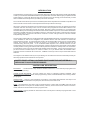
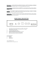
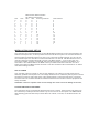
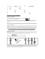
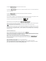
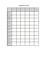
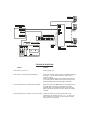
MAD1 DMX CONTROLLER
USERS MANUAL
ISSUE 5
INTRODUCTION
Congratulations on purchasing your new controller. We have endeavoured to design quality and reliability
to offer you an advanced Multi Media DMX-512 programmable controller that will give you optimal results
at low budget. It is the most advanced unit for its size and price. We strongly recommend that you take
time to read this manual fully before you attempt to use the controller.
The controller is a dual microprocessor controlled system that is fully DMX-512 and MIDI compatible. The
same controller can be used to control all present and future products in the range.
All scenes, chases and programs can be selected and controlled from the easy-to-operate touch panel
controller and each and every scene can be accessed and programmed via the MIDI interface. The
controller also has a MIDI file recorder and player with MTC chase lock allowing for a complete fully
automatic MIDI synchronized light show without the need for a MIDI sequencer. The controller is based on
10 banks on 6 DMX channels. It is possible to have a 4 channel scanner and a 2 channel colour changer
on the same bank by using all six channels so a total of 10 colour changers with 10 scanners could be
independently controlled.
The Controller is designed to be used together with standard MIDI keyboards. It uses 2 MIDI channels out
of the standard 16 and can be assigned to any address with the user DIP switches. It features 60
preprogrammed scenes, 12 preprogrammed chases, 60 programmable scenes and 12 programmable
chases. The maximum number of steps per chase is 14. Sequences or individual scenes can be
controlled using the front panel, or via a standard MIDI keyboard. The controller features a touch
sensitive spill proof control panel, a proportional X/Y joystick normally used for pan and tilt, 4 linear sliders
normally used for colour, gobo and two other effects plus a linear slider for chase speed. The construction
is a standard 19” rack mount 2U unit with grab handles and power switch. On the rear panel there is a 3
pin XLR connector for DMX output, 1/4” Jack for Audio in, 2 x 5 pin DIN for MIDI IN and MIDI THRU.
120/240V selector combined IEC mains Inlet, a SMPTE socket (for future use) and the MIDI selector
switches.
Once again we would like to thank you for purchasing our controller and we are sure that it will provide you
with easy operation and tremendous control power.
SAFETY FIRST : LETHAL VOLTAGES EXIST INSIDE THE UNIT, REFER ALL
SERVICING TO QUALIFIED PERSONNEL.
CONTROLLER DESCRIPTION
BLACKOUT : The BLACKOUT key will force all DMX channels to ‘0’ and will stop all programs and
chases currently running.
SCENE-CHASE-PROGRAM : This key selects the mode of operation between SCENES, when
programming new scenes, CHASE, when programming a chase, and PROGRAM, when running a built in
pre-program.
CROSS FADE : This key, when activated, will create a cross fading effect between the steps in the
program / chase that will result in very slow pan, tilt movement, and colour scroll
SAVE : By pressing this key during scene programming the current state of all DMX channels can be
repeatedly saved to a 40 year non volatile memory. This key is also used to save chases of scenes in
chase mode and to enter midi file record in program mode.
AUTO CHASE : This key will start an automatic continuous sequence of all the pre-programmed or user
programmed chases.
BANK SELECT : This key selects one of 10 banks of scenes or 1 of 2 banks of chases or 1 of 2 banks of
pre-programs. The selected scene bank will show in the display as level 1 (L1) through level 9 (L9) and
finally (LA). Chase banks show as (C0 , C1). Pre program banks show as (P0, P1).
HEAD UP/DOWN : By pressing the UP or DOWN keys you can select the fixture you want to address.
The ‘OP’ position selects every other fixture and the ‘AL’ selects all fixtures for multiple programming at
one step.
1 - 6 Keys : During SCENE mode these keys will address the scene number you choose at the selected
bank level (L1-LA). During CHASE mode these keys will select the chase you want to run. During
PROGRAM mode they will select the built in pre-programs.
CHASE SPEED : This slider will change the chase rate of the selected program/scene. At the minimum
setting (0), the programs/scenes will become music activated and the music L.E.D (Light emitting diode)
will flash at the rate of the audio bass beat.
REAR PANEL DESCRIPTION
1
1234567-
2
3
4
5
IEC Mains Inlet with Combined fuse and 120\230 mains selector.
The following connectors are SELV (Safe Extra Low Voltage)
SPMTE input, phono socket.
1/4” Mono Jack Skt. Audio input.
Female XLR DMX Output Connector.
Midi Input Connector. Female 5 PIN 180 deg DIN.
Midi Thru Connector. Male 5 PIN 180 deg DIN.
MIDI Channel selector switches (4 dip sitches)
XLR CONNECTOR
Pin Configuration
1
Ground
2
DMX Neg (-)
3
DMX Pos (+)
END TERMINATOR
100 Ohm resistor across pins 2 & 3
6
7
Sw1
0
1
0
1
0
1
0
1
0
1
0
1
0
1
0
1
Sw2
0
0
1
1
0
0
1
1
0
0
1
1
0
0
1
1
Midi Channel Selector Switch
Dip Switch Configuration
Sw3
Sw4
Pre Prog Channel
0
0
1
0
0
2
0
0
3
0
0
4
1
0
5
1
0
6
1
0
7
1
0
8
0
1
9
0
1
10
0
1
11
0
1
12
1
1
13
1
1
14
1
1
15
1
1
16
User Channel
2
3
4
5
6
7
8
9
10
11
12
13
14
15
16
1
INSTALLATION AND SET UP
The controller can be interfaced directly to other Multi Media products such as music keyboards, foot
switches and sequencers, via the 5 pin MIDI connectors at the back panel. The four DIP switches at
the back panel set the MIDI channel you wish to use. There are 16 MIDI channels you can use and
the controller requires 2 channels to control all its features. The channel that MIDI switch is set to, is
used for cueing pre-programs and built in scenes. The MIDI channel + 1 is for cueing your own
scenes and chases. To figure out the MIDI channel follow the binary sequence from 0000 to 1111
when SW1 is the LSB and SW4 is the MSB. Follow your MIDI instrument’s instruction on how to
select and configure its MIDI interface channels. Note the controller must be switched off / on before
new switch settings are read.
SET UP POWER
Your controller is able to operate on 120v or 230v 50/60hz. This is factory set and should only be
altered by qualified service personnel. The voltage selected can be checked by looking at the unit with
the earth pin at the top and noting which of the voltage ratings on the fuse holder is the correct way
around to read. The controller should be installed so that the socket outlet is near the equipment and
easily accessible.
CAUTION :- Failure to operate at the correct voltage will result in serious damage to the unit! .
FIXTURE DMX SWITCH SETTINGS:
The controller is factory programmed with 60 scenes and 12 chases. These scenes and chases can
be accessed by a midi input and the chases only can be run from the front panel. The DMX address
table following gives the ideal setup to make best use of these, of course, not all effects have to be
used.
HEAD SCAN411
1
2
3
4
5
6
7
8
9
10
c001
c007
c013
c019
QSCAN/
COL211
SCAN611ARP
c003
c009
c015
c021
c025
c031
c037
c043
QCOL
STAR311/QSTAR/
SATR511ARP
c027
c033
c039
c043
c050
c056
OPERATION AND PROGRAMMING
MODES OF OPERATION
Your controller has three basic modes of operation selected
from the SCENE-CHASE-PROGRAM key:
Scene: This mode should be selected when you intend to create new scenes. Press the function key
until the ‘scene’ indicator is lit. See the ‘Operation and Programming’ section for programming
procedures.
Chase: This mode should be selected after you have stored several scenes and you like to create a
chase. Press the function key until the ‘chase’ indicator is lit. See the ‘Operation and Programming’
section for more details.
Program: In this mode you can run the pre-programmed chases by pressing one of the number keys
on the control panel touch pad. Access this mode by pressing the function key until the ‘program’
indicator is lit. When you turn on the controller for the first time the display will read ‘P’ for program,
and you will be in the ‘program’ mode. You can also enter midi file record mode by pressing the SAVE
key. Note the PRE programs are optimised for use as detailed in the DMX settings table.
RUNNING A PROGRAM
When your controller is first switched on, the display BLACK OUT indicator will light and the ‘program’
indicator will be on. You are now in the program mode and you can select any one of the six built in
pre-programs by pressing one of the number keys (1-6) on the control panel.
Now press the BLACK OUT
touch pad to turn on the lights.
There are five sliders and a joystick on the controller as follows:
DMX
CH2
DMX CH1
CHASE SPEED
DMX CH3
DMX CH4 DMX CH5 DMX CH6
To adjust the chase speed use the ‘CHASE SPEED’ slider while the program is running. When the
slider is at the minimum (‘0’) position the controller will become sound activated and you will notice
the sound L.E.D ( ¶ ) flashing to the beat of the music.
Pressing the CROSS FADE
key will create a ‘smoother’ effect.
Pressing the AUTO CHASE key will start the automatic sequence where all the pre-programs will
chase continuously.
Pressing the BLACK OUT key again will stop the program and will turn off the lights.
CREATING A SCENE (stage 1)
The controller is capable of 60 programmable scenes and the first step before any program can be
entered is to create several scenes. Follow the procedure below to create a scene.
Press the function key until the scene indicator is lit:
Select the head you want to address with the HEAD UP & HEAD DOWN keys.
After you view the unit number in the display window go ahead and adjust the DMX channels using the
slider and joystick levels to the desired level.
* Note: It is important to move the sliders upwards until they engage and activate the function.
Repeat the above for each head. The current head will be displayed in the display window. For quick
programming you can select ‘AL’ or ‘OP’ . ‘AL’ will move all the heads in the same direction. ‘OP’ will move
every other head in an opposite direction. Use the ‘HEAD UP’ or ‘HEAD DOWN’ keys until the display
shows ‘AL’ or ‘OP’.
SAVING A SCENE (stage 2)
After you adjust all the parameters, to save the scene press the SAVE key.
When you notice all the number L.E.D’s flashing, select one of the six numbered touch pads (see above)
to store the scene you created. If you selected number one (1), the scene will be stored as scene number
one (1) in the currently selected scene bank (L1 - L9 and LA).
When you are in scene bank one (1) you will note the display flashes L1
When you use all six scenes at this bank you can select another bank with the BANK SELECT key
where you have another six scenes. The display will then show L2 and each succesive press will
increment the banks.
Note: Alternatively you can press the key on the midi keyboard to
where you want to save the scene.
! There is a total of 10 levels (60 scenes). Repeat stages 1 and 2 to create more scenes
! It is recommended that you fill the ‘Memory Map’ on the next page to remind you of ‘looks’
you created and serve as a reference during programming.
MEMORY MAP
1
L1
L2
L3
L4
L5
L6
L7
L8
L9
LA
2
3
4
5
6
CREATING AND SAVING CHASE
Press the function key until the chase indicator is lit
Press the BANK SELECT key to select the chase bank to where you want to save the chase.(C0 to C1).
You do not need to do this if you have a midi keyboard.
Press the SAVE key. All the L.E.D’s will flash.
Press one of the six number keys 1 to 6 to select a chase number or press the key on the midi
keyboards where you wish to save the chase (TOP 12 keys).
Press one of the six number keys 1 to 6 along with the BANK SELECT key to select the scenes you
want to include in this chase and in the order you want. (MAX. 14). Or press the scene keys on the midi
keyboard.
Press the SAVE key when done and the chase will run.
As with the pre-programs the chase speed may be varied and the ‘CROSS FADE’ can be used. The
desired speed may be saved with the chase by pressing the ‘SAVE’ key again.
! There are a total of six chases. ! Repeat stage three (3) again to create another chase.
When you have finished creating scenes and chases it is advisable that you protect your data by
locking the memory of the controller. You can lock/unlock the memory by pressing ‘BLACK OUT’
followed by the number pad: 6 + 6 + 6
(Save Light lit = locked ).
MIDI AND MULTI MEDIA
Your controller can interface directly to other Multi Media products via the 5 pin MIDI connectors. It can be
used in conjunction with music keyboards, foot switches and sequencers such as Enigma and Cubase. A
sequencer is only required for complex editing of a lightshow. This lightshow can then be recorder by the
controller and the sequencer is not required any more. For simple lightshows, a sequencer is not required
at all. The design of the controller scenes and chases fit perfectly to a standard 49 key MIDI keyboard
such as GMK49 or Roland PC100. On these keyboards the first 5 octaves of the keyboard (the first 60
notes) will access directly the 60 scenes, the next octave (61 - 72) will activate the chases. The last key
(73) controls the ‘Black Out’. (Note transpose UP and DOWN on the midi keyboard is used to make the 4
octave keyboard cover 6 octaves).
A keyboard can operate up to 8 different Controllers addressed on different MIDI channels. Set the MIDI
switches to the MIDI channel you wish to use (Refer to the keyboard manual). The channel that MIDI
switch is set to, is used for cueing pre-programs and built in scenes. The MIDI channel + 1 is for cueing
your own scenes and chases.
To put the controller into MIDI file record, simply press the SCENE-CHASE-PROGRAM key to
PROGRAM and press the SAVE key. When the controller sees the MIDI TIME CODE via the MIDI IN port,
it will lock to it, (NOTE only 1st 8 mins of MTC are allowed). The controller will finish the record when the
MTC signal is stopped. To play the MIDI file back, simply start the MTC source up again and the controller
will lock to it.
Following is a simple set up for a light show. One of the audio tracks is used as a time code track. The TS1
can be used to record this onto the 4 track tape player before the audio is recorded onto the 4 track. The
TS1 converts the audio SPMTE onto the tape to MTC for the controller. When the controller is in midi file
record mode, just hit the required midi notes on the midi keyboard in time with the music and the controller
will record them relative to the time position.
TROUBLE SHOOTING
FAULT
CHECK
Fixture does not turn on
Check power line
Fixture does not respond to DMX signal
Check the control cable from the controller and along
the chain. Look for bad connection, bad cable or
incorrect wiring.
Check the addressing and personality DIP switches
on the back panel. Make sure the unit is set up and
addressed properly and according to the table.
The controller does not respond to the MIDI.
Make sure that your MIDI instrument corresponds to
the right MIDI channel you selected via the DIP
switches at the controller back panel. Consult your
MIDI instrument manual on how to select your MIDI
channel.
The controller does not store your scene/chase. Unlock the memory by pressing ‘BLACK OUT’
followed by the number pad ‘6’ + ‘6’ + ‘6’. After you
have entered your scenes, lock the memory again
using the same sequence.
TECHNICAL
Power Consumption: <0.2 Amp @ 120V & 230V
Operating Voltages: User selectable via 120/230V selector switch from back panel.
Fuse : Internal on PCB
1 x T-250VAC-500mA 20mm GLASS
Mains within in IEC inlet 1 x T-250VAC-100mA 20mm CERAMIC.
Connectors:
1/4” mono Jack for Audio in. (SELV)
2 x 180 deg 5 pin din for MIDI IN and MIDI THRU (SELV)
1 x XLR skt for DMX out (SELV)
IEC fused mains inlet with 120\230V selector switch
1x phono socket for SMPTE input (SELV)
Control Protocol : Industry standard 1990/91 version DMX 512.
MIDI Interface: MIDI IN and MIDI THRU interface for operation via standard keyboard, Midi foot switch,
Sequencer, MTC source.
Implements the following :Midi Note on
Midi Progam change.
Midi time code chase lock, first 8 miniutes.
Size: 19” Rack mount with rear box 17” x 5” x 3.25”
Weight: 1.5Kg
Scenes: 60 programmable, 60 pre programmed.
Chases: 12 Programmable, 12 pre programmed.
Audio: Line voltage 1V Pk to Pk to 3V Pk to Pk.
Memory: 40 Year. No battery required.
Due to continuous improvements, specifications may change without prior notice.
SELV = Safety Extra Low Voltage
GUARANTEE
Mad Lighting Ltd guarantee the controller to the original purchaser to be free from defects in workmanship
or materials for a period of 2 years in the UK and 1 year in other countries from the date of purchase
provided the registration slip is returned within 14 days of purchase. This guarantee covers parts and
labour. Proof of purchase must be provided by you for all guarantee repairs. This will usually be in the form
of a dated receipt. In cases where no proof of purchase exists, date of manufacture will be used to
determine the commencement of the guarantee period.
The guarantee does not cover any damages created through accident, miss-use, abuse, neglect,
improper installation or alteration other than by Mad Lighting Ltd or its authorised representatives. Mad
Lighting Ltd is not responsible for damages or loss during shipment.
Repair or replacement will be made at the option of Mad Lighting Ltd. Mad Lighting Ltd or its agents will not
be liable for any incidental or consequential damages for breach of any express or implied guarantee on
this product. Except to the extent prohibited by applicable law, any implied guarantee of merchantability or
fitness for a particular purpose on this product is limited to the duration of this guarantee.
Shipping for Repair
Never return a piece of equipment for repair until you have obtained a ‘Return Authorisation Number’
(RA #) from your dealer or distributor. Returned equipment will not be accepted without this. Shipping
costs are the purchasers responsibility. Mad Lighting Ltd will cover one way shipping costs for guarantee
repairs within Europe. Never ship returns to us freight collect. Expedited deliveries are not covered under
Guarantee.
GUARANTEE REGISTRATION SLIP.
SERIAL NO. __________
SUPPLIED BY :
ADDRESS :
DATE PURCHASED ________
YOUR NAME
ADDRESS:
TO BE RETURNED WITHIN 14 DAYS OF PURCHASE.