1
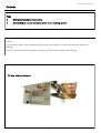
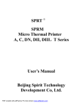
Issue 1 BC Box Modification with Port Isolation Installation Manual Instructions for :BC Box Modification with Port Isolation Models : KS8-CMB-P-V-G1 / KS8-CMB-P-V-GB1 / KS8-CMB-P-V-GA1 / KS8-CMB-P-V-HA1 / KS8-CMB-P-V-HB1 For safe and correct use please read this installation manual and use in conjunction with the BC Box installation manual supplied by Mitsubishi Electric. Modified on behalf of MITSUBISHI ELECTRIC UK BC Box with Port Isolation Contents Page 3 Ball valves installation instructions 4 Connecting to unused isolation valves on an existing system The Mitsubishi Electric BC box should be installed in accordance with the installation instructions supplied with the unit. Care should be taken, when installing the BC box with port isolation, to protect the fitted ball valves from damage. DO NOT use the ball valves as handles for lifting or as mechanical support for the BC box. BC box with port isolation 2 BC Box with Port Isolation BC Box with Port Isolation - Installation Instructions When installing ball valves it is very important to note that when applying heat it should only be for a matter of seconds, not minutes. For soft soldering - Use oxygen-acetylene or equivalent type heating torches. For Silver Brazing - ONLY use an oxygen-acetylene heating torch capable of raising the temperature of the tube socket to the required brazing temperature within a time period of approximately one minute. New Installation IMPORTANT : Before installing the valve in the line, remove the schrader valve and turn the stem to the open position. Recommended procedure for silver brazing to copper tubing Cut tube ends square. Remove burrs. Remove all grease and oil from joint area and clean the outside of the tube with emery cloth. Insert tube to full depth of connection socket to ensure proper fit. Withdraw tube half way out of the socket, apply brazing flux evenly over the tube and outside of the socket and reinsert tube. Wrap a wet cloth around the valve body and bonnet, but away from the socket to be brazed. With the torch adjusted to a reducing flame apply heat to the entire circumference of the tube over a distance of approximately 15mm to 50mm from the valve socket to expand the tube and carry the heat down inside the socket. Continue heating until the flux on the tube becomes liquid at which time the flame should be directed on the valve socket as well as the tube but pointed away from the valve body. When the flux has become very fluid and watery in appearance apply the brazing alloy against the heated tube starting at the bottom of the junction of the tube and valve socket. If the joint is at the proper temperature the brazing alloy will flow quickly around the tube and into the socket. If the alloy does not flow readily continue heating until the proper temperature is reached. Remove the flame as soon as the liquid brazing alloy has covered the entire joint and penetrated down to the socket. After a few seconds when the alloy has set, apply a water soaked cloth to the joint and to the entire valve to carry away excess heat as quickly as possible and remove residual flux. When the temperature has been lowered remove all excess flux using a wire brush if necessary. Fully open valves, ensure caps are refitted to Schrader valves and valve shaft. Existing Operational System / Pipework If additional fan coils are to be fitted or other work carried out after the initial installation before making alterations ensure that both the relevant ball valves on the circuit to be worked on are fully closed. Connect gauge lines to the relevant Schrader valves and recover all refrigerant to F-Gas guidelines. Once works are carried out pressure test and fully evacuate the pipe lines to F-Gas guidelines. If additional pipework has been added to the liquid line additional refrigerant will need to be added at the outdoor unit. Please refer to the PURY City Multi service manual to calculate the additional quantity required. 3 BC Box with Port Isolation BC Box with Port Isolation - Installation Instructions Connecting to unused isolation valves on an existing system If additional fan coils are to be fitted or other work carried out after the initial installation before making alterations ensure that both the relevant ball valves on the circuit to be worked on are fully closed. Cut tube ends square. Remove burrs. Remove all grease and oil from joint area and clean the outside of the tube with emery cloth. Insert tube to full depth of connection socket to ensure proper fit. Withdraw tube half way out of the socket, apply brazing flux evenly over the tube and outside of the socket and reinsert tube. Wrap a wet cloth around the valve body and bonnet, but away from the socket to be brazed. With the torch adjusted to a reducing flame apply heat to the entire circumference of the tube over a distance of approximately 15mm to 50mm from the valve socket to expand the tube and carry the heat down inside the socket. Continue heating until the flux on the tube becomes liquid at which time the flame should be directed on the valve socket as well as the tube but pointed away from the valve body. When the flux has become very fluid and watery in appearance apply the brazing alloy against the heated tube starting at the bottom of the junction of the tube and valve socket. If the joint is at the proper temperature the brazing alloy will flow quickly around the tube and into the socket. If the alloy does not flow readily continue heating until the proper temperature is reached. Remove the flame as soon as the liquid brazing alloy has covered the entire joint and penetrated down to the socket. After a few seconds when the alloy has set, apply a water soaked cloth to the joint and to the entire valve to carry away excess heat as quickly as possible and remove residual flux. When the temperature has been lowered remove all excess flux using a wire brush if necessary. Once works are carried out pressure test and fully evacuate the pipe lines to F-Gas guidelines. Fully open valves, ensure caps are refitted to Schrader valves and valve shaft. Additional refrigerant will need to be added at the outdoor unit. Please refer to the PURY City Multi service manual to calculate the additional quantity required. 4 BC Box with Port Isolation 5 Please be sure to put the contact address/telephone number on this manual before handing it to the customer. MITSUBISHI ELECTRIC UK MITSUBISHI ELECTRIC UK, TRAVELLERS LANE, HATFIELD, HERTFORDSHIRE, AL10 8XB 6