1
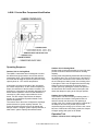
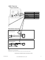
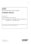
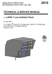
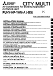
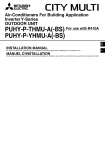
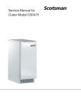
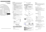
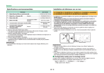
2013
TECHNICAL & SERVICE MANUAL
Model
LAHK-1 Low Ambient Hood
For use with CITY MULTI® PUHY-P-T/Y(S)KMU, PURY-P-T/Y(S)KMU,
and PURY-HP-T/Y(S)KMU Series outdoor units
4000292
Manufactured for Mitsubishi Electric US, Inc.
December 2013
© 2013 Mitsubishi Electric US, Inc.
1
LAHK-1 Control Box Component Identification
Operating Sequence
Outdoor Unit in Cooling Mode
The LAHK-1 low ambient hood is designed to reduce
the airflow through the outdoor units as the ambient
temperature drops. This maintains the head pressure
at a level that will allow the system to perform at 100%
o
capacity down to -10 F outdoor temperature.
A thermistor mounted on the side of the unit senses
the outdoor temperature. As the outdoor temperature
drops, the resistance of the thermistor increases. The
thermistor is connected to the specially designed circuit
board and the resistance value from the thermistor is
converted to a DC voltage output within the circuit
board. This DC voltage output drives the damper
actuator to a predetermined position based on the
outdoor temperature.
The inverter driven fan motor will adjust the discharge
pressure based on system capacity demand. The
motor will speed up and force more air through the
damper if there is a higher system capacity demand, or
slow down if system capacity demand decreases.
Outdoor Unit in Heating Mode
Heating mode requires the damper be in the fully open
position to allow full airflow and maximum heating
capacity.
Heating mode automatically deactivates the kit through
an interlock relay. The coil for this relay is tied into the
reversing valve connection on the outdoor unit. When
the unit switches to heating mode, the reversing valve
is energized. This in-turn energizes the interlock relay.
When the relay is energized, the normally closed
contact opens. By opening this contact, the power to
the transformer and control board is interrupted, this
allows the damper to spring to the full open position.
Outdoor Unit in Defrost Mode
If the outdoor unit will be running in heating mode, a
defrost period is inevitable. During defrost the low
ambient controls see this as the unit operating in
cooling mode. If the outdoor temperature is below 50 F,
the damper will close to a position equal to that
required during the cooling cycle. Once the unit comes
back out of defrost and into heating mode, the damper
will again spring wide open for full airflow.
Operation Test
Outdoor unit must be in cooling mode
December 2013
© 2013 Mitsubishi Electric US, Inc.
2
All hoods and damper controls are tested at the factory
before shipping. To perform an operational test once
the installation has been completed, follow the steps
below.
Operation testing when the outdoor ambient is
ABOVE 50°F
1. Turn on power to the outdoor unit.
2. Make sure the outdoor unit is in cooling mode.
3. Locate the outdoor temperature sensing
thermistor at the end of the short conduit
coming out the side of the control panel, it can
be seen inside the plastic shield.
4. Using an aerosol dusting sprayer, invert the
can and spray the thermistor with very short
bursts of the cold liquid. Caution! Do Not
overspray the thermistor as it could be
damaged. It may take 10 – 20 seconds for
the internal thermistor temperature to drop.
The damper will start to move toward the
closed position after the thermistor drops
below 50°F
5. Once the thermistor warms above 50°F, it will
move back to the full open position indicating
the low ambient kit is working as designed.
Operation testing when the outdoor ambient is
BELOW 50°F
1. Turn on power to the outdoor unit.
2. Make sure the outdoor unit is in cooling mode.
3. The damper will move toward the closed
position to a predetermined position based on
the outdoor ambient temperature, indicating
the low ambient kit is working as designed.
If neither of these tests work. Proceed with the
component troubleshooting instructions.
Component Troubleshooting
Thermistor
The thermistor is a 10,000 Ω, NTC Type.
The circuit board has a blinking indicator light built in to
reference what the thermistor is sensing. The chart
below shows what the blinking light sequence means.
Blink(s)
1
2
3
Constant ON
Thermistor Temperature
Above 50F
50F to 20F
Below 20F
Thermistor is open or shorted
If the light is on constantly, the thermistor is open or
shorted and needs to be replaced. If the blinking light
sequence doesn’t fall within the range given in the
chart, the thermistor needs to be replaced. If it’s
suspected that the thermistor is operating inaccurately,
check the tolerance in the following instructions.
Disconnect the thermistor from the control board.
Measure the resistance across the two leads. Measure
the temperature of the thermistor. (Accuracy on the
temperature reading is important to prevent a good
thermistor from being replaced).
Compare the ohm reading with the temperature on the
chart below. Based on the thermistor temperature the
ohm reading should be within 1-2% of the number
shown below. If not, and the thermistor connections
are not corroded, the thermistor should be replaced.
o
F
86
84
82
81
79
77
75
73
72
70
68
66
64
63
61
Ohms
8,056
8,448
8,862
9,077
9,526
10,000
10,501
11,031
11,307
11,884
12,493
13,139
13,822
14,179
14,924
o
F
59
57
55
54
52
50
48
46
45
43
41
39
37
36
34
Ohms
15,714
16,551
17,438
17,902
18,873
19,903
20,997
22,159
22,767
24,040
25,394
26,835
28,368
29,171
30,856
o
Ohms
32,650
34,562
36,601
37,671
38,776
42,315
44,875
47,610
49,047
52,069
55,301
58,759
62,460
64,408
68,510
F
32
30
28
27
26
23
21
19
18
16
14
12
10
9
7
o
F
5
3
1
0
-2
-4
-6
-8
-9
-11
-13
-15
-17
-18
-20
Ohms
72,906
77,620
82,676
85,340
90,962
96,999
103,486
110,460
114,141
121,921
130,295
139,313
149,030
154,169
165,048
Circuit Board
Confirm the thermistor is operating properly before
troubleshooting the circuit board.
Make sure the control board has 24 Volts AC when
measured at the 24 VAC and the com terminals. If not,
find the cause of voltage failure.
The circuit board is designed to convert the thermistor
ohm input to a 2 - 9.16 VDC output to control the
position of the damper actuator. Above 2 VDC output
the actuator will start to move the damper toward the
closed position. At 9.16 VDC, the actuator will have
moved 85 degrees and the damper will be
approximately 95% closed. The damper should never
be 100% closed. The chart below includes the various
damper angles based on the different outdoor
temperatures. Measure the DC voltage output on the
circuit board at com (-) and the out (+) terminals. If the
output doesn’t match the thermistor input ohms as
shown below, replace the circuit board.
Outdoor
Temperature
Above 52oF
52
Thermistor
Ohms
N/A
Control board
DC volts output
2.00
Damper
Angle
0o full open
18,873
2.00
0o
50
45
40
35
30
25
20
19,903
22,767
26,104
30,000
34,562
39,917
46,220
3.25
4.50
5.80
7.04
7.90
8.75
9.16
15
30o
45o
60o
70o
80o
85o
Below 20oF
N/A
9.16
85o
o
Transformer
December 2013
© 2013 Mitsubishi Electric US, Inc.
3
The transformer is 208/230 – 24volt AC. For proper
connections to the outdoor unit, the following diagram
and instructions should be referred to.
Damper Actuator
Before trouble shooting the damper motor, verify the
two factory switches are in the position shown below.
Damper Actuator
red
black
red
white
blue
Black
(1)
Common
Red
(2)
+ Hot
White
(3)
2-10VDC
Orange
(5)
Y=0
Y=0
Factory switch positions
The low ambient kit is designed to function with both
208/230 volt and also 460 volt outdoor units.
On 208 volt units the CNAC2 connector will provide
208 volts to the control transformer.
On 230 volt units the CNAC2 connector will provide
230 volts to the control transformer.
The 460 volt units include a transformer that reduces
the outdoor unit internal voltage to 230 volts. Because
of this, on the 460 volt units the CNAC2 connector will
also provide 230 volts to the control transformer.
Once the proper connection is confirmed, measure
voltage on the primary side of the transformer. It
should be 208 or 230 +- 10% depending on the supply
voltage at the outdoor unit. If there is no voltage on the
primary side of the transformer check the fuse that is
located in the fuse holder inside the outdoor unit. See
wiring diagram for fuse location. Once power has been
confirmed at the primary side of the transformer, check
the secondary/low voltage side of the transformer it
should be approximately 27 volts. If no voltage is
present, replace transformer.
Interlock Relay
The interlock relay uses a normally closed contact to
allow power to flow to the transformer energizing the
low ambient kit control circuitry. Any time the outdoor
unit is in cooling mode, this contact will be in closed.
When the outdoor unit reversing valves energizes
(switches to heating mode) the coil of the relay is
energized, opening this contact. This in-turn deenergizes the transformer, disconnecting power to the
low ambient kit control circuitry. This allows the damper
to spring return to the full open position during heating
mode.
To check, make sure the contact is closed when the
outdoor unit is in cooling mode (coil de-energized) and
the contact is open when the outdoor unit is in the
heating mode (coil energized).
Make sure the motor has 24 volts on the (1) Common
and (2) +Hot connections. If not, find the cause of the
voltage failure and correct.
The damper actuator receives a DC voltage signal
from the circuit board. This voltage can be measured
between (1) Common and (3) 2-10VDC connections.
The damper actuator has an angle indicator where it
clamps onto the damper shaft linkage.
Compare the DC voltage supply to the damper angle
indicator position in the chart below. The angle should
be within 2% of the chart shown below. If not, check to
make sure the damper started off in the correct
position. 0 Degrees
IMPORTANT!
It’s possible that during shipping, the damper shaft
may have moved in the actuator shaft clamp
assembly. With power off, make sure the damper is
in the full open position. 0 degrees If necessary,
loosen the shaft clamp on the actuator, move the
damper to the 100% open position, and re-clamp
tightly.
If the damper actuator angle doesn’t match within 2%,
with the corresponding control board voltage supplied
as shown below, the damper actuator should be
replaced.
Outdoor
Temperature
Thermistor
Ohms
N/A
Control board
DC volts output
2.00
0o full open
18,873
2.00
0o
50
45
40
35
30
25
20
19,903
22,767
26,104
30,000
34,562
39,917
46,220
3.25
4.50
5.80
7.04
7.90
8.75
9.16
15
30o
45o
60o
70o
80o
85o
Below 20oF
N/A
9.16
85o
Above 52oF
52
December 2013
© 2013 Mitsubishi Electric US, Inc.
Damper
Angle
o
4
Use the following diagrams and instructions for this
procedure.
Damper Actuator Manual Override
IMPORTANT! Never manually override the damper
position if the outdoor unit could switch to heating
mode during the override period. Heating mode
requires the damper to be fully open for full
capacity.
It may be desirable to manually override the damper
position and lock it into position until repairs can be
completed. If so, select an average temperature typical
for the outside environment during the override period,
and then use that average temperature to find the
desired damper angle in the chart below.
Outdoor
Temperature
Above 52oF
52
Thermistor
Ohms
N/A
Control board
DC volts output
2.00
Damper
Angle
0o full open
18,873
2.00
0o
50
45
40
35
30
25
20
19,903
22,767
26,104
30,000
34,562
39,917
46,220
3.25
4.50
5.80
7.04
7.90
8.75
9.16
15
30o
45o
60o
o
70
80o
o
85
Below 20oF
N/A
9.16
85o
o
Follow the instructions below for manually positioning
and locking the damper in place.
IMPORTANT! Disconnect power to the damper
motor before locking in place.
The damper actuator comes with a crank handle
attached, to manually move the damper position. The
crank handle is removable and if it’s missing, a 3/16”
allen wrench will work just as well.
Angle Indicator
December 2013
© 2013 Mitsubishi Electric US, Inc.
5
LAHK-1 Parts List
July 2012
Damper Control Box
Part Description
Damper Actuator
Transformer 208/230 - 24vac, 40VA
Interlock Relay 240 volt coil
Circuit Board
Thermistor harness assy
CN505 Connector
CNAC2 Connector
Part Number
NFB24-SR
R68AA0005
R68AB0006
CB-LAHK-1-A
TH-LAHK-1-A
HC-LAHK-1-1A
HC-LAHK-1-2A
Wire Harness Components
CN505 Connector
Part Number: HC-LAHK-1-1A
Includes everything shown
White
Red
White
Red
CNAC2 Connector
Part Number: HC-LAHK-1-2A
Includes everything shown
Black
1 amp fuse
Black
Black
Orange
White
White
Note:
Damper linkage parts can be purchased locally.
If damper blades or complete assembly needs replacing, order new LAHK-2 hood and damper assembly
Manufactured for Mitsubishi Electric and Electronics USA
December 2013
© 2013 Mitsubishi Electric US, Inc.
6
Wiring Diagram
LAHK-1 Wiring Diagram
Control Box Mounted on Hood
green
40 VA
Transformer
Ground
orange
orange
white
white
black
black
red
red
Damper Actuator
208v
R
24 V
230V
4
red
Com
red
black
red
C
5
white
240 volt ac
Black
(1)
Common
Red
(2)
+ Hot
White
(3)
2-10VDC
Orange
(5)
Y=0
Y=0
NC Relay
red
blue
1
3
Terminal strip
Circuit Board
+
Sensor
Factory switch positions
2-10VDC
-
C24v+
Outdoor Unit Control Board
10K ohm thermistor
CNAC2 Connection
common (blk)
1 amp fuse
230/460v (wh)
208v (or)
white
CNAC2
F
Insert the black plug into the CNAC2 connection
on the board. Connect the white wire (male
connector) to the wire that corresponds to the
outdoor unit supply voltage as shown below
move and secure cap to unused wire
208 volt = orange wire (female connector)
230/460 volt = white wire (female connector)
CN505 Connection
To reversing valve 21S4a
yellow
red
Part Number
LAHK-1
Supply Voltage
208/230V, 1-phase, 60Hz
M
F
red
Low Ambient Hood
black
F
M
M
F
6
5
4
3
2
1
Amps
0.20
Fuse Size
1 amp
For use with Modular PURY and PUHY
outdoor units
T/Y(S)KMU Series Only
Serial Number
Date of Manufacture
CN505
Initials
green
Disconnect white plug with four wires from
the CN505 connection. Plug the white
male connector from the low ambient kit onto
the CN505 connection. Connect the white
plug with four wires onto the spare connection.
Manufactured for Mitsubishi Electric and
Electronics USA, Inc
Manufactured for Mitsubishi Electric US, Inc.
December 2013
© 2013 Mitsubishi Electric US, Inc.
7