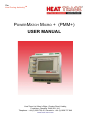
1
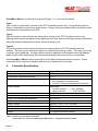
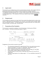
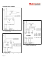
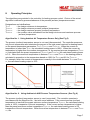
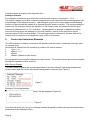
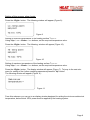
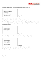
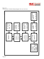
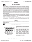
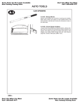
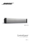
The
Heat Tracing AuthorityTM
PowerMatch Micro + (PMM+)
USER MANUAL
Heat Trace Ltd, Mere’s Edge, Chester Road, Helsby,
Frodsham, Cheshire, WA6 0DJ, U.K.
Telephone : +44 (0)1928 726 451 Facsimile : +44 (0)1928 727 846
www.heat-trace.com
Table of Contents
Page
1.
Controller & Component Parts .......................................................3
2.
Connection Methods …………….......…………………...........................3
3.
Temperature Control Methods .......................................................... 3
4. Controller Specification ............................................................4
5. Input circuit ..............................................................................................5
6. Output circuit. .........................................................................................5
7. Connection of the Controller..............................................................5
8. Operating Principles .............................................................................7
9. Control and Indication Elements .....................................................8
10. Maintenance Operation ......................................................................13
11. Marking of the Controller....................................................................13
12. Storage Conditions ..............................................................................13
13. Transportation Conditions ................................................................13
14. Junction Boxes for Sensors ..........................................................14
Page 2
1.
Controller & Component Parts
The PowerMatch Micro+ (PPM+) electronic controller is designed for temperature measurement
and control of electric heat tracing circuits. The controller provides a facility for temperature
measurement by means of one or, optionally, two measurement sensors. The output control
optimises the temperature maintenance process. The controller is straightforward, easy to operate
and maintain.
The component parts of the controller are :
•
2-channel input signal measuring unit.
•
The control unit device.
•
Power supply unit.
•
2 output relays. (1 x load and 1 x alarm).
•
Indication and control elements unit.
2.
Connection Methods
The PMM+ may be connected to provide temperature control methods Type I or II (requiring only
the Pt100 ambient sensor) or Type II (requiring both the Pt100 ambient and line sensors).
The PMM+ may be connected for circuit switching by means of:
a)
integral 16 amp, 230 volt relay (see Fig 2).
b)
external suitably rated contactor (see Fig 3).
c)
external thyristor, or solid state relay drive (see Fig 4).
3.
Temperature Control Methods - Process Temperature Accuracy
PowerMatch Micro+ can be set up to operate in a number of ways.
IEC electric trace heating standards define 3 levels of process temperature accuracy:Type I
A Type I process is one for which the temperature should be maintained above a minimum point
e.g. freeze protection of water lines. Ambient sensing control is usual.
Type II
A Type II process is one for which the temperature should be maintained within a moderate band
e.g. temperature maintenance of fuel oil lines.
Type III
A Type III process is one for which the temperature should be controlled within a narrow band e.g.
maintenance of temperature sensitive materials, such as chocolate.
Page 3
PowerMatch Micro+ can be set up to provide Types I, II, or III control methods.
Type I
Type I control is achieved by means of the PT100 ambient sensor only. Large blocks of power
may be controlled by means of a single device. Energy savings compared with a traditional on/off
air thermostat will typically be 80-90%.
Type II
Type II process control may also be achieved by means of the PT100 ambient sensor only.
Heating cables should be applied to the pipework such that heating loads approximate heat losses
when the ambient temperature is at the minimum design level.
Type III
A Type III process control may be achieved by means of both the PT100 ambient and line
sensors. The line sensor should be located on a heated line having no flow. This may need to be
a ‘dummy’ pipe (dead-leg). Heating cables should be applied to the pipework such that heating
loads closely match heat losses (this means that heating cables may need to be spiralled).
One PowerMatch Micro+ will be required for each different line temperature required. Fewer
controllers will be required compared with the use of traditional line controls.
4. Controller Specification
Temperature control range
Temperature measurement accuracy
Temperature indication accuracy
Measurement channels
Ouitput Relays
Analogue outputs (2)
Temperature sensor types * see note below
Control unit operating temperature
Enclosure protection level
Supply voltage
Control unit panel mounting
Overall dimensions
Weight
From -60ºC to +500ºC * see note below
0.5%
0.1ºC
Two channels:
- Air temperature measurement
- Surface / Process temperature (Optional)
Two relays:
- Control channel ....... 16A, 220VAC
- Alarm channel ............. 16A, 220VAC
0 - 10 V
Pt100 sensors
5ºC to 40ºC
IP20
220VAC +10%, -15%, 50-60Hz
DIN rail, 4 modules
68 wide x 85 high x 57 deep (mm)
272 grammes without sensor
* Note: Sensors are purchased seperately.
Page 4
Temperatures in excess of 180ºC require MI sensors – contact Heat Trace Limited
5. Input circuit
The controller can simultaneously process two measurement channels. Each channel performs
temperature measurement by means of a resistive temperature transducer (sensor).
The temperature sensors are type Pt100. Two wire sensors are provided. Where the sensor
is located more than 50 metres from the controller, a 3 wire sensor is required, wired as shown
in wiring diagram (Fig 1.) The resistance of the sensor extension wires must be 100 Ohms
maximum.
6. Output circuit
The controlling unit comprises an output circuit of one control relay channel and one alarm relay
channel. Both relays have a load capacity 16 A, 230 VAC, 50 Hz. Both control and alarm relays
have normally open contacts. For larger heating loads, switching should be via a suitably rated
external contactor, solid state relay, or thyristor drive.
7. Connection of the Controller
The controller is intended for installation in an electrical panel. Mounting is by DIN rail,
size: 4 modules. Connection terminals are shown in Figure 1.
Fig 1
Designation of the controller connection terminals:
•
•
•
•
•
The temperature detectors Rt1, and optionally, Rt2, are connected using two-wire sensors to terminals 1 & 3 and 5 & 7 respectively. The resistance of the
sensor connection wires must be no more than 100 Ohm.
Note - air sensor terminals 2 & 3 and surface sensor terminals 6 & 7 are linked
Power supply voltage is applied to terminals 13 and 15
Terminal contacts of control relay K1 and alarm relay K2 are 20–21 and 23–24
respectively
Analogue output signals in the voltage range 0…10 V are available at terminals 9-10 and 11-12
Page 5
Connection Wiring Diagrams
Fig 2 Wiring Diagram using Integral 16 amp, 230 volt Relay
Fig 3 Wiring Diagram suitably rated external contactor / solid state relay
Fig 4 Wiring Diagram using external thyristor drive
Page 6
8. Operating Principles
Two algorithms are provided in the controller for heating process control. Choice of the actual
algorithm is defined by presence/absence of the process (surface) temperature sensor.
Designations and clarifications:
Tair min – the design minimum air temperature.
Tsurface min – the design minimum process (surface) temperature.
Tsurface max – the design maximum process (surface) temperature.
Tsurface mid
– the medium value calculated from the design minimum and maximum process (surface) temperature.
Algorithm No. 1. Using Ambient Air Temperature Sensor Only (See Fig 5)
The process (surface) temperature sensor is not used (disconnected). The controller measures
only the air temperature and calculates the percent of the total power required for heating based
on the preset temperature parameters: Tair min; Tsurface min and Tsurface max. When the current air
temperature is lower than Tair min, the calculated heating power is 100%. When the current air
temperature is higher than the medium temperature (i.e. the required process temperature (Tsurface
mid) calculated from the preset temperatures (Tsurface min and Tsurface max) the calculated heating power
is 0 %. When the current air temperature is between Tsurface min and Tsurface mid the heating power is
calculated in proportion to the temperature based on 100% for Tair min and 0% for Tsurface mid.
For example, when the current air temperature is exactly in the middle between Tair min and Tsurface
mid, the calculated heating output is 50%.
Fig 5 Algorithm 1
Fig 6 Algorithm 2
Algorithm No. 2. Using Ambient air AND Process Temperature Sensors. (See Fig 6)
The process (surface) temperature sensor is used (connected). The controller operates in
accordance with the Algorithm No. 1 but with some additions. If the current process (surface)
temperature is less than the preset minimum surface temperature Tsurface min, the calculated heating
power is 100%, irrespective of the air temperature. If the current surface temperature is higher
than the preset maximum surface temperature Tsurface max, the calculated heating power is 0%
irrespective of the air temperature. When the surface temperature is between Tsurface min and Tsurface
max, the
Page 7
controller works according to the Algorithm No. 1.
Analogue Outputs
Two analogue outputs are provided in the controller with outputs in the range 0…10 V.
The output voltage level of both outputs is proportional to the calculated current heating power (as
a percentage of the maximum power). One analogue output can be used when smooth heating
control is to be provided by means of an external thyristor power controller. The second analogue
output may, for example, provide an indication of the heater power by means of a pointer-type
instrument calibrated for 0 to 10 V indication. Heating power (in percent) is applied according
to the time during which the heating is in the ON condition, relative to the total cycle period
corresponding to 100% heating power. This total cycle period is chosen by the user and set by
means of the controller’s menu within the range of 30 to 60 minutes.
9. Control and Indication Elements
The LED indicator is used for information I/O, 84x48 pixels resolution, comprising 6 strings, each
14 symbols long.
Information is entered into the controller by means of 4 control buttons:
1.
«Up» / «+».
2.
«Down» / «–».
3.
«Right».
4.
«Reset» (Return to main menu).
During operation the controller displays the main screen. The control buttons are used to navigate
through the controller’s other screens.
Main Screen Display
The main screen displays the current temperature of the two channels, the preset temperature
control values and the current calculated heating power in percent (see Figure 7).
Figure 7
Setting of Control parameters.
Press the «Right» button. This submenu will be displayed (Figure 8):
Figure 8
From this sub-menu you can go to a display window designed for setting the process temperature
parameters of the heating surface.
Page 8
Setting of the process alarm levels.
Press the «Right» button. The following window will appear (Figure 9):
Figure 9
Setting of minimum temperature of the heating surface Tsurface min.
Using «Up» / «+» «Down» / «-» buttons, set the required temperature value.
Press the «Right» button. The following window will appear (Figure 10):
Figure 10
Setting of maximum temperature of the heating surface Tsurface max.
Using «Up» / «+» «Down» / «-» buttons, set the required temperature value.
Press the «Right» button. The display window will appear (Figure 7). To jump to the next submenu for setting of the further operating parameters press the “Up” button.
The following window will appear (Figure 11):
Figure 11
From this submenu you can go to an display window designed for setting the minimum ambient air
temperature, below which 100% power must be applied by the heating system.
Page 9
Press the «Right» button. The following window will appear (Figure 12):
Figure 12
Setting of minimum temperature of the air Tair min.
Using «Up» / «+» «Down» / «-» buttons, set the required temperature value.
Press the «Right» button. The display window will appear (Figure 11). To jump to the next submenu for setting of the further operating parameters press the “Up” button. The following window
will appear (Figure 13):
Figure 13
Press the «Right» button. The next display window will appear (Figure 14):
Figure 14
Setting of the cycle period corresponding to 100% heater power output.
Using «Up» / «+» «Down» / «-» buttons, set the required cycle period value.
The possible range is from 30 to 60 minutes.
Page 10
Press the «Right» button. The display window will appear (Figure 13). To jump to the next submenu press the «Up» button. The display window will appear (Figure 15):
Figure 15
Press the «Right» button. The display window will appear (Figure 16):
Figure 16
The entering of a password enables the temperature parameters to be changed.
To set the password:-.
Using «Up» / «+» «Down» / «-» buttons, set the required password. Then you can opriate submenu for change/setting of the temperature parameters.
To return to the main indication screen of the controller, press the “Reset” button (Return to the
main menu).
Page 11
Page 12
Actual Temps
Ta: -10°C
Ts: 15°C
Power: 100%
Ta input: -35°C
Ts input: 25°C
temperature >
Set surface
temperature >
Set min air
time cycle >
Set power
Password >
Ts min: 10°C
Lo- temp alarm
set point
Ta min:-035°C
Set min design
air temp
30 minutes
Set power
time cycle
P/W: 110
Set password
Ts max: 10°C
Hi- temp alarm
set point
Figure 16.
The controller’s indication/ display diagram (the menu structure).
10. Maintenance Operation
•
•
•
•
Maintenance of the controller should be carried out annually. Electrical contacts must be verified, and dust/ contamination removed from the terminals of the
controller.
Verification (calibration) of the controller should be carried out by simulation of the system sensors and process requirements etc. every 2 years.
During installation and maintenance of the controller, the device must be
disconnected from the supply network.
Connection, adjustment, servicing of the controller must be performed by competent personnel.
11. Marking of the Controller
•
•
•
•
Front label with the name and the trade mark of Heat Trace Limited.
All terminals labeled with terminal number and designation.
Serial number label to the side of the enclosure.
Basic operation conditions and supply voltage label fitted to the side of the controller.
12. Storage Conditions
•
•
•
Storage temperature range: from 20°C to +60°C.
Relative air humidity (at temperature +35°C): not less than 80%.
The air in the storage room shall not contain dust, vapours of acids and alkalis, or corrosive gases.
13. Transportation Conditions
•
•
•
•
The controller must be packaged when transported.
Transportation temperature range -20°C to +60°C.
Relative air humidity (at temperature +35°C) not more than 90%.
The controller must not be transported in open conditions.
Page 13
13. Junction Boxes for Sensors
There are two sensors available for use with the PMM+ Controller, an Ambient (Air) temperature
sensor and (optionally) a Surface / Process temperature sensor. Sensors are the Pt100 type and
should be ordered seperately from the Control unit. The standard Pt100 sensors are suitable
for temperatures up to180°C. Where surface temperature sensors are required to operate at
temperatures higher than 180°C a special mineral insulated Pt100 sensor should be specified at
the time of ordering. Two wire sensors are provided as standard. Where the sensor is remotely
located more than 50 metres from the controller, a three wire sensor is required. The resistance of
the sensor wires should be 100 Ohms maximum.
Junction boxes and ancillary equipment may be sourced locally, if required. However, it is the
responsibility of the installation contractor to ensure that all equipment and components meet the
necessary local and international standards and carry the correct approvals and certification to suit
the area in which they are installed.
Fig 17 Ambient Sensor shown in JB9000 Junction Box
Fig 18 Surface Sensor with
DJB9000 (EX) Junction Box
and DESTU (Optional).
(For the surface temp sensor,
the complete unit of sensor,
DESTU & DJB9000 carries
Ex’e’ type of protection for hazardous area use.)
Page 14
Fig 19 Image showing how surface sensor
is protected on pipe by DESTU
Typical Sensor Configurations
INSTALLATION NOTES
PMM+ Controller Serial No: ............................................................
Date Purchased: ..................................................................
Date Installed: .....................................................................
Date commissioned: ............................................................
Installation Details & Comments
Page 15
The
Heat Tracing AuthorityTM
Heat Trace Ltd, Mere’s Edge, Chester Road, Helsby,
Frodsham, Cheshire, WA6 0DJ, U.K.
Telephone : +44 (0)1928 726 451 Facsimile : +44 (0)1928 727 846
www.heat-trace.com