1
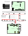
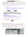
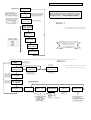
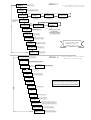
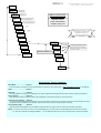
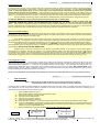
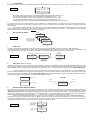
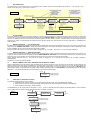
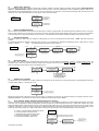
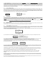
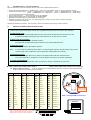
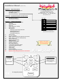
Installation Manual (version 4-2 )
Section A.
Menu Flowcharts
Fire Dynamics Ltd
3 Connaught Business Centre
Malham Rd. London SE23 1AH
PCB Layouts & Wiring Examples
“Fast-Start” instructions
The Menu Layouts
Phone. 020- 8699 8599
The Function Switches
Fax. 020- 8699 9290
Fire-dynamics.co.uk
Section B.
System description and Overview
Installation Wiring
The Detector System
Powering up the System
Section C.
1.
2.
3.
4.
5.
6.
7.
8.
9.
10.
11.
12.
13.
14.
15.
16
17
18
19.
20.
21.
22.
23.
24.
OFF
Detailed Information
View Installed Detector Responses
FireGraph
Clock & Calendar
Event Log
Walk Test (Noisy or Silent)
Service Timer
Edit Detectors
Selecting Loop & Detector Number
Selecting Detector Type
Allocating Zone LED
Entering & Editing Text
Class Change
Evacuate Facilities
Retain - Remove Last Fault Indication from Screen
FIRE - FAULT - AUX. 24v & Relay Set-up
Earth-Fault Monitor
Detector-Removed Delay
Isolate Detectors
Installer’s Text message
Disable Fault Buzzer
Auto Testing detectors
Loop Power Consumption Graph
Last-missed-response display
Reset Counter
Fault Finding
System Defaults
Customer Operating Instructions
Address-Code Settings & Detector Connections
ACCESS TO MENUS
2
spare
3
WALK-TEST
4
SILENCE ALARMS
5
VIEW POPULATION
6
CHANGE MEMORY MAP
Address-code settings
& detector connections
are on the back page
F i re P o i n t- 2
2
Fire-graph
Software Version
Time & Date
In “VIEW POPULATION”
Page Up
Last
can all be viewed by
using these buttons.
1
The 6 Function Switches on
the PCB work as shown above
1
In Standby mode
ON
Lamp
Test
Next
Page Down
3
Esc’
4
Enter
The Keypad Operation
Evacuate
LAST & NEXT lets you view the
entire installed detector
population of each loop.
PAGE UP - DOWN changes to
the other loop.
PCB Layouts and
wiring examples
LCD Socket
LCD
Contrast
Membrane
Keypad
Socket
OFF
ON
1
ACCESS TO MENUS
2
spare
3
WALK-TEST
4
SILENCE ALARMS
5
VIEW POPULATION
6
CHANGE MEMORY MAP
Ribbon
Cable
Controller PCB
1
ACCESS TO MENUS
2
spare
3
WALK-TEST
4
SILENCE ALARMS
5
VIEW
6
NEW MAP
External Communications
Keyboard
Socket
Key Switch
Evac’ ClassSwitch Change
The detectors & sounders can be fitted in any order throughout the installation wiring
CALL-POINT or INPUT UNIT
Never have a non-addressable
device such as a sounder at the
end of the wiring.
If the wires were cut here the
panel wouldn’t know because
no “address” would be missing
SOUNDER - STROBE or BELL
SMOKE or HEAT DETECTOR
“Tees” & “Spurs” are permitted
FIRE
Relay
Loop
2
- +
- +
Loop 2
Fuse 1A
Loop 1
Fuse 1A
n.o
n.c
com
Aux’ 24v
Fuse 250ma
+ -
Fault
Aux 24v
Loop
1
Ribbon
Cable
Power PCB
Set 27.4v
batt’ volts
AC Input
Fuse 2A
Battery
Fuse 2A
24v
AC
Input
To Fast-Start the Installation (& keyboard layout)
To enable the installation to be up and running quickly it isn’t necessary to enter any information for the detectors first; the system
automatically displays FIRE and FAULT plus the detector address number (as shown below); The detector type, text & zone numbers, can be
entered later when you are ready.
Before starting the installation, fill-out a “detector-location chart” first (Loop No’, Zone No’, Address No’, & Location), this will give you a
written reference to compare with at any time during the installation; before fitting any detector, set the address code and tick it off from the
chart.
Items 1 - 4 below are all you need to do to get the system up-and-running.
1.
Move “NEW MAP” switch to ON.
2.
Set the “address” switch on each detector to the required “address” and install the detector on the wiring.
3.
When all detectors are fitted and “MAP CHANGE DONE” shows on the LCD, move switch-6 to OFF.
4.
Test the Detectors. The LCD screen will show FIRE or FAULT as below.
L2
FIRE
Address
XX
L1
FAULT
Address
XX
“address” switch
number you set
on the detector
Which Loop the
detector is on
When you are ready, do the following …
5.
6
7
8.
9.
Set Time & Date
Enter “Detector Text”
Set “Detector Type” (smoke / heat detector, call-point, etc)
Set “Zone” LED for each detector
Set “Service Reminder” period, i.e. how many weeks before the system gives a
“Service Due” reminder (setting it to zero weeks turns “Service Reminder” OFF)
10. Set “Installer Text”, i.e. your Name & Phone No. on the LCD display.
MENU-1
MENU-2
“
“
“
“
MENU-3
“
“
If you get the message “INSTALLATION AND MAP MISMATCHED”, move Switch-6 (“NEW MAP”) to ON until the
LCD shows “MAP CHANGE DONE”, then turn switch-6 to OFF
Note…… The FirePoint-2 assumes a detector is fitted if you have entered a “Detector Type” code for it in MENU-2
The “detector type” codes are :-
Select “det’ type” code:
Smoke Detector SD
Heat Detector
HD
Call Point
CP
Input Unit
IU
Smoke Beam
SB
Duct Probe
DP
Unlisted
??
Not Installed
--
If you set a detector as a Call-Point for example, it expects to find a detector responding at that “address”, if the system finds no device the
display will show a fault condition for the “missing” detector.
To solve this, simply move the “NEW MAP” switch to ON and the system will automatically move any uninstalled device information into the
background, when the device is later fitted just turn “MAP CHANGE” to ON and the device will be brought on-line again.
---------------------------------------------------------------------------------------------------------------------------------------------------------
IF THE KEYBOARD SOMETIMES SEEMS A LITTLE SLOW WHEN ENTERING DATA, BE PATIENT, IT MAY BE THAT THE SYSTEM IS ALSO
CARRYING OUT IT’S POLLING, MONITORING, & “HOUSEKEEPING” TASKS AS THE SAME TIME.
F1 to F5 selects menu 1 to 5
(or use LEFT / RIGHT arrows)
Esc
F1 F2 F3 F4
Page Up & Page Down steps
you through the menu items
To delete text you are entering
use the “back-space” key
F5
Enter
Page
Up
Page
Down
Left-Right-Up-Down arrows change selection
Section A
Last & Next arrows
selects menus 1,2,3,4,5
MENU 1
PAGE DN
A star indicates a detector is
present at this address, a dash
indicates no device found.
an “i” indicates it is ISOLATED
Menu 1 – 5 Flowcharts
View Responses
14 *
PAGE DN
WARNING. When you are in the “VIEW RESPONSES”
display the system is not polling the detectors and a fire
alarm will only be shown as an “F” when you are viewing
that detector number, NO ALARMS WILL SOUND.
Gives view all of the installed
detectors, Left-Right arrows
change detector selected
PAGE DN
Left hand number = Loop No’
1st block = Det’ qty on Loop
2nd = Mis-scans first time
3rd = “ “ “ 2nd time
4th = “ “ “ 3rd time
5th = quantity of duplicates
1: 23/ 0 0 0/ 0
THE ”FIRE-GRAPH”
2: 19/ 0 0 0/
MENU 1
0 PAGE DN
14:29 11jan98
Adjust Month ?
To leave the MENUS and revert to standby :Move switch-1 to OFF at any time
PAGE DN
14:29 11feb99
Adjust Day ?
PAGE DN
14:29 12feb99
Adjust Year ?
Use LEFT - RIGHT
arrow keys to alter
Month
Day
Year
Hour
Minute
PAGE-DN will step you down
through the menu items.
ENTER will take you
sideways through the
selection
PAGE DN
14:29 12feb99
Adjust Hour ?
PAGE DN
16:29 12feb99
Adjust Minutes?
PAGE DN
MENU 2
MENU 2
Last & Next arrows
selects menus 1,2,3,4,5
PAGE DN
Press ENTER to
View Event Log
Press Esc’ to
leave the Log
Press arrow keys
to view the log
The log will display
these 5 items
Left arrow shows newest
event first, right arrow
shows oldest event first
PAGE DN
Turn key to RESET
to reset to default
service interval or
adjust using arrows
Esc’
ENTER
To leave the MENUS and revert to standby :Move switch 1 to OFF at any time
Time - date
event - loop - det’
Service Interval
56 Weeks
PAGE DN
This is the default
service interval
adjust using arrows
Next Service Due
In 3 Weeks
PRESS ESC’ AT ANY TIME
TO LEAVE “TEXT EDITING”
PAGE DN
Press ENTER to
Edit Detector Text
PAGE DN
Edit Loop
1
ENTER
Edit text for
detector : 06
ENTER
Select Loop 1 - 2
Select detector
number to edit
Edit sensor type
Smoke Detector
Chose zone LED
1, 2, 3, 4
ENTER Select detector type :
ENTER
Smoke Detector SD
Heat Detector
HD
Call Point
CP
Input Unit
IU
Smoke Beam
SB
Duct Probe
DP
alter
Unlisted
??
Not Installed
- - (Not Defined)
Left & Right Arrows
* Loop number
* Detector number
* Detector type
* Zone number
Chose which zone
lamp will be
allocated to this
detector
Text: Det’ 06 (1)
Reception Area
ENTER
ENTER
Input the
Location Text
Up & Down arrows alter
the character,
Left & Right arrows alter
the cursor position
MENU 3
Last & Next arrows
selects menus 1,2,3,4
MENU 3
To leave the MENUS and revert to standby :Move switch 1 to OFF at any time
PAGE DN
Messages WILL
be retained
Pressing left / right arrow changes
message to WON’T be retained
PAGE DN
Press ENTER to
isolate detector
Isolate detector
on Loop 1
Change Isolation
state of Det’ XX
ENTER
ENTER
PAGE DN
Enter will make all
isolated detectors
active again
Z2 Isolated 26
“Location Text”
Left-Right arrow change
Isolated to Active
Left & Right arrows
Select detector
Left & Right
arrows alter Loop
Press ENTER to
cancel isolation
ENTER
ENTER
PAGE DN
Esc’
Press ENTER to
edit Installer text
Edit TOP line :
COMPANY NAME
ENTER
ENTER
Edit LOWER line :
PHONE No’
ENTER
PAGE DN
Fault Buzzer:
enabled
Left & Right arrows change
Enabled to Disabled
Up & Down arrows alter
the character,
Left & Right arrows alter
the cursor position
PAGE DN
Earth –Fault
Monitor = ON
Left & Right arrows
change ON to OFF
PAGE DN
Remote Evacuate
Ring = Continuous
Left & Right arrows change
CONTINUOUS to PULSING
PAGE DN
Manual Ring =
Continuous
PAGE-DN will step you down
through the menu items.
ENTER will take you
sideways through the
selection
Left & Right arrows change
CONTINUOUS to PULSING
PAGE DN
Remote Evacuate
FIRE Relay = ON
Left & Right arrows
changes ON to OFF
PAGE DN
PAGE DN
Local Evacuate
FIRE Relay = ON
Left & Right arrows
change ON to OFF
MENU 4
Last & Next arrows
selects menus 1,2,3,4
MENU 4
View Responses
XX
00
To leave the MENUS and revert to standby :Move switch-1 to OFF at any time
Shows all detectors polling in “Real-Time”
with “total of missed responses” counter
*
Poll Strategy 1:
Normal Polling
Poll Strategy 2:
Single Det’ Mode
ARROW
1 =74:
2 =40:
Refer to the manual for
use of this test feature
Loop power graph
LMR Report
None
Detector response analyser
“LAST MISSED RESPONSE”
Software Version
= 3.12
Menu 4 is a series of technical displays which
have been provided to assist problem solving.
Language =044
English (UK)
Pressing PAGE DOWN will step through the selections
ROM test : Pass
RAM test : Pass
Internal diagnostics
EPROM type =
4KB
Stack size :160
Stack free : 46
Memory use analyser
Detector system
= 145028/…..
Shows which hardware
the software is set for
Restarts = 2
Reset key clears
Shows how many times the system has been
re-started since the counter was last reset.
Turning the key to RESET resets the Counter
Press ENTER to
RESET configuration
PAGE DN
Press ENTER to
ERASE Installer Text
Resets everything, except user
text, to the factory defaults
Resets Installer Text back to
“FIRE ALARM-SYSTEM NORMAL
MENU 5
To leave the MENUS and revert to standby :Move switch 1 to OFF at any time
MENU 5
PAGE DN
Is a REPEATER
Attached ? No
Left /Right arrow
alters No to Yes
PAGE DN
Is a Zone Extender
Attached ? No
Left /Right arrow
alters No to Yes
PAGE DN
Repeater Comms
Faults = 0
Shows how many times there has
been a communications fault
PAGE DN
Repeater Comms
Fails = 0
Shows how many times there has
been a communications failure
MENU 5 is the Accessory
menu which lets you
Set-up and view the operation of
Repeater Panel
Zone Led Extender
Auxiliary Relay Unit
PAGE DN
Zone Ext’ Comms
Faults = 0
DITTO
PAGE DN
Zone Ext’ Comms
Fails = 0
PAGE-DN will step you down
through the menu items.
ENTER will take you
sideways through the
selection
DITTO
PAGE DN
Zone Rept’ Comms
Faults = 0
PAGE DN
Zone Rept’ Comms
Fails = 0
PAGE DN
Press Enter for
AUX’ Relay Test
ENTER
PAGE DN
AUXILIARY FAULT
Relay = Inactive
PAGE DN
AUXILIARY FIRE
Relay = Inactive
When you leave this test mode the relays
always return to their “relaxed” mode (unless
that condition is present)
PAGE DN
AUX Relay Comms’
Fails = 0
PAGE DN
PAGE DN
Left /Right arrow alters INACTIVE to ACTIVE
and causes that particular relay to operate.
PAGE DN
AUX Relay Comms’
Faults = 0
External IIC Bus
Jams = 0
PRESSING ESC’ AT ANY TIME TAKES
YOU BACK TO THE MAIN MENU
CROSSOVER
Relay = Inactive
PAGE DN
EVACUATE
Relay = Inactive
PAGE DN
Relay ZONE 1
= Inactive
PAGE DN
Relay ZONE 10
= Inactive
PAGE DN
The Engineers Function Switches
Menu Mode……………………Switch 1
In the ON position, this allows access to the five Menus by pressing Last / Next Arrows, or ESC’ plus buttons 1,2,3,4,5 on the keypad.
Spare…………………………..Switch 2
Walk-Test…………………….. Switch 3
In the ON position, the system is non-latching; so an alarm condition will reset itself when the alarm cause is cleared, see Section 5.
Silence Alarms……………….Switch 4
When this switch is ON, any alarm condition will be displayed at the control panel but no alarms will sound.
View Detector Population…..Switch 5
To view the entire installed detector population move Function Switch 5 to ON and use the four arrow keys to scroll through both Loops
(A detector cannot be viewed until it has been entered in the memory map by moving switch-6 to ON first)
Change Memory Map………..Switch 6
When this switch is ON detectors may be added and removed from the system, when it is OFF the information is locked in.
NOTE.. If you are in any part of any menu, you can immediately go to any other menu by pressing ESC’ plus the other menu number,
e.g. Esc’ and 4 will take you straight to MENU-4; you can leave the menus at any time by moving switch-1 to the OFF position.
Section B
Detailed System Description & Overview
Installation Wiring
In these instructions the term “Loop” is used to mean the 2-core fireproof cable you install throughout the building to connect the detectors
and sounders to the FirePoint-2 control panel, in practice there is no need to actually form the wiring in a Loop. If using Pirelli FP200,
Firetuf, or similar type flexible cables, all of the screen (drain) wires should be firmly connected at all joints to form a continuous
earthed shield to the whole wiring installation. When upgrading an old system, if there isn’t earth continuity on the existing cables, use
with caution. Use separate 2-core cables for each loop throughout the installation rather than a single 4 core containing both loops in case this
results in cross-channel interference; The FirePoint - 2 is will accept “spurs” and “tees” off the wiring and doesn’t need “end-of-line resistors”.
The term “Detector” will mean any smoke or heat detector, addressable base, call-point, smoke-beam, duct-probe or input unit.
To conform to BS5839 each Loop should have at least one alarm sounder and one detector fitted.
NEVER USE A MEGGER OR OTHER HIGH VOLTAGE TESTER ON THE WIRING IF THE CONTROL PANEL OR DETECTORS ARE
CONNECTED; DAMAGE WILL RESULT AND THE WARRANTY WILL BE VOID. Only use an AVO 8 or similar type of low voltage
meter.
Static electricity is extremely hazardous to electronics, walking on carpet containing nylon or other man made fibre generates large
amounts of static electricity which discharges into the electronics when touched causing instant damage. If the detectors or control panel are
fitted you should always earth yourself before touching any of the wiring conductors, termination screws or metal parts.
Detector system description
The FirePoint-2 is a 2-loop addressable control panel with a capacity of 64 detectors on each loop, all detectors on the loops are
polled within a 3-second period and the loops are polled in parallel to stay within this time frame. When a detector is polled or interrogated by
the control panel its LED will give a short flash in reply.
All the detectors send their own unique “address code” back to the control panel which then compares it to a similar “map” in its
non-volatile memory. The FirePoint-2 constantly compares those devices responding on the wiring with its memory map and if any detector
should become missing this will be recognised and displayed on the LCD screen. Even when the system is de-powered the map is retained.
If you add or remove any detectors from the installation, the “NEW MAP” switch should be moved to the ON position to allow the
new configuration map to be stored in the memory, if a detector is added to the system without the memory map switch being turned ON the
LCD will display “INSTALLATION AND MAP MISMATCHED”.
Address 0 (zero) on each loop is reserved as a “non-latching, pulsing-alarm” address, so, for example, if your fire alarm system is
interconnected to a Landlord’s “staircase only” system, or to an adjacent building’s system, if the other control panel sends a FIRE signal to
your detector set to address 0 it will tell the FirePoint-2 to pulse the alarms ON and OFF every few seconds and display “FIRE” and the
Location Text, when the other system is reset the FirePoint-2 will auto-reset after a few sec’s (the information will still be recorded in the Log).
When address 0 is triggered, the Aux.’ fire relay will NOT change-over to prevent the two systems from “nesting”, or “locking in a loop”.
Powering up the system
When the FirePoint - 2 control panel is powered up the mains supply should be connected first, whereon the LED’s on the front
panel will cascade and the buzzer sound while the internal systems initialise, this takes about 10 seconds after which the display may show
“MICROPROCESSOR RESTART = 1”; turning the key to RESET clears this from the display. After connecting the battery and the Loop
wiring move the “NEW MAP” switch on the PCB to the ON position and after several seconds the message “MAP CHANGE DONE” will be
displayed together with the quantity of detectors on each loop; moving the switch back to the OFF position will show the system scrolling
through the detectors and locking the information into memory.
Never connect the batteries the wrong way round; damage will result which is factory detectable and not covered by the warranty.
Section C
1.
Detailed System Information
VIEW RESPONSES
NOTE… While using this facility the detectors are not being polled and are inoperative,
the EVACUATE switch on the front of the control panel is still fully operational.
This display shows if a detector is being registered at the address number on the left of the screen, by scrolling through all 64 addresses you can
view all detectors on both Loops. When a detector is selected on the screen, the LED on the actual detector will remain lit enabling you to
precisely determine the address number a detector is set to.
“*”
“-“
“F“
“O“
“S“
“i”
“M”
“N”
(star) indicates a detector is present.
(dash) means no detector is being seen at that address number.
means that the detector is in FIRE condition.
means the Loop is OPEN CIRCUIT
means the Loop is SHORT CIRCUIT
means that that detector is ISOLATED.
means MULTIPLE responses i.e. you have more than one detector on a loop with the same address number setting.
means NO RESPONSE from that detector, possibly caused by the detector being removed from it’s base (if the memory map
expects to see a detector responding from that address location and doesn’t get it it will assume that the detector is wrongly
missing and give a NO RESPONSE signal).
“ ? “ means that the detector is NOT YET DEFINED and will not give FIRE OR FAULT signals.
MENU 1
1
View Responses
20
* -
2
View Responses
21
M
i
*
In example 1 above, loop-1 has detector number 20 installed and loop-2 has nothing at address 20; In example 2, detector 21 on Loop-1 has
another detector with the same number on the loop (Multiple), and detector 21 on loop-2 is isolated ( i ).
2.
The FIREGRAPH
This facility shows the “condition” of the signals coming back from the detectors on each loop; the top line is Loop 1, the bottom line is Loop 2.
MENU 1
1: 37/ 2 1 0/
1
2: 23/ 0 0 0/
0
The number on the left of the screen is the total number of detectors being seen on each loop.
st
The next block indicates the number of mis-responses from the detectors on the 1 scan.
nd
The next block indicates the number of mis-responses from the detectors on the 2 scan.
rd
The next block indicates the number of mis-responses from the detectors on the 3 scan.
The right hand block shows the number of duplicated addresses or un-mapped detectors on each loop.
In the example above, Loop 1 has 37 detectors, with 1 duplicate or un-mapped detector; the first scan block shows that 2 detectors misresponded on the first cycle, one detector on the second scan, and non on the third (a FAULT condition occurs after 4 consecutive bad scans
from a detector)
An occasional number in the first or second scan box is not unusual and does not necessarily indicate the presence of a fault, whilst
multiple numbers in the second and third-scan boxes should be treated as early warning signs of a FAULT. In Non-Menu mode, the FireGraph
can be viewed instantly by pressing button number 1 on the Keypad.
3.
SET CLOCK & CALENDAR
PAGE DN
Adjust Month
Adjust Day
MENU 1
Adjust Year
PAGE DN will step through
the TIME & DATE settings
Left - Right arrows adjust
Adjust Hours
Adjust Minutes
PAGE DN
4.
EVENT LOG
The event log will retain approximately the last 100 events in its memory; the log will NOT record Class-Change or Walk-Test events.
The log will record the Time, Date, Type of event, Loop number and Detector number; every event in the log will have first been displayed on the
LCD screen when it occurred, when the log fills up the oldest event will be discarded so that the new event can be recorded.
Press Esc’ to
leave the Log
PAGE DN
MENU 2
Press ENTER to
view event log
Use left-right arrow
keys to view log
ENTER
PAGE DN
ESC’
Left arrow shows
newest event first,
Right arrow shows
oldest event first
Time….date
event..loop..det’
The log will display
these 5 items
5.
WALK TEST. (NOISY or SILENT)
This facility allows the system to auto-reset from an alarm condition, so that when a detector is set into FIRE the alarms will reset after 2 seconds;
when the alarm condition is removed the control panel will automatically return to the standby mode, this facility allows one-man testing of the
entire installation without having to manually reset the control panel each time. In Walk-Test mode the display will show “NOISY WALK-TEST”.
In certain situations you may wish to turn the alarm sounders off during walk-test (e.g. in a hospital, office, etc, when multiple alarm
sounding would be undesirable), to do this move Function Switch 4 to ON, the sounders will be silenced until switch-4 is moved back to its OFF
position, during this time the display will show “SILENT WALK-TEST”; when a detector is triggered during noisy and silent-walk-test it’s LED will
pulse brightly to give a visual indication the control panel has received the signal.
Noisy Walk-Test
SHOWS ALARM
IS A WALK-TEST
SWITCH 3 ON
ZONE No’
DET’ No’
LOOP No’
Silent Walk-Test
LOCATION
z2
L1
SWITCH 3 & 4 ON
TEST SD36
Wages Office
6.
SERVICE TIMER & SERVICE INTERVAL
You can set the Service Timer to remind the system user when a service of the fire alarm system is due; when the service is due the FirePoint-2
will flash the fault LED’s continuously and sound the internal buzzer once every 5 minutes, the display will also alternate between the message
“Maintenance Service Due” and the “Installer message” (which may be the company name and phone number). The “Service Reminder” can be
turned OFF by setting the time to zero hours, or up to 156 weeks in advance, you can also view how many weeks before the next “Service Due”
reminder by seeing how far the “Next Service Due In … “ has remaining……the default service interval is 56 weeks.
When a service has been carried out, the Service Timer can be reset to it’s pre-set period by going to “Next Service Due In … “
message and turning the control panel key-switch to RESET, whereon the display will reset to the default interval you have set and show how
many weeks to the next reminder, or you can set to however many hours, days, or weeks you require manually via the keypad. The “Service Due”
message will disappear from the screen whenever a FIRE or FAULT message is present.
PAGE DN
MENU 2
Turn key to RESET
to reset to default
service interval
Next service due
in 4 days
PAGE DN
This is the default
interval
Service interval
56 weeks
PAGE DN
7.
EDIT DETECTORS
The “detector text” is the information shown on the display when a FIRE or FAULT occurs; the display will also show :- Loop number (1 or 2);
Device number (det’ 0-63); Device Type; Zone No’.
Up & Down arrows alter
the character,
Left & Right arrows alter
the cursor position
Left & Right Arrows alter
Loop number
Detector number
Detector type
Zone number
MENU 2
PRESS ESC’ AT ANY TIME
TO LEAVE “TEXT EDITING”
PAGE DN
Press ENTER to
edit detector text
PAGE DN
Edit Loop 1
ENTER
Select Loop 1or 2
Edit text for
detector : 06
ENTER
*
Edit sensor type
Smoke Detector
ENTER
Press ENTER to
cancel Isolation
PAGE DN
Text: Det’ 06 (1)
Reception Office
ENTER
Chose which of the
4 zone LED’s will
be allocated to this
detector
If the LCD shows “SOME ZONE LAMPS
AREN’T AVAILABLE” you have set a
zone LED to an unavailable zone number
ENTER
Select det’ type :
Smoke Detector
Heat Detector
Call Point
Input Unit
Smoke Beam
Duct Probe
Unlisted Type
Not Installed
Select detector
number to edit….
A star (*) or cross (X)
beside the number
shows that a device is
responding at that
address location
Choose zone led
1,2,3,4
SD
HD
CP
IU
SB
DP
??
--
ENTER
When a detector is selected as “Not Installed” it
will behave the same as an isolated detector
except that the display will show a FAULT
8.
CLASS CHANGE
This facility allows the alarms to be sounded remotely by closing a pair of normally-open contacts connected to these terminals, the alarms will
sound for as long as the closed-circuit lasts and the display will show “MANUAL RING”; this will NOT be recorded in the Log and no red fire lamp
will come on. Removing the short-circuit will return the control panel to the silent standby condition. A suitable switch for class-change would be a
single-pole n/o switch. In Class-Change the auxiliary fire relay will NOT change-over. Class-change can be set to “PULSING” or “CONTINUOUS”
mode in menu 2
9.
MANUAL EVACUATE 1 (LOCAL EVACUATE)
The alarms can be triggered immediately by turning the key to RESET and pressing the EVACUATE button on the front of the control panel; the
display will show “MANUAL EVACUATE” and the alarms will sound and the zone lamps will cascade until the key is turned to SILENCE. Turning
the key to RESET will return the control panel to the standby condition.
During “Evacuate” the auxiliary fire relay can be made to change-over or, not operate - see section 11 on the next page or MENU-3
MANUAL EVACUATE 2 (REMOTE EVACUATE)
The alarms can be triggered immediately by closing a pair of normally-open contacts connected to these terminals, the alarms will sound for as
long as the closed circuit lasts and the display will show “REMOTE MANUAL EVACUATE”; this event will be recorded in the Log and all red fire
lamps will come on and cascade, removing the closed-circuit will return the control panel to the standby condition.
During “Remote Evacuate” the Aux’ fire relay can be made to change-over, or not operate, and the alarms can be made PULSING or
CONTINUOUS.
See section 11 on the next page or MENU-3.
10.
RETAIN / REMOVE LAST FAULT INDICATION ON THE DISPLAY SCREEN
With an intermittent fault it can be useful to retain the details of the last fault occurrence on the LCD screen so that the user can accurately tell you
what the fault was, but under some circumstances it can lead a user to think there is a fault when there isn’t, e.g. when the mains supply has
failed and come back on the display would still show “Main Electricity Supply Failed”, so it may be prudent to set the system to RETAIN the last
fault indication during a trial period when the system is first installed, and set the system to NOT RETAIN the fault indication after this trial period;
Remember…. the fault will be retained in the Log anyway so it can always be viewed later.
PAGE DN
MENU 3
Messages WILL
be retained
Left / Right arrow changes
to “WON’T” be retained
PAGE DN
11.
FIRE, FAULT & AUXILIARY OUTPUTS
The outputs from the FirePoint-2 are as follows:1. FIRE RELAY with volt-free change-over contacts rated 24volts @ 2 amps.. NOT FOR MAINS VOLTAGES.
2. FAULT driver transistor for switching 24volts @ 70mA.(Note! O/p is normally energised in standby mode (BS5839)
3. 24v dc Auxiliary power output (fused at 250mA).
The FIRE RELAY can be programmed to changeover, or not, in “Local” or “Remote” Evacuate conditions by following MENU 3, also the alarms
can be made pulsing or continuous when “Remote Evacuate” is operated, as follows :PAGE DN
MENU 3
Press Enter to
edit Installer Text
ENTER
Edit TOP Line :
COMPANY NAME
PAGE DN
Remote Evacuate
Ring = Continuous
Left & Right arrows change
CONTINUOUS to PULSING
PAGE DN
Remote Evacuate
FIRE Relay = ON
Left & Right arrows
changes ON to OFF
PAGE DN
Local Evacuate
FIRE Relay = ON
PAGE DN
Left & Right arrows
change ON to OFF
ENTER
Edit BOTTOM Line
PHONE No’
ENTER
12.
EARTH FAULT MONITOR
If a low resistance should occur between system earth and either negative or positive voltage, the display will show either “NEGATIVE EARTH
FAULT” or POSITIVE EARTH FAULT” and the internal buzzer will sound. The Earth Fault Monitor can be disabled by going to Menu-3 and
setting EARTH-FAULT MONITOR option to OFF, you can turn it back ON in the same way. If the earth-fault is existing when you want to turn the
monitor off; Turn it off as described above, then de-power, and re-power the system.
PAGE DN
MENU 3
Left & Right arrows
changes ENABLED
TO DISABLED
Fault Buzzer is
Enabled
PAGE DN
Earth-Fault
Monitor is ON
Left & Right arrows
change ON to OFF
PAGE DN
13.
DETECTOR REMOVED DELAY
When a smoke or heat detector is removed from its base there is a delay of approximately 12 seconds before the condition is shown on the LCD
screen so that a detector can, for example, be removed for cleaning, or blowing out after smoke testing without a FAULT showing, but if a detector
is left out longer than 12 seconds the display will show “FAULT” and alternate with the “default message” (installers name & phone number).
14.
ISOLATE DETECTORS
To isolate a detector so that it does not respond to FIRE signals, go to menu 3 and follow the flow-chart below ; NOTE. Call-Points cannot be
isolated.
To de-isolate INDIVIDUAL detectors repeat the same process, or to de-isolate ALL detectors simultaneously press “Press Enter to Cancel
Isolation” in Menu-3.
Note !…. An Isolated detector will still report fault conditions
MENU 3
PAGE DN
Press ENTER to
isolate detector
ENTER
PAGE DN
Enter will make all isolated
detectors active again
Isolate Detector
on Loop 1
ENTER
Left & Right
arrows alter Loop
Change isolation
state of det’ XX
ENTER
Select the detector
to be Isolated
Z2 Isolated
26
ENTER
”Location Text”
The Arrow Key Changes
Isolated to Active
Press ENTER to
cancel isolation
PAGE DN
15.
INSTALLERS TEXT
The “Installers Text” message is the information that will be shown on the LCD display during standby, a FAULT, or when a service is due, the
message can be 2 lines of 16 characters and will usually be the company name on line 1, and the telephone number on line 2, although you can
enter any message you wish with a limit of 16 characters per line.
PAGE DN
MENU 3
Press ENTER to edit
Installers Text
ENTER
Edit TOP Line
THE COMPANY NAME
PAGE DN
ENTER
Edit LOWER Line
THE PHONE No’
ENTER
Up & Down arrows alter
the character,
Left & Right arrows alter
the cursor position
16.
DISABLE FAULT BUZZER
The fault buzzer can be disabled by an option in Menu-3, the buzzer will only be muted for non-critical system faults, it will still operate when there
is a Main Supply, Battery, or Auxiliary 24v fault
MENU 3
Press ENTER to edit
Installers Text
PAGE DN
Fault Buzzer is
ENABLED
LEFT – RIGHT arrows change
ENABLED to DISABLED
NOTE. When the buzzer is silenced and you exit menu mode, or whenever you exit from any engineer functions, the display will show “FAULT
BUZZER DISABLED” as a reminder, the screen can be cleared by turning the key-switch to RESET.
17.
AUTO TESTING / SINGLE TESTING OF DETECTORS (Polling Strategy)
This is a “real-time” view of the detectors being polled and responding. In normal polling all detectors are interrogated approximately once every
3-seconds; and in single detector polling approximately 25 times-per-second, and should respond each time. If a detector’s response isn’t within
certain parameters at the control panel the number on the right will increase with each cycle, this number can be reset to zero by turning the key
to RESET. This feature is purely for analysis purposes by experienced engineers and should be regarded solely as an aid to fault finding, a high
number by itself means nothing, but a high number within a short period may indicate a fault, caused possibly by one of the following :a.
b.
c.
d.
e.
A faulty, or off-specification addressable device
A bad connection on the loop wiring
Interference being induced into the cable
High cable capacitance or resistance
Low resistance between cable cores
MENU 4
View Responses
XX
00
- *
Shows all detectors polling in “Real-Time”
with “total of missed responses” counter
PAGE DN
Poll Strategy = 1
Normal Polling
PAGE DN
Continued on next page
Polling Strategy = 2
Single Det’ Mode
Left - Right arrows
change the test mode
then PAGE-UP
The TEST STRATEGY lets you change the display from auto-polling ALL detectors, to polling only a SINGLE selected detector; in this way every
individual detector installed can be examined to locate the source of mis-responses; but again, these features are for the aid of knowledgeable
engineer’s to assist in analysing and locating faults and should only be used in conjunction with other information gathered. NOTE when you are
in single detector mode the fire alarm system is only polling the actual detector you see on the LCD and all other detectors are inoperative, before
leaving menu 4 you should change the setting back to AUTO TESTING. The EVACUATE switch on the front of the control panel will still be
fully operational during “Single Detector Polling”.
18.
LOOP “POWER“ GRAPH
This display shows in numeric and graphical form the “power” driven to each loop, these graphs are not intended to show true values in milliamps, volts, watts or any other commodity, but should be considered only as a visual-aid for fault finding, for example if you had 30 detectors on
each loop you would expect to see a similar size graph for each loop, but if one loop showed a significantly higher number it could mean, in MICC
for example, that there could be damp in the cable causing a low resistance across the cores; this display should only be used to assist in
analysing and locating faults and then only in conjunction with other information gathered.
PAGE DN
1 =74:
2 =35:
MENU 4
Loop “Power” Grap[h
PAGE DN
19.
LMR REPORT
This display shows the “LAST MISSED RESPONSE” from a detector and can be used in tracing intermittent faults on the installation; this feature
will only retain the details of the very last detector to give a single mis-response, this mis-response may not be in the log because a detector must
mis-respond 4 consecutive times before the log records it as a fault, the number on the top line shows the total quantity of mis-responses from all
detectors that have occurred since the counter was last reset to zero, resetting to zero is done by turning the key to RESET.
This display should only be used by knowledgeable engineers to assist in analysing and locating faults and then only in conjunction with other
information gathered, large numbers on the “LMR Report” do not necessarily mean the system is faulty.
20.
RESET COUNTER
This display shows how many times the system has been re-initialised (i.e. de-powered and re-started) since the counter was last reset, turning
the key to RESET resets the counter to zero, the Event Log records every time the system is re-initialised.
21.
FAULT FINDING and general information
A common mistake which occurs is when you fit a detector onto a loop and accidentally program it onto the other loop, you will get a message
similar to below, where detector 20 should be on Loop-1 but is showing “No Response”, and the LCD shows one present on Loop-2 when there
shouldn’t be any. Re-programming detector 20 onto Loop-2 instead of Loop-1 will solve the problem.
There is no need to de-program detector 20 from Loop-1 if you don’t want to - simply by moving the “Map Change” switch to ON the control panel
will “hide” this wrong information from the display.
View Responses
20 N
*
If you add a detector to the installation that has the same address number as an existing detector you will get a message similar to below :Zx MULTI ??17
Lx “Location Text”
“Zx” is the zone number
??17 is the duplicated “address” No’
“Lx” is the Loop No’
“Location Text” is the text you have entered
If you connect an extra detector to the installation, the system will not “see” the new detector until it is in the memory-map, and as such it will
not give FIRE or FAULT indications. The display will show the warning - “MAP & INSTALLATION MISSMATCHED”.
To add the detector into the memory map, move the MAP CHANGE switch (Switch-6) to the ON position and after a few seconds the
message “MAP CHANGE DONE” will appear with the new quantity of detectors on each Loop, move the switch back to the OFF position and
the new memory map is saved.
Wait…..checking
L1 : 37
L2 : 44
Map Change Done
L1 : 38
L2 : 44
If you were to mistakenly put the positive or negative wire of loop-1 into Loop-2 terminals, and vice versa; the led on each detector would still
flash but they wouldn’t go into FIRE condition, also you may find that on MAP CHANGE there could be the wrong quantity of detectors shown,
uncrossing the wires and putting them back in the correct terminals will resolve the problem.
A flashing LED on a detector doesn’t mean the detectors in the memory, the map-change switch must have been put to the ON position first.
To find a missing detector :- go to menu-1 and use the “VIEW RESPONSES” display, use the left / right arrows to go through the numbers on
each loop, all of the installed detectors will have a “star” symbol to indicate YES, or a “dash” for NO (see section C, part 1).
To find a “MULTI” detector:- Usually it’s quickest to look for a “missing” detector that should be there; go to menu-1 and use the “VIEW RESPONSES” display. The “missing” detector has probably been set to the same number as another detector causing a “MULTIPLE”
message.
To check what “address” number a detector is set at, go to VIEW RESPONSES and use the left / right arrows to step through all 64 numbers
individually; when you reach the number that the detector is set to it’s LED will stay on, in this way you can confirm the correct address setting
of every installed detector.
If you get the message “SHORT CIRCUIT ON LOOP 1 (or 2) disconnect the loop wiring immediately and trace and remove the short circuit, a
short circuit on the loops will eventually cause components on the PCB to heat.
22.
SYSTEM DEFAULTS (FACTORY SETTINGS)
When the FirePoint-2 control panel arrives it will have a set of factory default settings which are :* All “Detector text” will be displayed as “ADDRESS XX”, (where “XX” is the address number you set on the detector switches).
* The Zone LED allocation will be :- (LOOP 1, ADDRESSES 0-31 = ZONE LED 1) (LOOP 1, ADDRESSES 32-63 = ZONE LED 2)
(LOOP 2, ADDRESSES 0-32 = ZONE LED 3) (LOOP 2, ADDRESSES 33-63 = ZONE LED 4)
* The LCD will NOT retain the last fault indication.
* Service Timer will be ON......... Service Interval will be set to 56 WEEKS
* Default Installer Message will be “FIRE ALARM - SYSTEM NORMAL”.
* REMOTE EVACUATE ringing will be CONTINUOUS (not pulsing)
* REMOTE EVACUATE relay will be ON ( the relay contacts WILL change over when remote evacuate is operated )
* LOCAL EVACUATE relay will be ON
“
“
“
“
“
Resetting the defaults will not affect :- The Log entries; Location Text; “Detector type” settings; Clock & Calendar.
23.
EXAMPLE CUSTOMER OPERATING INSTRUCTIONS
If the fire alarm system is operating normally the only lights illuminated will be the “SUPPLY ON” indication.
If a FIRE should occur
The main alarm sounders will operate and the control panel will show the exact location of the fire.
Evacuate the building avoiding the area where the fire is. Do not Shout, Run, or Panic.
To Silence the alarm sounders
Turn the key-switch to the “SILENCE” position.
(the main alarm sounders will stop and a buzzer in the control panel will sound)
To Reset the system
Turn the key-switch to the “RESET” position.
Note !.
If a smoke detector still has smoke inside it or a call-point glass is broken, the alarm will go into its alarm
condition again; either ventilate the area or replace the call-point glass as necessary.
If a Fault should occur
The Yellow fault lights will come on and the LCD display window will show what the fault is.
Turn control panel key to “SILENCE” to mute the buzzer and contact your service organisation.
To sound an EVACUATION
Press and hold the EVACUATE button and firmly turn the key to RESET at the same time.
Tear off
24. Detector “Address” settings……..to set the “address code” on a detector Base, Call-Point, or Input Unit, set the switches shown
to ON, all other switches should be in the OFF position.
Detector
Address No’
Set these
switches ON
Detector
Address No’
Set these
switches ON
Detector
Address No’
Set these
switches ON
Detector
Address No’
Set these
switches ON
1
1
17
5-1
33
6-1
49
6-5-1
2
2
18
5-2
34
6-2
50
6-5-2
3
2-1
19
5-2-1
35
6-2-1
51
6-5-2-1
4
3
20
5-3
36
6-3
52
6-5-3
5
3-1
21
5-3-1
37
6-3-1
53
6-5-3-1
6
3-2
22
5-3-2
38
6-3-2
54
6-5-3-2
7
3-2-1
23
5-3-2-1
39
6-3-2-1
55
6-5-3-2-1
8
4
24
5-4
40
6-4
56
6-5-4
9
4-1
25
5-4-1
41
6-4-1
57
6-5-4-1
10
4-2
26
5-4-2
42
6-4-2
58
6-5-4-2
11
4-2-1
27
5-4-2-1
43
6-4-2-1
59
6-5-4-2-1
12
4-3
28
5-4-3
44
6-4-3
60
6-5-4-3
13
4-3-1
29
5-4-3-1
45
6-4-3-1
61
6-5-4-3-1
14
4-3-2
30
5-4-3-2
46
6-4-3-2
62
6-5-4-3-2
15
4-3-2-1
31
5-4-3-2-1
47
6-4-3-2-1
63
6-5-4-3-2-1
16
5
32
6
48
6-5
00
All OFF
IMPORTANT NOTE !!
Ensure the detector base is mounted on a very flat
surface so that the electronics are not subject to
twisting when the mounting screws are tightened
ON
OFF
1
6
1
6
Negative
IN & OUT
4
5
Positive
IN & OUT
MAKE NO
CONNECTIONS
Unit will be damaged
Detector Base
NOTE. Connect base ONLY as shown here.
Call-Point
ON
OFF
1
1
6