1
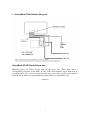
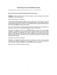
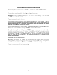
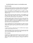
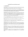
SmartBank II owners/installation manual
1 - DESCRIPTION
SMARTBANK II is an auto-battery combine controller that monitors two battery banks
and by making accurate measurements decides when to parallel them to allow
simultaneous charging and when to separate them to prevent cross-discharging.
Unlike conventional split charge systems using diodes or relays SMARTBANK II is not
affected by where the charge is coming from, nor does it have to be separately controlled
by alternator signals, manual switches etc. There is nothing for you to forget. Neither
does it suffer from the voltage drop problems of split charge diodes.
SMARTBANK II automatically controls charging of 2 battery banks no matter which
battery bank is being charged. Whether it is an alternator, solar panel, wind generator or
AC powered charger SMARTBANK II will take care of it automatically. You make sure
your charge source is connected to one battery bank. SMARTBANK II will take care of
the other one, totally automatically. No more flat engine batteries because you forgot to
switch the battery selector over. No more uncharged house bank.
Not only is SMARTBANK II better than a standard split charge relay or diode set up but
it's actually simpler and quicker to install. In most instances 3 wires is all you need !
Should a fault occur in your charge source producing an over voltage situation
SMARTBANK II will disconnect the other battery bank to prevent damage to it.
An optional remote panel is available which connects to SMARTBANK II simply by
plugging in an RJ11 type cable (supplied with the remote).
SMARTBANK II has been designed and built using ultra low power semi-conductors
and ultra low power design techniques which results in a standby current that is so low,
no ON/OFF switch is required. Therefore you can never forget to switch SMARTBANK
II on because you never need to switch it off. Standby power consumption is less than 0.2
Ah per week.
SMARTBANK II also uses switch mode technology to control the relay coil and thus
keep the power consumption to an absolute minimum whilst in the connected mode
(typically using less than half the power of an equivalent standard split charge relay).
This is vital when a small charge source such a solar panel is being relied upon to
maintain batteries.
SMARTBANK II is available in 3 sizes. For installations with up to 80, 125 or 200 amp
charging sources. SMARTBANK II/80, SMARTBANK II/125 and SMARTBANK
II/200
1
SMARTBANK II is also available as an OEM unit which consists of just the main
control unit, without the relay or mounting plate. Known as the SMARTBANK II OEM
this unit allows installers to use their own preferred relays (of almost any type and size)
but still benefit from all the advantages of SMARTBANK II. A simple 5 wire connection
is required between the SMARTBANK II OEM and the relay and GND. The
SMARTBANK II OEM can be mounted anywhere. Installers will notice the vastly
reduced current consumption and much cooler running temperature of their usual relay
choice when using this option. SMARTBANK II OEM is identical in functions and
features to the standard SMARTBANK II and can be used with the optional remote
panel.
Additional features only available with the optional remote panel
LED status indicators showing STANDBY mode, CONNECTED mode, HI VOLTAGE
shut down and FAULT.
Manual override switch to manually connect the relay for emergency engine starting.
How SMARTBANK II works.
SMARTBANK II continually monitors both battery banks. Should either battery status
indicate that a charge source is available SMARTBANK II will connect the batteries
together via the relay ensuring that both battery banks are charged. This will not happen
immediately. There will be a short delay while SMARTBANK II verifies that the charge
source is valid. Once the charge source is removed (or a very heavy load is connected that
risks flattening all the batteries in the event that the charge source cannot keep up with
the current requirements) it will disconnect the banks ensuring that your house bank loads
do not discharge the engine battery. All settings are user adjustable.
--ooOoo--
2
2 - INSTALLATION
Installation could not be simpler.
WARNING Incorrect wiring of this unit may cause serious damage to the electronic
circuit and/or relay that will not be covered by the warranty.
It is recommended that the main control unit be sited as close to the batteries as possible.
Not only does this make the cable installation easier but it also reduces the losses that
would otherwise occur with running high battery charge currents through long battery
cables.
WARNING The usual precautions regarding relays in proximity to possibly explosive
battery gasses should be taken. If in doubt consult a qualified marine/auto electrician.
As all control and indication is by way of the optional remote panel, the siting of the main
control unit can be made purely on a “safety and ease of installation basis”.
WARNING This unit contains sensitive electronic circuitry and the usual precautions
should be taken regarding water, dirt and oil ingress etc.
Refer to the diagram for your particular unit. If installing a SMARTBANK II OEM
referring to either of the three diagrams will show the required wiring system.
WARNING. Incorrect wiring to any of the terminals (and in particular the relay coil
terminals, C1 and C2) may cause serious, irrepairable damage to the unit that will not be
covered by the warranty.
It is recommended that 1mm2 cabling be used for the connections to the main terminal
block. If the GND connection (or in the case of the OEM unit the connections between
B1, B2, and the relay terminals) needs to be over 3 metres for any reason then it is
recommended that this cable be increased to 2mm2. This is purely to increase the
accuracy of the voltage measurements.
The cabling from the batteries to the main relay terminals cannot be specified in this
manual as it depends upon the installation and cable lengths etc. As a rough guide you
should use cable that will have a maximum voltage drop of 0.1 volts at the maximum
charge rate in your installation. Obviously this depends upon the cable length. If in doubt
consult a qualified marine/auto electrician.
In any event a cable capable of handling the maximum charge capability of the
installation MUST be used. Your cable supplier will be able to advise you on this point.
Failure to adhere to these instructions could result in overheating of the battery cables.
--ooOoo--
3
3 - SmartBank II Installation Diagram
SmartBank II OEM installation note
Mounting holes are drilled in the back of the main case. These holes have a
corresponding clearance on the PCB. Screws with a head diameter up to 8mm may be
used with safety. Use of screws larger than this may cause short circuits on the back of
the PCB. These holes are countersunk and countersunk screws should be used.
--ooOoo--
4
4 - SET UP PROCEDURE
There are three methods of setting the unit up. Choose whichever of the following suits
you, your equipment and expertise best:Decide on your voltage set points. If you are unsure of these refer to section 5 for
standard set up guidelines. Professional installers may have their own preferred settings
depending upon the installation.
STANDARD SET UP
NOTE. If setting up an installation with the remote panel ensure that the switch is in the
up position. Yellow LED will be OFF..
1.
2.
3.
4.
5.
Turn VR1 and VR3 fully clockwise. Turn VR2 fully anti-clockwise. If using a
remote panel the Green LED will be pulsing. Red LED off. Yellow LED off.
Run the batteries down a bit. Switch on a charge source (engine alternator, AC
powered charger, wind generator, whatever you normally use) and monitor the
battery voltage until you see your desired CONNECT voltage. As soon as you see
this voltage adjust VR1 very slowly anti-clockwise until you hear the relay click in
- stop turning as soon as you hear it click. If the voltage rises quickly past your
desired CONNECT voltage, you will have to discharge the batteries further and
repeat the procedure
Switch off the charge source and again monitor the battery voltage as it falls. As
soon as you see your desired DISCONNECT voltage turn VR2 very slowly
clockwise until you hear the relay click out.
Leaving both VR1 and VR2 where they are, run the batteries down a touch and start
charging again. Monitor the battery voltage as it rises and you should hear the unit
connect at your desired CONNECT voltage. Switch off the charge source and
watch the voltage fall. You should see the unit disconnect at your desired
DISCONNECT voltage. If this does not occur at the correct voltages leave VR1
and VR2 where they are and repeat the above procedure from stage 2 again. It will
be closer this time !
Set VR3 according to the table in section 11
NOTE. If using the optional remote panel you can rely on the green led turning to solid
green to signify CONNECT and reverting to pulsing green to signify DISCONNECT.
Set up is complete
ADVANCED SET UP PROCEDURE (for professional installers - the quickest method)
NOTE You will need a digital voltmeter with an input impedance of at least 10M ohms
(fluke 7 and 8 series etc). Use of a lower input impedance meter will result in a wildly
inaccurate set up.
5
It is not necessary to rely on any particular voltage of the batteries to carry out this set up
procedure.
1.
2.
3.
Measuring the voltage between the GND terminal and TP1, adjust VR1 until this
voltage reads exactly half (one quarter for 24 volt systems) of the required connect
voltage.
Measuring between the GND terminal and TP2 adjust VR2 until this voltage reads
exactly half (one quarter for 24 volt systems) of the required disconnect voltage
Set the hi voltage disconnect as per the table in section 11
Set up is now complete.
Very Advanced set up procedure.
For engineers with considerable workshop equipment there is a much simpler, quicker
and more accurate set up procedure that we use prior to shipment. Details are available on
request but you will need access to a highly accurate DC power supply and an
oscilloscope. Details of this procedure are only available to professional installers.
--ooOoo--
6
5 - BATTERY TYPES
These are typical figures required for various battery types assuming that the correct
battery charger is being used for the batteries. Clearly if the wrong battery charger is
being used (ie charging at an incorrect voltage for the selected battery type) then these
voltages will possibly need to be adjusted. If in doubt consult a qualified marine/auto
electrician or contact your dealer.
Wet cell batteries.
Connect voltage
Disconnect voltage
Hi volt disconnect
13.2v (26.4 on 24 volt systems)
12.8v (25.6 on 24 volt systems)
14.8v (29.6 on 24 volt systems)
Gel cell batteries
Connect voltage
Disconnect voltage
Hi volt disconnect
13.4v (26.8 on 24 volt systems)
12.8v (25.6 on 24 volt systems)
14.6v (29.2 on 24 volt systems)
AGM batteries
Connect voltage
Disconnect voltage
Hi volt disconnect
13.4v (28.8 on 24 volt systems)
12.8v (25.6 on 24 volt systems)
15.0v (30.0 on 24 volt systems)
--ooOoo--
7
6 -SPECIFICATIONS
Connect voltage range
13.0 to 13.8 volts (26.0 to 27.6 volts on 24 volt systems)
Disconnect voltage
12.7 to 13.2 volts (25.4 to 26.4 volts on 24 volt systems)
Hi voltage disconnect range 14.0 to 16.4 volts (28.0 to 32.8 volts on 24 volt systems)
Standby current draw (all units)
< 0.001 amp (< 0.02 watts) with remote
< 0.0004 amp (< 0.005 watts) no remote
Connected current draw
< 170 mA
< 240 mA
< 250 mA
80 amp
125 amp
200 amp
(< 2.3 watts)
(< 3.2 watts)
(< 3.4 watts)
Connected current draw cannot be specified for SMARTBANK II OEM as it depends
almost entirely upon the relay used but will typically be between 25 to 50% of the usual
coil current consumption for the relay chosen. SMARTBANK II never uses more than
0.001 amps for it’s own purposes while in standby or 0.008 amps maximum in any other
mode.
Specifications are subject to change without prior notification.
--ooOoo--
8
7 - TROUBLE SHOOTING
Symptom
Possible problem
Green LED lights up solid
but the relay does not energise
Faulty connections between C1 or C2 terminals
on the connector block and the relay coil.
Faulty relay.
Red LED is on permanently
The charge source is charging at a higher
voltage than the hi voltage setting. Check the
charge source voltage is correct or readjust VR3
The charge source is connected to B2 and the relay
contacts are dirty. Or faulty C1, C2 connections on
the connector block.
Faulty relay.
A 12 volt unit is installed in a 24 volt system.
The DISCONNECT voltage is set higher than the
CONNECT voltage. Run through the set up
procedure.
Charge source is switched
on, the unit connects then
disconnects almost immediately
The charge source is connected to the smaller
battery bank and the larger bank is deeply
discharged. This can cause the overall voltage to
fall below the disconnect voltage when the
banks are connected together. Either move the
charge source to the larger battery bank or lower the
disconnect voltage.
DISCONNECT voltage and CONNECT voltage are
set too close together.
The unit simply will not connect.
Green LED flashing.
Disconnect voltage is set higher than the connect
Voltage (RED LED will be lit). Refer to setting up
procedure.
Charge source is set lower than CONNECT
voltage. Either increase the charge voltage or
decrease the CONNECT voltage.
No charge source available or faulty charger.
9
24 volt unit installed in a 12 volt system
Red Led flashes briefly on
Connect.
This is normal if the charge source is connected
to battery 2. If it remains on for more than
10 seconds there is a problem with the relay.
--ooOoo--
10
8 - OVERVOLTAGE ADJUSTMENT
Many users do not require the overvoltage cut out. If that is the case for your installation
then it is recommended that the adjustment (VR3) be turned fully clockwise. This will
effectively set the overvoltage higher than 16.4 volts and prevent false triggering.
Adjustment of the overvoltage set point can be achieved in either of the following
methods.
By interpolating between the following given values:VR3 position
Overvoltage cut out
9 o’clock
10 o’clock
11 o’clock
12 o’clock
1 o’clock
2 o’clock
3 o’clock
13.6 volts
14 volts
14.5
15 volts
15.5
16 volts
16.4 volts
By increasing the charge voltage on the charger until the RED LED lights thereby
showing overvoltage cut out.
--ooOoo--
11
9 – NOTES FOR PROFESSIONAL INSTALLERS
If you are not a professional installer who is “au-fait” with electronics and battery
charging regimes do not read this section ! No advice will be given and no
correspondence entered into regarding any information contained within this section.
1. Overvoltage cut out can be completely disabled by locating D5 on the PCB and
removing it. This will prevent the relay opening during an overvoltage situation.
2. The RED LED will continue to show an overvoltage situation but the relay will remain
closed. If this is not desired then locating and removing R29 on the PCB will prevent the
LED illuminating during overvoltage situation (it will still illuminate during other fault
conditions)
3. In a power critical installation it may be desirable to reduce even the very low power
consumption of the SMARTBANK II by fitting an on/off switch. This can be achieved by
wiring a SPST switch in series with R33 on the PCB. This will kill all power to the
control circuitry and reduce the power consumption from 700uA to around 100uA.
4. Battery 1 and Battery 2 are treated slightly differently internally. Both batteries will
power the unit and the unit will connect on either of them reaching the CONNECT
voltage set point. The difference is in what happens with a faulty relay. If B1 has the
charge source connected and the relay (or the connections between the control unit and
the relay) fails no indication is given. If B2 has the charge source and the relay (or the
connections between the control unit and the relay) fails then the RED (fault) LED will
illuminate. By swapping battery positions you can use or defeat this warning feature. All
other features will remain identical.
--ooOoo-[021213]
12