1
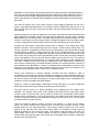
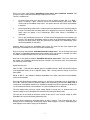
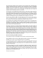
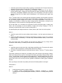
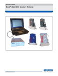
SmartGauge-SmartBank combination owners/installation manual
This manual covers use of both the SmartBank Standard and the SmartBank Advanced when
used in conjunction with the SmartGauge battery monitor. SmartGauge software revision r1.07,
r1.08, r1.09, r1.10, r1.11, r1.12, r2.01. R2.02
We have been forced to add the following warnings to this manual.
WARNING. Incorrect installation of this product may result in serious damage to the unit which
will NOT be covered under warranty.
Pay particular attention to the following:Incorrect battery polarity should not affect the unit. It simply will not work. However, if used in
conjunction with the SmartGauge, incorrect battery polarity will almost certainly damage one or
both units. Such installation leaves very distinct tell tale signs in both units and will NOT be
covered under warranty.
Use of the incorrect type of communications cable between SmartGauge and SmartBank may
damage one or both units. Such damage will NOT be covered under warranty.
No matter how careful you think you are NEVER attempt to carry out any work, whether
installation or modification, to any live electrical circuits. Disconnect ALL forms of power before
doing any installation or modification work. Failure to adhere to this simple rule will almost
certainly result in damage to the equipment which will NOT be covered under warranty. It only
takes one simple slip with a screwdriver or wire for just one nanosecond to do several hundred
pounds-worth of damage.
The C1 and C2 terminals carry POWER signals to the relay coil. Short circuiting these together
and/or to the battery positive or battery negative will almost certainly damage the unit. Quite
possibly beyond repair. Such damage will NOT be covered under warranty.
If using an SW180-2 relay pay particular attention to the relay coil terminals. There are not 4
terminals. There are 2. The opposite posts of each terminal are the same conductor. Connecting
C1 and C2 to the opposite sides results in a short circuit on C1 and C2. This will result in
irrepairable damage to SmartBank. Such damage will NOT be covered under warranty
If used in conjunction with SmartGauge, failure to provide a proper negative connection to the
GND terminal will almost certainly result in irrepairable damage to SmartGauge which will NOT
be covered under warranty.
Remember, we designed this product. We know it inside out, we know what every single
component does and know exactly what can cause what symptoms. If the unit is damaged as a
result of incorrect installation we WILL know and will NOT cover it under warranty.
Please, for your own benefit, heed these warnings.
1
SmartBank is a split charge control system based on the simple principle of paralleling batteries
when they are being charged and disconnecting them when they are being discharged. This is a
very common method of split charging batteries from a single charge source however various
factors make this type of operation using SmartBank unique and somewhat more sophisticated
than usual.
Let's start by taking a look at the various options for split charging. Basically they fall into 2
groups, relay based and diode based. The problems with the diode based solution are, in the
main, fourfold (there are many, many other problems with split charge diodes but these are the
most serious).
Firstly the diode can only split the charge from one source. So assume the split charge diode has
been installed in the alternator output. This means that the alternator can now charge 2 separate
battery banks from one charge source. If another charger (say an AC powered charger or a wind
turbine) is connected to one of the battery banks, no charge will appear on the other battery bank.
In order to charge the other battery bank another means of split charging has to be installed.
Secondly the diode drops a substantial voltage whilst in operation. This voltage drop varies
between around 0.5 volts at light charge rates up to around 1.4 volts at heavy charge rates. This
creates 2 problems, it represents a serious amount of wasted power, power that should be going
into the batteries. Instead it is simply wasted as heat, a very substantial amount of heat. Split
charge diode manufacturers and suppliers will deny this, however, if they don’t waste power in the
form of heat, why do they have such huge heatsinks on them? Even worse is that the voltage as
seen by the batteries is now much lower than the charge source believes it to be. This severely
reduces the charge rate into the batteries. A 1 volt drop in charge voltage can easily translate to a
75% drop in charge current! Some means to compensate for this voltage drop is required, the
most common solution being an external alternator controller. An external alternator controller is
more expensive than SmartBank, is orders of magnitude more complicated to install and only
cures one of the problems. Also, many alternator suppliers will not honour the warranty if the
alternator has been tampered with in order to fit an external controller.
Thirdly (even assuming an external alternator controller has been installed in order to
compensate for the voltage drop across the diode) the voltage drop across the diode varies as a
function of the current through it and this means that one battery will be correctly charged whilst
the other will either be severely overcharged or severely undercharged. There is nothing that can
be done to correct this problem with diode splitters.
Finally, if a “combi” (inverter/charger combination) is being used there is no way to charge the
other battery bank. Quite simply nothing can be done about this problem.
The other common option is a battery paralleling relay energised from the engine driven
alternator. This solution suffers none of the problems associated with the split charge diode
“solution” apart from the fact that it will only split the charge from the alternator. When another
charge source is introduced, it does nothing and only one battery bank gets charged. More
serious is the problem that many new alternators simply do not have the old “D+” or “ind” terminal
commonly used to energise this relay.
There is in actual fact another “solution” and that is the manual “1, 2, both, off” type battery
switch. This option actually works extremely well, far better than the diode solution. It does
however suffer one very serious drawback. If the operator forgets to switch over to the correct
position at the right time then either entire battery banks go uncharged or both banks get
discharged leaving no way to start the engine. This problem could also arise in the case of a
failed charger. This is the 21st century! Should we really be considering manual, error prone
systems when fully automatic state of the art systems are available that are simpler to install and
not that much more expensive?
2
SmartBank cures all these problems once and for all. It is installed once and will then, forever
after, take care of your split charge needs, totally automatically, whatever else changes in the
system, however the system is operated.
SmartBank splits the charge from any charge source to any battery bank. Totally automatically.
SmartGauge and SmartBank in combination
SmartGauge incorporates an RJ11 socket in the rear access panel for interfacing to the
SmartBank split charge system.
With the introduction of the SmartGauge - SmartBank combination, this sophistication has now
been taken one step further.
There are 2 types of SmartBank available for use with SmartGauge:
SmartBank Standard.
This is the totally self contained SmartBank split charge system that operates independently of
SmartGauge. When connected to SmartGauge, SmartGauge operates as a remote monitor
displaying the current status of SmartBank by way of the front panel LEDs. In addition
SmartGauge will display various errors if and when problems arise in SmartBank or the split
charging installation. These errors alert the user to problems such as a faulty relay, faulty relay
wiring, incorrect settings inside SmartBank or communication failures between SmartGauge and
SmartBank.
Also, the front panel buttons on SmartGauge permit a manual “emergency connect” to force
SmartBank to parallel both battery banks to enable the engine to be started from the auxiliary
battery bank.
SmartBank Standard can be modified to become a SmartBank advanced to enable the extra
functions to be utilised. Full details are available in the technical section of the website at
www.smartgauge.co.uk
SmartBank Advanced.
This is a slave type device to operate the split charge relay system in the same way as the
SmartBank Standard but in this case all control comes from SmartGauge. SmartGauge has many
extra features over and above those of SmartBank standard. SmartBank Advanced is physically
identical to SmartBank Standard and the user connections remain the same. Unlike SmartBank
Standard, SmartBank Advanced will not operate alone. It merely operates as a slave device
controlled by SmartGauge.
SmartBank Standard can be modified to become a SmartBank advanced to enable the extra
functions to be utilised. Full details are available in the technical section of the website at
www.smartgauge.co.uk
3
General SmartBank operation
A 4 way RJ11 lead connects between the remote socket on the SmartBank (either the SmartBank
Standard or the Advanced unit) and the RJ11 socket on the back of the SmartGauge.
IMPORTANT NOTE
There are four types of RJ11 lead commonly available. One group uses 4 conductors, the
other group uses 6 conductors but both use the same type of connector. SmartGaugeSmartBank communications will operate with either the 4 or 6 conductor types.
IMPORTANT NOTE
Of these 2 groups (4 conductor or 6 conductor), each has 2 different types. One is generally
referred to as “straight through” or “straight wired”. In this type, pin 1 of one end is connected
to pin 1 of the other end. Pin 2 is connected to pin 2 etc. This type will NOT operate with
SmartGauge-SmartBank and may damage either or both units. The other type is by far the
most common, in this type, commonly referred to as “cross wired”, pin 1 of one end is
connected to pin 6 of the other end, pin 2 goes to pin 5, etc. i.e. each end is a mirror image of
the other. This is the type required. These leads are available from your SmartGauge
supplier.
Clarification note.
The 4 and 6 conductor types use the same connector at each end, so the 4 conductor cable
does not use the outside 2 pins of the connector. The 4 conductor type uses pins 2, 3, 4 and
5. SmartBank-SmartGauge communications only uses the middle four conductors.
IMPORTANT NOTE
Attempting to extend a “cross wired” RJ11 lead by use of a back to back socket and another
lead will result in turning the lead into a “straight through” RJ11 lead which will not work and
may damage SmartGauge or SmartBank.
IMPORTANT NOTE
The maximum acceptable lead length is 10m. Leads longer than this may cause
communication errors between SmartGauge and SmartBank.
NOTE
Fleet operators or builders will probably find it cheaper and more convenient to obtain their
own crimping tools, cable and connectors and make up their own leads on site. This,
obviously, would not be viable for a single installation (the crimping tool alone would probably
cost more than a lead).
Once the correct lead has been obtained…….
On plugging this lead in (assuming the rest of SmartBank has been connected correctly),
SmartGauge will auto detect which type of SmartBank has been installed and display either
“Sb S” in the case of SmartBank Standard or “Sb A” in the case of SmartBank Advanced (or a
SmartBank Standard that has been modified to a SmartBank Advanced).
The functions and features for each unit are different and selected automatically by SmartGauge
depending upon which type of SmartBank has been detected. The user/installer does not have to
select the correct type.
4
Refer to the flow chart headed “SmartGauge setup menu with SmartBank Installed” and
compare it with the standard SmartGauge setup menu flow chart.
There are 3 differences:1.
On entering the setup menu the first item is now an option to select “Su 1” or “Su 2” Setup 1 or Setup 2. “Su 1” continues onto the normal SmartGauge setup menu. “Su 2”
moves onto the SmartBank setup menu. This option does not exist unless a SmartBank
is installed.
2.
On the SmartGauge setup menu, a further option has appeared on the Secondary Alarms
function. This allows the Secondary Alarm to be triggered by errors from SmartBank. This
option does not appear in the SmartGauge setup menu unless a SmartBank is
connected.
3.
Also on the SmartGauge setup menu, a further option has appeared on the display type
function. This allows any SmartBank activity to wake up the SmartGauge display when it
has gone into sleep mode. Again this option does not appear in the SmartGauge menu
unless a SmartBank is connected.
Selecting “Su 2” will enter the SmartBank setup menu. The items on this menu depend upon
which type of SmartBank has been connected to SmartGauge.
Refer to the flow chart headed “SmartBank Standard setup menu”. This is the setup menu that
will appear if a SmartBank Standard has been installed. Only one function is available, the ability
to enable or disable SmartBank errors. Not all errors can be disabled.
Now refer to the flowchart headed “SmartBank Advanced setup menu”. This is the menu that
will appear if a SmartBank advanced has been installed. You will notice there are considerably
more functions on this menu.
Specifically they are:“dt F” or “dt L” – This selects the display type for SmartBank activity. “dt F” will show Full reports
of all SmartBank activity on the 7 segment display. “dt L” will only show the activity via the front
panel LEDs
“EC 0” or “EC 1” – this enables or disables SmartBank error codes. Note that not all SmartBank
errors can be disabled.
Note that with SmartGauge software revision r1.11 and later, if the display type for SmartBank is
set to “dt L” AND error codes are disabled (“EC 0”) then SmartGauge will not report Sb A or Sb S
on detection of SmartBank Advanced or SmartBank Standard and will not generate an E 10 error
on communications failure with SmartBank. In certain installations this is desirable.
The next display looks just like a normal voltage display. In actual fact it is, because this is the
nominal voltage at which SmartBank will disconnect the battery paralleling relay.
The next item is the same as the above except in this case it is the nominal voltage at which
SmartBank will connect the battery paralleling relay.
Note that these voltages are described above as being “nominal”. This is because they are a
starting point for SmartGauge. SmartGauge adjusts these voltages “on the fly” depending upon
what happens to the state of charge of the batteries.
5
Also note that these voltages are set by default as a part of the battery type. If the battery type is
changed, SmartGauge will load in the default connect and disconnect voltages for SmartBank
operation for that particular battery type. They can be changed by the user by entering the
SmartBank setup menu. Whichever was changed last will take precedence. Note that simply
looking at the battery type will not load in the defaults. The battery type has to actually be
changed in order for the previous values to be overwritten.
The next option is the SmartBank high voltage disconnect. If either battery voltage reaches this
level SmartBank will disconnect the relay to prevent damage to the other battery. The battery
voltage has to fall back down below this level in order for the relay to be reconnected. There is
some hysteresis built into this setting. The battery voltage actually has to fall below the high
voltage setting by 0.1 volts or more in order to reconnect. The factory default for this setting is
16.00 volts. The adjustment range is the SmartBank connect voltage up to 16.50 volts.
The next option is “b2 E” or “b2 A”. This allows battery 2 to be set as either another Auxiliary
bank or as an Engine start battery. The algorithms SmartGauge uses to decide when and when
not to operate the split charge system depend upon which type of battery it is set to.
If set to Auxiliary then SmartGauge treats both batteries in the same way. If set to Engine start,
SmartGauge gives charging priority to the engine start battery when the charge source is
connected to the engine battery. What this means in practice is that after a vehicle or boat has
been started, the engine driven alternator will charge the engine start battery first before the
power is diverted to the auxiliary battery bank.
This helps to ensure that, no matter what heavy loads are placed on the system overall, the
engine battery always receives sufficient charge to replenish what was removed in starting the
engine. SmartGauge achieves this by delaying the time before connecting the battery paralleling
relay. The time of this delay varies drastically depending upon the charge voltage, the rate of
change of engine start battery voltage, the charge status of the auxiliary battery bank, the size of
the alternator and several other measurements and calculations. During this “Engine Priority” time
SmartGauge will be displaying the normal display (either volts or status) alternating with “EP” for
Engine Priority. The time of this priority can vary between about 90 seconds and 35 minutes
depending upon the factors described above. Note that if the charge source is connected to the
auxiliary bank, Engine Priorty charging will not take place.
Advanced SmartGauge-SmartBank installations
That completes the setup of the SmartBank functions and the use with twin battery banks.
Some installations utilise more than 2 battery banks and there are various ways SmartGaugeSmartBank can be used to control charging/monitoring of such installations.
The SmartGauge would normally be installed so that it monitors the charge status of the most
commonly used auxiliary bank. i.e. this battery bank would be installed as battery 1. This allows
the charge status of the main auxiliary battery bank to be monitored and all alarm functions to
operate on this battery bank.
The choice of which battery to connect in as battery 2 depends upon how the system will be
used. Normally battery 2 would be connected to the engine start battery. When used in
conjunction with SmartBank Advanced this allows full engine start priority charging to take place
which is an advantage probably not wisely lost. However the disadvantage is that the battery
voltage of the second auxiliary battery cannot be monitored. This may or may not be an issue
depending upon the installation and it’s use.
The choice comes down to:-
6
1.
2.
Install the system with the engine battery as battery 2 and benefit from full engine start priority
charging but lose the ability to monitor the 2nd auxiliary bank voltage.
Install the system with the 2nd auxiliary bank as battery 2 and benefit from the ability to
monitor auxiliary bank 2 voltage but lose the benefits of engine start battery priority charging.
Remember, a SmartBank Standard will still have to be incorporated in this case in order to
split the charge from the battery which SmartGauge is not monitoring (the engine start
battery).
If the 2nd auxiliary bank is only used for light duty equipment (perhaps communications equipment
in an emergency vehicle) then the charge status of this battery is probably never an issue as it
will be receiving regular charges far in excess of it’s actual requirements. In this case it is
probably not necessary to monitor the battery voltage and B2 would better be utilised on the
engine battery in order to benefit from full engine start priority charging.
On the other hand, if it is considered very important to monitor the auxiliary bank 2 voltage, then
either it will be necessary to lose the benefits of engine start priority charging or it will be
necessary to install another meter to monitor auxiliary bank 2.
As regards splitting the charge between the 2 battery banks, again, there are various options.
Option 1
A. Install the system with the main auxiliary bank as battery 1 and the engine start battery as
batt 2.
B. Install a SmartBank Advanced controlled by SmartGauge operating 2 relays. One connected
between battery 1 and battery 2. The other relay connected between battery 1 and the 2nd
auxiliary battery.
This gives engine start priority charging and will split the charge from any charge source
connected to either battery 1 or battery 2 to both the other 2 battery banks.
Option 2
A. Install the system as above but with a single battery paralleling relay. The system will operate
exactly as above except the 2nd auxiliary bank will never be charged.
B. Now add a SmartBank Standard connected between battery 1 and the 2nd auxiliary battery
bank.
This system, although more expensive, is probably close to the ultimate in split charging 3 battery
banks. Full charge priority is given to the engine start battery. Secondary charge priority is given
to the 1st auxiliary bank, with the system finally charging the 2nd auxiliary battery bank. Due to the
various parameters that can be adjusted on SmartBank Advanced and SmartBank Standard, the
priority level can be set to suit any and every possible combination of battery types, installation
and use.
Also, any charger, connected to any battery will ensure all 3 battery banks are charged.
Finally there is…
Option 3
A.
B.
Install the system as per A in option 2 above.
In addition another SmartGauge-SmartBank Advanced combination is installed
monitoring the 2nd auxiliary battery bank as battery 1 and the 1st auxiliary battery bank as
battery 2.
7
This final option, being the most expensive and complicated to install, has all the advantages of
option 2 but in addition also displays the charge status of the 2nd auxiliary bank. We have only
ever been involved in 3 installations of this type. One was in the SmartGauge designer’s own
boat, one was on a test rig in the workshop and the third was on a customer’s RV. The systems,
whilst being somewhat expensive and complicated to install (and understand) worked beautifully
allowing anything to be adjusted but also relying upon the intelligence of the SmartGaugeSmartBank combination to make up for setup errors.
Existing SmartBank installations
For those adding a SmartGauge to an existing SmartBank installation there are basically 2
options.
A.
Keep the setup as it is currently installed and simply connect SmartBank to SmartGauge
with the plug in RJ11 lead. This allows SmartGauge to display the status of SmartBank,
adds the remote emergency connect function and also adds error reporting if problems
arise with SmartBank or the split charge system in general.
B.
Convert the SmartBank Standard already installed to a SmartBank advanced and benefit
from all the extra features the SmartBank advanced has.
Details for conversion of SmartBank Standard to SmartBank Advanced are available in the
technical section of the website at www.smartgauge.co.uk
SmartBank error codes:E 10
E 11
E12
E13
Communication has been lost with SmartBank. The RJ11 cable has probably been pulled
out or damaged. With a SmartBank Advanced, split charging will cease to function. With
a SmartBank Standard, split charging will continue to operate as usual, you just won’t
know about it.
SmartBank, (either by it’s own decision in the case of SmartBank Standard or under the
control of SmartGauge in the case of SmartBank Advanced) has attempted to operate the
split charge relay but SmartGauge is measuring different voltages on the 2 batteries. This
would indicate either a faulty relay or faulty relay wiring. In either case, split charging is
probably not taking place.
Electronic Overload in SmartBank. This error is very rare.
SmartBank Standard has connected but the disconnect preset adjustment is set higher
than the connect preset adjustment. This is incorrect. SmartBank will probably cycle
between states for some considerable time. Reset the adjustments according to the
SmartBank owners/Installation manual. This error only applies to SmartBank Standard.
You will never see it on a SmartBank Advanced because the setup menu will not permit
the disconnect voltage to be set higher than the connect voltage.
Note that error codes relating to SmartGauge begin with zero, those relating to SmartBank begin
with 1.
Disabling the SmartBank error codes in the SmartBank setup menu will disable E11, and E13.
Note that E10 and E12 cannot be disabled.
The reason E11 can be disabled is to prevent nuisance error reports in poor installations where
the cabling between the 2 battery banks is insufficiently sized. Also, some professional installers
use the SmartGauge/SmartBank combination for purposes other than split charging and in some
of these instances, the closure of the relay does not necessarily mean that both battery banks
should be at the same voltage.
The reason E13 can be disabled is that some professional installers use some clever SmartBank
tricks that require them to set the connect and disconnect presets to values that would otherwise
be incorrect.
8
General operation of SmartGauge/SmartBank combination.
SmartBank Standard AND SmartBank Advanced.
Error codes are identical for each unit with the exception of E13 as detailed above. This error will
never show with a SmartBank Advanced.
Pressing the Volts button for 5 seconds will force an Emergency Connect in order to permit the
auxiliary battery bank to be used to assist engine starting. This is a timed connect that will
disconnect after 30 seconds. Also, if Primary and Secondary alarms have not been set, this
Emergency Connect will trigger the alarm output. If any sort of alarm has been set on
SmartGauge, then the Emergency Connect will not trigger the alarm output. This is a feature
added for certain professional fleet operators and is probably not a feature that will be utilised by
most people. See Note 1 in the addendum.
When first connected SmartGauge auto-detects SmartBank and displays “Sb S” or “Sb A” for
Smartbank Standard or Smartbank Advanced respectively.
If SmartGauge loses communication with SmartBank (probably the cable has been pulled out or
damaged) SmartGauge will show an E 10 error.
Whenever a SmartBank is connected to SmartGauge, the green SmartBank/SmartInterface LED
will blink briefly once per second when in standby mode. Whenever SmartBank is operating the
split charge system this LED will be on solid, irrespective of any other settings.
SmartBank Advanced only.
Assuming “dt F” (display type Full) is selected:Forcing a manual connect will alternate the display between the normal display and “EC”
(Emergency Connect) for the period of the emergency connect (30 seconds).
When SmartGauge has detected a valid charge source the display will alternate between the
normal display and “CP” – Connect Pending.. The time from this display appearing to SmartBank
actually operating the split charge system is dependant upon many factors and will vary
considerably, particularly dependant upon battery voltage, charge status and the size of the
charger.
When SmartBank is operating the split charge system the display will alternate between the
normal display and “Con” – Connect
When in connect mode and SmartGauge has detected the charge source may have been
switched off (or a load that exceeds the capability of the charger has been connected) the display
will alternate between the normal display and “dP” – disconnect Pending.. The time from this
display appearing to SmartBank actually disengaging the split charge system (in order to prevent
cross discharging) is dependant upon many factors and will vary considerably, particularly
dependant upon battery voltage, the size of the load and the size of the charger..
Immediately following connection of the split charge system it may be the case that a deeply
discharged auxiliary bank will drag the overall voltage below the disconnect voltage and ordinarily
SmartGauge would therefore almost immediately separate the batteries (as a normal simple
voltage controlled relay would do). SmartGauge can sense this situation and if this occurs
SmartGauge will hold the batteries connected for a certain period (known as the “Hold” time) to
9
enable the auxiliary battery voltage to rise above the disconnect level. The time of this “Hold”
function varies and is calculated on the fly. When this function is active the display will alternate
between the normal display and “Hold”. Note that the “Hold” display will only be active if the
function is actually holding the split charge system active at a time when, ordinarily, it would have
disconnected. This feature is similar to the Hold function in SmartBank Standard but in the case
of a SmartGauge - SmartBank Advanced combination it is far more sophisticated.
If B2 is set to Engine start (“b2 E”) and a charge source is applied to this battery then engine start
battery priority charging will take place automatically. Whilst this is active the display will alternate
between the normal display and “EP” – Engine Priority. The time of this Engine Priority will vary
drastically between about 90 seconds and 35 minutes depending upon the state of charge of all
the batteries, the size of the connected charger etc. It is totally automatic and calculated
continuously “on the fly”.
If SmartGauge/SmartBank advanced has disconnected the relay due to the battery voltage
exceeding the high voltage disconnect level, the display will alternate between the normal display
and “HU d” – High Uoltage disconnect. The flashing of the SmartBank LED will also be
completely different. In standby this LED blinks very briefly once per second. During high voltage
disconnect the LED flashes alternately on and off with equal times on each state.
Most of these displays may only be required during initial setting up of the system. Indeed some
people may consider them to be a nuisance in normal use. For this reason they can all be
disabled. Simply enter the SmartBank setup menu and switch the display type from Full (“dt F”)
to LEDs only (“dt L”).
Do’s and Don’t’s
Do not expect a SmartGauge - SmartBank combination to operate as a simple voltage controlled
relay. It is far more sophisticated than that. Just because a human, following a cursory glance or
prod with some meter probes, thinks it should be operating the split charge system does mean it
should. SmartGauge takes over 30 measurements and makes tens of thousands of calculations
every second. It is far better at deciding when to operate the split charge system than any human
could ever be.
Do not be alarmed and assume a fault if the battery paralleling relay is alternating between
connected and disconnected. This is not a fault in SmartGauge or SmartBank. It could be that the
system is doing exactly what it is supposed to do. i.e. preventing cross discharging between
battery banks. But it is possible that it is the result of either incorrect settings (connect and
disconnect voltages set too close) or far more likely, a charger that is simply far too small for the
total batteries in the system. Even with a charger that is too small, it is usually possible to find a
compromise in the settings that allows the system to operate until the charger is replaced with
one of the correct size.
Fleet operator functions
Alarm on emergency connect
As noted in the main section of this manual, if no alarms have been set of either Primary Alarm
type or Secondary Alarm type then, whenever the emergency parallel function is invoked, the
alarm output will trigger. The alarm output will remain triggered for the period of the emergency
connect. This feature can be utilised by fleet builders to inhibit functions of other equipment
during the emergency connect period or to trigger an audible alarm whenever the emergency
connect function is used.
Defeating engine start battery priority charging.
1
For some reason, many fleet operators think that the Engine Priority charging function prevents
their auxiliary battery bank from receiving instant charge immediately following vehicle engine
start. If this happens it is not because of the priority charge function. It is because the alternator is
not big enough to charge the auxiliary bank and the discharged engine battery. If the alternator
was big enough to charge both battery banks, the Engine Priority function would not be active!
The Engine Priority function only operates if the alternator is not big enough to charge both flat
battery banks. The correct solution is to increase the size of the alternator. However, if you insist
in this incorrect assumption then the engine battery priority charge function can be defeated by
setting battery 2 as being an auxiliary battery instead of an engine start battery (at the end of the
SmartBank Advanced setup menu).
This is not recommended by us as it may, under extreme circumstances (i.e. in very cold weather,
with a poorly engine, tired heater plugs and lazy starter motor), mean that the engine battery
receives insufficient charge to ensure reliable engine starting on the next start.
The same fleet operators are usually under the misapprehension that this situation would not
arise in the case of the same installation using a diode split charge system. This simply isn’t the
case. Exactly the same situation would arise (i.e. the auxiliary bank would not receive any charge
until some time after the engine had been started), the only difference would be that the operator
of the vehicle would not be aware that the auxiliary battery was not being charged.
For professonal installers only – defeating power save.
The pulse width modulation power-save feature of SmartGauge-Smartbank can be defeated. Full
details are available in the technical section of the website at www.smartgauge.co.uk
1
The SmartGauge setup menus are different once the unit is interfaced to SmartBank. This is to
prevent the setup menus confusing the user when no SmartBank is installed.
The menu flowcharts will change as follows:The main SmartGauge setup will have additional functions thus:-
1
With a SmartBank Standard installed the SmartBank Setup menu (Su 2) will look like this:-
1
With a SmartBank Advanced installed the setup menu will look like this:-
[071004]
1