1
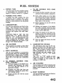
BRAKES
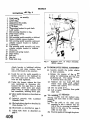
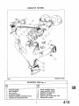
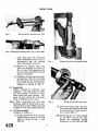
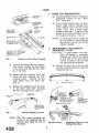
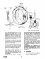
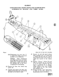
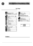
Exploded view of Front Brake d e w ,
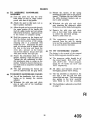
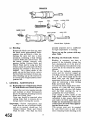
25. TO FIT FRONT
(a) Mount the wheel cylinders on the
back plate and secure each with a
bolt and lock washer.
(a) Fit the smaller end of the coil spring
over the projection in the cup filler and
insert both parts into the cylinder
body, with the spring leading.
(b) Connect bridge pipe to bottom
(b) Follow up with the rubber cup, lip
end foremost, taking care not to damage
or turn back this lip.
bore of each wheel cylinder, utilising
the union nuts trapped on the pipe.
Ensure that the pipe is located on its
seat before attempting to attach the
nut. Tighten nut sufficiently to give
and oil and air tight joint.
(c) Attach the flexible hose to the upper
bore of the rear cylinder, checking
fist that the copper-gasket-isin good
order. Fit flexible hose to bracket
on the chassis frame as describe
page 5.
(d) Fit bleed screw to upper bore of
front wheel cylinder.
(e)
Fit brake shoes, taking care to locate
the " micram" adjusters in the slots
in the leading tip of each shoe, with
the masks in position.
) Fit brake drum and bleed hydraulic
system as described on page 3.
(g) Adjust brake as described on page 3.
Check the system for fluid leakage by
applying a firm
sure to the pedal
and .inspecting
pipe line and
connections,
(i) Fit road wheel and nave plate. Rem~ve
jacks.
E FRO
EL
CYLINDER
raw the piston complete with
piston cover from cylinder body.
26, TO DIS
(b) Apply low air pressure to the flexible
hose connection, the rubber cup, the
cup filler and spr g can readily
be removed.
27. T
LE FR
EEL
C
Ensure absolute cle
assembly of these CO
parts
a generous coating of dean
LocWl
rake Fluid.
(c) Feed in piston with cover in position.
28.
RE
EL CYLINDER
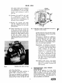
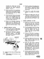
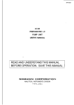
Description
The cyhder, which is fitted in an elongated
slot in the rear brake plate, is free to slide in
the slot between the tips of the brake shoes
which are of the leading and trailing shoe
type. The cylinder has a single piston
operating on the tip of the leading shoe and
this shoe abutts against a fixed anchor
block at the bottom of the back plate, the
web of the shoe being free to slide in
a slot in a block. The trailing shoe is
in a similar manner b&een the
and the closed en of the cylinder
a d is free to slide and therefore self
centring.
The trailing shoes are operated by movement of the reaction of the leading -shoe
against the brake drum. A " micram"
adjuster is located in a slot in the top of
The wheel cylinder contains a single piston,
split in two, the inner piston being
hydraulically operated while the outer
piston is manually operated by the hand
brake lever. A rubber cup mounted in the
cup Mler is loaded upon the inner piston
by a spring. When operated hydraulically,
the inner piston abuts against the outer
piston leaving the handbrake lever undisturbed, and applies a thrust to the tip of the
leading shoe through the dust cover,
micram adjuster and mask. When operated
manually, an inward movement of the hand
brake lever brings the head of the contact
lever into contact with the outer piston,
thrusting it outwards against the leading
shoe without disturbing the inner piston.
er boot is fitted to exclude water
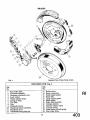
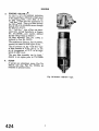
Fig.
4 L& washer.
5 Wheel cylinder body.
6 Spring in body.
7 Cup filler.
Exploded view of Rear B
BRAKES
29. TO WEMOVE REAR WHEEL
CYLINDER
(a) Jack up rear of car. Remove nave
plate, road wheel and brake drum.
Slacken off micrarn adjuster.
(b) Drain ofi hydraulic fluid, disconnect
handbrake cables and remove banjo
bolt from banjo connection which is
situated on the inner side of the brake
plate.
Pull the trailing shoe against the load
of the pull-off springs and away from
its abutment at either end; on releasing
tension of the pull-off springs the leading shoe will fall away. Collect the
micrarn adjuster and mask.
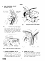
( d ) Remove the rubber boot and the handbrake piston.
(g) Swing the handbrake lever until the
shoulder is clear of the back plate and
slide the cylinder casting forward.
Pivot the cylinder about its forward
end and withdraw its rear end from
the slot in the back plate. A rearward
movement of the cylinder will now
bring its forward end clear of the back
plate.
(c)
30. TO FIT REAR WHEEL CYLINDERS
(a) Offer up the rear wheel cylinder to
the back plate with the handbrake
lever to the slot. Engage the forward
end of the cylinder in the slot and slide
it well forward, taking care to position
the lever so that the shoulder clears
the back plate. Engage the rear end of
the cylinder in the slot and slide it
back to hold it in position.
(b) Place the rubber boot over the handbrake lever and ease the boot round the
wheel cylinder so that it provides
maximum weather protection. Connect
handbrake cable to lever, utilising a
new split pin for the securing of the
clevis pin.
(c) Mount the banjo connection with new
copper gaskets on the wheel cylinder
and secure with banjo bolt.
(d) Assemble the brake shoes, ensuring that
the rnicrarn adjuster is in the slot in
the leading shoe with the mask in
position. Fit the brake drum.
(e)
Bleed the hydraulic system as described
on page 3. Adjust the brake shoes
as described on page 3.
(f) Check the system for fluid leakage by
applying firm pressure to the pedal
and inspecting the line and connections.
(g) Fit road wheel and nave plate. Remove jacks.
31. TO DISMANTLE REAR WHEEL
CYLINDER
(a) Withdraw the piston complete with
piston cover from the cylinder body.
(b) Remove the seal from the piston by
easing out of its groove.
(c)
Drift out the handbrake lever pivot
pin to remove handbrake lever.
( d ) Apply low air pressure to the
inlet connection, the rubber cup, the
cup filler and spring can readily be
removed.
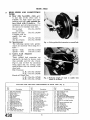
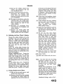
SEAL
Fig. 7
32.
Sectional view of Rear Wheel Cylinder.
TO ASSEMBLE REAR WHEEL
7)
CYLINDER (Fig.
Ensure absolute cleanliness during the
assembly of these components. Assemble
hydraulic parts with a liberal smear
of clean Lockheed Brake Fluid.
(a) Fit the smaller end of the coil spring
over the projection in the cup filler and
insert both parts into the cylinder
body with spring leading.
Follow up with the rubber cup, lip
end forward, taking care not to damage
or turn back this lip.
Insert hydraulic piston into body
ensuring that the slot coincides with
the lever slot in the cy
Place the handbrake lever in position
and fit pivot pin.
Stretch the handbrake piston rubber
seal over the handbrake piston and
place with dust cover in cylinder
body, ensuring that the hand lever is
engaged in the slot of
The seal is to be twisted on
that the edge which tends t
from the groove enters the bore last.
(b) Remove brake shoes and collect pulloff springs and adjusters.
(c) Fit the replacement shoes and new
pull-off springs after ascertaining that
the brake linings are of the same
material (see page 2).
brake drum and adjust brakes as
cribed in page 3.
.
). Remove fow nuts and lock was
from front end of master cylinder
bracket adjacent to pe
lock washer.
also be remove
d.
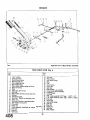
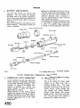
NOTATION FOR Fig. 8
Pedal shaft cover assembly.
Clutch pedal.
Brake pedal.
Rubber pad for pedals.
Pedal pivot bush.
Pedal shaft.
Supporting bracket for pedal shaft.
Lock washer.
Bolt securing brackets to shaft.
return spring.
washer.
cylinder support bracket to bulkhead.
Lockwasher.
Nut securing pedal assembly and master
cylinder support bracket to b
Clevis pin.
Double coil spring washer.
Plain washer.
t stop.
Fig. 8
Attach bracket to bulkhead utilising
four nuts and plain washers, these
nuts are left loose at this juncture.
Inside the car the pedal assembly is
further secured to the b
two bolts and lock washers, these
bolts are fully tightened.
Under the bonnet, tighten the four
nuts mentioned in operation
Connect the two pipe lines to
priate outlet ports and attach
levers to master cylinder fork
end assemblies, utilising clevis pins.
Adjust pedal clearances as described on
page 4.
Replenish reservoir with Lockheed
Hydraulic Fluid.
Bleed and adjust clutch as described in
Clutch Section "D
Bleed brakes as described on page 3.
(i) Adjust brake shoes as described on
page 3.
".
Exploded d e w of Pedal Assembly.
(R.H.S. shown.)
TO DPS
E PEDAL ASS
LY
(a) Suitably identify the pedals relative
to their positions.
e the tension of the return
by withdrawing end from the
anchoring tab. The spring can now
be removed from the pedal.
(c) Withdraw the two bolts and lock
washers from pedal shafi support
brackets and remove these brackets.
Drift out pedal shaft.
(e) Lift out pedal assemblies from pedal
shaft cover.
TO ASS
LE PEDALS
During assembly note the marked components and return them to their original
positions.
(a) Fit the pedals to the shaft cover
assembly in such a manner that the
wall of the cover pressing is accommodated in the recess in the revolving
collar on each pedal.
shaft through the pivots.
(c) Position the supporr brackets on the
shanks of the welded bolts and allow the
cut away side to drop into the recess
of the revolving collar. Slight pressure
may be necessary to bed this bracket.
(d) Secure the bracket to the pedal shaft,
utilising two bolts and lock washers,
one each side.
(e) Hook the return springs in the shaft of
the pedals and anchor the other to
the welded tab.
(d) Tighten the pivot bolt leaving the
lever freedom of movement and attach
the locking nut to the pivot bolt
from inside the cruciform. When
tightening this nut the head of the
pivot bolt must be held to ensure the
freedom of movement of the lever.
(e) Attach the fork end of the cable to the
brake lever and secure with clevis
pin, split pin and plain washer.
(f) Working inside the car,feed the draught
excluder on to the lever and secure to
floor with plate and three self tapping
screws.
LEVER
B
(a) Chock the wheels, jack up the car
and release handbrake.
(g) The tape can now be removed from
the thread and the bakelite grip screwed
into position.
(b) Remove the bakelite handle grip and
tape the thread for protection.
(h) Lower the car and remove chocks
from the wheels. No readjustment of
the handbrake should be necessary
as the lengths of the cables have not
been altered.
(c) Withdraw the three self tapping screws
securing the draught excluder plate
to floor. Remove plate and draw
draught excluder up the handbrake
lever.
(d) Working under the car, withdraw the
devis pin from the front fork end of
the handbrake cable after first removing split pin and washer.
(e) Release the tabs of the locking plate
and withdraw two bolts securing
attachment plate.
(f) Remove the nyloc nut, 10
bolt to chassis frame.
(g) Withdraw pivot bolt. The handbrake
lever can be drawn downward through
the floor.
41. TO
HANDB
LEVER
(a) Feed the pivot bolt through, first the
lever assembly and then the mounting
plate.
(b) Working beneath the car feed the lever
through the floor assembly and attach
lever to chassis by the pivot bolt
which is left loose at this juncture.
(c) Utilising two bolts and a locking plate
secure the lever mounting plate to the
and lock bolts with tabs
te.
+
y-0
DISMANTLE
BRAKE
(a) Remove the bakelite grip and protect
thread with tape.
(b) Detach the attachment plate from the
ratchet by removing the bolt and nyloc
nut.
(c) Remove the split pin and plain washer
from the clevis pin, applymg pressure
to the press button at the top of the
hand, withdraw clevis pin. This will
allow the ratchet to become disengaged
from the pawl and enable it to be with-
drawn.
(d) Releasing the pressure on the button
and allow it to protrude through the
lever casing under the influence of
the spring. Remove button from push
rod, followed by the spring and plain
washer.
rod and pawl can now be
from the lower end of the
with
lever and the pawl removed from the
push rod.
(e) The
I
BRAKES
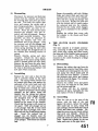
Exploded view of Hand Brake Assembly.
Fig. 9
NOTATION FOR Fig. g
Ref.
No.
I Ref.
I No.
Lever assembly.
25
Lever pivot bush.
26
Handbrake lever grip.
27
Pawl stop mills pin.
28
Pawl release push rod.
29
Pawl release spring.
30
Plain washer between spring and lever.
31
Push rod button.
32
Pawl.
33
Clevis pin, pawl to lever.
34
Split pin.
35
Plain washer between split pin and lever.
36
Ratchet.
37
Attachment plate.
38
Set screw. Ratchet to attachment plate.
39
Nyloc nut.
40
Set screw. Ratchet to attachment plate.
41
Tab washer on setscrews.
42
Pivot bolt.
43
Nvloc nut.
44
d b l e assembly (handbrake to mmpemating lever). 45
Fork end.
46
Jam nut.
47
Clevis pin.
1
Split pin.
Plain washer.
Anti-rattle spring.
Bolt.
Nut.
Lock washer.
Clevis pin.
Split pin.
Plain washer.
Compensator bar assembly.
Compensator lever assembly.
Grease nipple.
Felt seal.
R.H. cable assembly 12.97" long. 12.47" 10"
L.H. cable assembly 26.85" long. 26.35" brakes
Fork end.
Swivel pin.
Anti-rattle spring.
Split pin.
Jam nut.
Clevis pin.
Split pin.
Plain washer.
1
43. TO ASSE
LE H A N D B W
ASSEMBLY
(a) Feed the push rod into the lever
from below so that its shape corresponds with that of the handle.
(b) Attach the pawl t
sh rod so
that it points ream
(c) M o w the push rod to protrude through
the upper portion of the handle and
feed on a plain washer and coil spring,
followed by the button. Apply pressure
to the button to compress spring.
(d) Hold the pressure on the button and
feed the ratchet, teeth facing forward,
into the lower portion of the casing,
ensuring that it is positioned well
inside the lever. Manipulate the pawl
until its fulcrum hole is aligned with
the hole in the lever and insert the
clevis pin; pressure on the button
can now be released. Secure clevis pin
with plain washer and split pin.
(e) Secure the attachment plate to the
ratchet, utilising a bolt and nyloc nut.
Tighten the nut sufficiently to allow
the attachment plate to swing on the
ratchet. Failure to observe this instruction will result in imperfect handbrake
operation.
(f) The tape protecting the thread can
now be removed and the grip fitted.
B
(a) Let off the handbrake, lock the rear
brakes on by turning the micram
adjuster.
(b) Withdraw the split p
pins at each end of
cable assembly.
(c) Release the tension of the spring
securing the brake cable to the gearbox
tunnel. Withdraw the two bolts from
the cable abutment brackets and remove cable assembly.
(d) Withdraw the split pins and clevis
pins attaching the transverse cables
to the levers on the brake backing plate.
(e) Remove the split pins and clevis
pins at their inner ends, taking care
to collect the anti-rattle springs.
emove cables from car.
(f) The compensator assembly can be
removed from the axle by turning
lever and bar assemblies independently
in an anti-clockwise direction.
45.
BRAKE CABLES
The fitting is the reversal of the removal
but the following points should be noted :--
(a) The transverse cables should be of
the correct length. R.H. 12.97"+.06"
L.H. 26.85" f .O6". These measurements for 10" brakes are 12.47" and
26.35" respectively.
) All cables and fulcrums should be
thoroughly greased before fitting.
(c) The bar assembly is attached to the
e with a new felt seal and then
turned back one turn. This instruction
also applies to the lever assembly
when fitted to the bar assembly.
(d) The handbrake is adjusted as described
on page 3.
SECTION S
EXHAUST S
INDEX
Page
......
......
......
Notation for Figure 1 ......
Description
......
......
......
......
......
Maintenance ......
......
......
......
......
Exhaust System. T o remove and dismantle
Notation for Figure 3 . . . . . . . . . . . .
......
......
Exhaust System. T o fit
......
......
......
Manifolds To remove
......
......
......
Manifolds. T o fit
......
......
.....
......
.
......
......
......
......
......
..*...
......
......
......
......
......
......
......
......
......
......
1
2
2
2
3
......
......
......
......
......
4
4
.....
......
.....
4
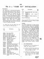
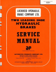
ILLUSTRATIONS
Fig . 1 Exploded view of exhaust system ......
Fig . 2 Fitting the auxiliary silencer
......
Fig . 3 Exploded view of manifolds. . . . . . . . . . . .
......
......
......
......
......
......
Page
1
2
...... 3
......
......
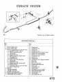
EXHAUST SYSTEM
Fig.
I
Exploded view of Exhaust System.
NOTATION FOR Fig.
Ref.
No.
1 Exhaust flange joint.
2 Front exhaust pipe.
3 Prior to Commission No. TS.4310 only :
A Attachment bolt to chassis.
B Flexible mounting strip.
C Clamp plate.
D Attachment nut.
E Exhaust pipe clip (Upper half).
F Clamping bolt.
G Attachment nut.
H Rubber and metal grommet.
J Clamp plate.
K Attachment bolt.
L Exhaust pipe clip (Lower half).
M Rubber washer.
N Attachment bolt (Lower half clip).
P Nut for clamp bolt.
4 Silencer.
5 Tail pipe assembly.
6 Tail pipe extension.
7 Flexible mounting strip.
8 Exhaust pipe support bracket.
9 Attachment bolt to chassis.
I.
Ref.
No.
Clamp plate.
Attachment nut.
Clamp bolt
Attachment nut.
Attachment bolt to chassis frame.
Rubber and steel grommet.
Rubber and steel grommet.
Attachment nut.
Clamp nut.
Clamp date.
~ttac'hr;lentbolt (Support bracket).
P i ~ ce l i ~ .
Phch &It.
Nut for pinch bolt.
Flexible mounting strip.
Pinch bolt.
Attachment nut.
Clamp plate.
Attachment bolt to chassis.
Pipe clip attachment bolt.
Nut for pinch bolt.
Clamp plate.
Clip attachment nut.
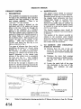
The manifolds are attached to one another
by studs in the aluminium alloy induction
manifold and lugs moulded in the cast
iron exhaust m
Id.
There is no
" hot spot "for easy starting.
The exhaust system is situated on the
side of the engine and passes
e rear of the car through the
centre of the crucifom to a position
adjacent to the left-hand chassis member.
The front exhaust pipe is attached to the
engine by a flange and is flexiblymomted to
e chassis frame at a point forward of
e cmciform centre. This attachment also
es the pipe to the outside of the
silencer.
Cars with Commission
.431Q and before has this clip in
ves as shown in Fig. 1.
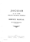
Two types of silencers have been used in
production, the former 118" silencer being
changed for a 24" type at Commission
No. TS.2532. A modified tail pipe incorg a 12" silencer can be fitted, at the
owner9s discretion, to the shorter type
silencer, if the exhaust note is considered
too loud (see Fig. 2).
This modified
tail pipe fits into the main silencer and is
attached with the existing clip.
At the rear the tail pipe is attached to the
chassis by a flexible mounting strip and the
clip secures the chromium plated extension
piece inside the tail pipe.
The exhaust system should be inspected
periodidy to ensure its correct function.
Attention should be paid to the gaskets at
the cylinder head, carburettor and front
exhaust pipe flanges to ascertain their
condition. If signs of " blowing " are
detected then gasket must be replaced as
soon as possible. Manifold gaskets should
be replaced as a pair and no gasket should
ever be used twice..
The flexible mounting strips should be
inspected and replaced if any deterioration
is apparent.
The position of the silencer assembly in
relation to the cruciform centre should
always be such that during any vibrationary
period the exhaust system cannot come
into contact with the cruciform.
3.
T
MOVE AND DISlMANTLE
E
ST SYSTEM
(a) Working from the rear of the car
loosen the bolt of the rear pipe clip
attachment and withdraw exhaust pipe
extension.
(b) Withdraw the lower bolt securing
pipe clip attachment to flexible mounting strip and collect nut and lock
washer.
( c ) Loosen the pinch bolt of the pipe
clip attachment at the rear of the
silencer and withdraw tail pipe
assembly.
RT N o 108446
SILENCER 8 PlPE
EXISTING IkSTALLATIC
PART N O 2 0 I boo ( 1 8 LONG)
- OR
-
/
PART N' 2 0 2 3 2 0 ( 2 4 " ~ 0 N G )
F I T T E D TO LATER C A R S
i:
\
THIS PlPE IS CARRIED ON EXISTINQ
TAIL P l P E MOUNTING
EXHAUST SILENCER (IZ'LONC)AND TAIL PlPE
PART NQ 2 0 2 2 8 5
REPLACING TAILPIPE
Fig.
2
Method of supplemen
PART NQ2 0 2 0 0 9
rovided by 18" Silencer, fitted prior to Com. No. T.S.259.
anifold details.
Fig. 3.
Ref.
No.
2 Inlet manifold.
3 Joint washer.
4 Insulating washer.
5 Exhaust manifold a t t a c h
6 Carburettor attachment S
12 Flange joint washer.
EXHAUST SYSTEM
(d) Loosen the pinch bolt (or bolts)
forward of the cruciform centre and
withdraw the silencer rearward.
(e)
Remove the lower bolt attaching
flexible mounting strip to chassis frame.
Remove the nut and bolt, collecting
the rubber grommet and rubber washer
securing the bracket to the chassis
frame.
(c) If the tail pipe incorporating the small
silencer is being fitted it is attached in
a similar manner to the pipe and uses
the existing clips. Fig, 2.
5.
TO
VE MANIFOLDS
(a) Remove the carburettors as described
in the " Fuel" Section P.
(b) Disconnect the exhaust pipe at the
flange by removing the three nuts and
spring washers.
(c) Remove the eight nuts, spring washers
and six clamps.
Both manifolds
together with the gaskets can be
removed from the combustion head.
(d) The manifolds can be separated by
removing the two nuts and spring
washers situated below the carburettor
mounting flanges.
6.
TO FIT MANIFOLDS
The fitting is the reversal of the removal
but the following points should be noted :-
(f) The front exhaust is detached from
the exhaust manifold by the removal
of three nuts with spring washers.
After the joint is broken the front
exhaust pipe is moved clear of the car.
4.
TO FIT EXHAUST SYSTEM
The fitting of the system is the reversal of
the removal but the following points should
be noted:
(a) It is suggested that work is started at
the front as each component fits
into the one in front.
(b) Each mounting should be left loose
and finally tightened when the position
of the silencer is set. The front tube
of the silencer assembly which passes
through the cruciform centre will
need setting to avoid the possibility of
it vibrating against the cruciform centre.
The mountings can be tightened progressively from front to rear.
(a) New gaskets should be used and so
ensure gas tight joints.
(b) The manifolds should be attached to
the cylinder head before finally tightening the inter-connection nuts.
(c) The carburettors must be synchronised
before the car is ready for the road.
Issaed by the
1
SERVICE DI
NTRY, ENGLAND
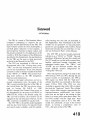
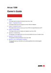
Foreword
(1976 Edition)
The TR3 is a result of The Standard Motor
Company's attempting to improve the appearance and the performance of the TR2. The
improvements consist of a more stylish grille, a
one-half gallon reduction in fuel capacity, a
ten-horsepower increase in engine output, and
the greater potential for the application of the
overdrive. With the exception of the differences
described in this Supplement, the specifications
for the T R 3 are the same as those previously
set forth in this Manual for the TR2.
The TR3 was introduced in 1956 and was
discontinued after 1961. During these years,
"TR3" was the only designation used for the
cars by the manufacturer. It has since become
common to refer to the later models of the TR3
as the "TR3A" or "TR3B". The custom of adding letter suffixes to the TR3 designation
deserves some explanation.
Owing to the larger carburetors and an increased compression ratio, the engine of the
TR3 is more powerful than that of the TR2. In
the United States, the TR3 was always advertised as having 100 B.H.P. at 5,000
R.P.M.-though the General Data given in
this Supplement list the power as 95 B.H.P. at
4,800 R.P.M., which is the British rating. On
TR3 cars with overdrive, the overdrive can be
engaged on the top three gears whereas, on the
TR2, overdrive is available on top gear only.
The 1957 TR3 is the earliest model equipped
with the disc front brakes, the separate brake
and clutch master cylinders, and the tapered-
roller bearing rear axle that are described in
this Supplement. Also introduced on the 1957
models was an optional 4.1: 1 ring and pinion
gearset for cars equipped with overdrive. Road
speed and ratio data for cars with the 4.1: 1 rear
axle can be found in Part 1 of this Manual.
The 1958 TR3 is the first model commonly
referred to as a "TR3A" or "TR3B". The only
significant differences between this model and
the 1957 model are a wider grille, external door
handles, reinforced bumper overriders, and
redesigned bucket seats. The "TR3A" and
"TR3B" are not different models; they are
simply different people's designations for
"wide grille" TR3 cars.
Only one important change was made to the
TR3 between 1959 and 1961. During the last
several months of manufacture, the 1991-cc
TR3 engine was fitted with the "high port"
cylinder head that was continued on the subsequent 2138-cc TR4. (The TR4 was also
available on special order with a 1991-cc engine
that had the "high port" head.) This cylinder
head, which offers superior opportunities for
high-performance modification, has intake
ports that are set high in the casting so that
there is no water jacket space above them. The
first TR3 models with the "high port" head
had a compression ratio of 8.5:l. The 1961
model was advertised, at least in the United
States, as having a compression ratio of
9.0: l-the same as that of the TR4.
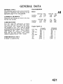
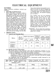
GENERAL DATA
The information given in this section should be
studied in conjunction wi
appropriate pages of the m
CAMSHAFT BEARINGS
Vandervell shell bearings are fitted to the 2nd,
3rd and rear journals.
CARBURETTORS
Two S.U. Type H6 carburettors are fitted.
The early TR3 cars were fitted with carburettors having c c T D " needles, but this needle
was changed to type " T E " early in normal
production and was, at Engine No. TS.l0037E,
superseded by type cc SM ". Where replacement needles are required for carburettors
fitted with the early needles, both needles
should be replaced by the " SM " needle.
PERFO-CE
DATA
95 B.H.P. at 4,800 R.P.M.
TRANSMISSION
Ratios
O/D Top Top
1.00
.82
Gearbox
Overall
3.03
3.7
Gearbox
Overall
O/D 2nd 2nd
1.64
2.00
6.07
7.4
Engine Speed at
10 m.p.h.
O/D Top
410 R.P.M.
Top
500
O/D 3rd
540 ,,
3rd
660 9,
O/D 2nd
820 ,,
2nd
1,000 YY
1st
1,680 Y¶
Rev.
2,130 9,
¶,
O/D 3rd 3rd
1.08
1.325
4.02
4.9
1st
3.38
12.5
Rev.
4.28
15.8
10 km.p.h.
245 R.P.M.
310 ¶Y
340
410 ¶Y
510
620 9,
1,050
1,325
¶¶
¶¶
¶¶
¶¶
I
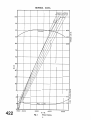
GENERAL DATA
Fig.
I
Power Curve.
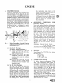
ENGIN
I.
CYLPNDER BLOCK
Vandervell replaceable shell bearings have
been introduced for the 2nd, 3rd and rear
camshaft journals. These pe manufactured
to very fine limits, and whilsrcertain fitting
precautions must be observed, line boring
of the assembled bearings is unnecessary.
Removal of the rear bearing will necessitate
the removal of the sealing disc behind it,
which, in turn, will require the removal of
the gearbox, clutch and flywheel. The tool
illustrated in Fig. 1 is designed to assist
in the removal and replacement of the
bearings.
Fig. r.
this instruction may. result in the
bearing becoming distorted when the
locating screw is tightened.
Fit a plain steel washer of h"thickness
(1.558 mm.) between the head of each
locating screw and the cylinder block.
Refit or replace the camshaft sealing
&sc if necessary.
2.
ALUMINIUM PEDESTALS FOR
ROCKER SHAFT
New rocker pedestal brackets of aluminium
alIoy were incorporated in normal production at Engine No. TS.12564E. The new
metal, by reason of its higher degree of
expansion when hot, enables the same
rocker clearances to be used for exhaust
valves as were previously applied only to
the inlets. This reduction in the exhaust
valve clearances has the advantage of
reducing " tappet " noise when the engine
is cold without any sacrifice of performance.
Where it is desired to fit the new pedestal
brackets, these should be fitted as a
complete set, the part numbers being as
follows :-Aluminium Pedestal Bracket (Plain) -3 off -Part No. l 12546
Aluminium Pedestal Bracket (Drilled)l off -Part No. 112545
3.
PISTONS
From Engine No. TS.9731E, the pistons
are fitted with :l Plain ring.
1 Taper ring.
1 Oil scraper ring.
4.
COMBUSTION HEAD
T o further improve performance, " High
Port" type combustion heads where incorporated in production at Engine No.
TS.9350E. In countries where high octane
fuel is unobtainable, the compression ratio
may be lowered to 7.511 by the use of a
compression plate, Part No. 200906. This
plate must be used in conjunction with a
steel " Corrojoint " gasket, Part No. 202775
in addition to the normal gasket.
When using thls low compression plate it
wdl also be necessary to use Champion L. 10
sparking plugs gapped to 0.025" and special
push rods, Part No. 114048.
Fitting Intermediate Camshaft Bearing
using Churchill Multipurpose Tool No. 32
with Adaptors §.p-I.
( 4 Camshaft Bear
T o remove, proceed as follows :(i) Using a suitable tool, drift the
seahng disc out of the rear camshaft bearing housing.
(ii) Unscrew and remove the three
shouldered setscrews and plain
washers which retain the bearings
in position.
(z)
Assemble the extracting tool and
cylinder block
withdraw each
bearing in turn.
(W To Fit New Bearings
See Fig. 1 and observe the following:
The oil feed holes must be correctly
aligned and when drawing the bearings
into position all possible precautions
should be taken to ensure that these
do not turn and so misalign the holes.
Ensure also that the locating hole in
each bearing is centrally &sposed in
the tapped hole which accommodates
the locating screw. Failure to observe
BI
ENGINE
5.
ENGINE OIL FILTER
In order to give the maxhum protection
to the engine when subjected to high speed
or rally conditions, a new filter of the
" full flow " type has been introduced on
the TR3 models. This type of filter ensures
that all the oil in circulation passes through
the filtration system.
The " full flow " type of filter was introduced into normal manufacture at Engine
No. TS.l2650E., part numbers affected
by this change berng as follows :Oil filter assembly, Part No. 301994, is
replaced by Part No. 203271.
The replacement Element, Part No. 101963,
remains the same for both types of filter.
The oil pressure on the " full flow " type
of filter remains at 70 Ibs. per sq. in. with
an oil temperature of 70°C. at an engine
speed of 2,000 r.p.m.
The new filter assembly can be fitted if
desired to an engine prior to TS.12650E.
6.
SUMP
A special cast aluminium sump, Part No.
301318, and tray, Part No. 201984, are
available as optional extras.
Fig.
2
Oil cleaner " ffullflow " type.
CLUTCH D
N PLATE ASSEMBLY
An improved clutch driven plate incorporating a Belleville washer friction centre was
fitted after Engine No. TS.7830E. (TR2).
The new driven plate can be recognised by
four small tongues (or tabs) protruding
through the spring retaining plates adjacent
to the longer side of the splined hub and by
the colour of the six cushioning springs,
white and light green.
HYDRAULIC OPERATING
,MECHANISM
This is described under " Girling Brakes
and Hydraulic Clutch " in the " Brake "
supplement.
A new rear axle assembly, Part No. 302177,
bearing the Serial NO.-i3511, was introduced at Commission No.
on all subsequent cars.
The major differences inc
new axle include new half shaft and hub
assemblies, a thrust button mounted on the
differential cross-pin an
roller hub bearings, as
The sectioned insert views indicate the axle
arrangement for cars prior to this change.
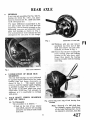
Extraction of rear hub.
Fig.
fii)Withdraw sdit asin and remove
castellated &t from end of half
shaft and remove rear hub with
extractor, as shown in Fig. 3.
crews securing the
\
I
Rear
from
Fig. 5
Removing hub bearing inner ring.
Fig. 6 Fitting hub bearing inner ring to axle shaft.
brake fluid pipe and the handbrake attachments must first be
disconnected and the backing
plate subsequently removed.
(iv) Extract the bearing outer ring
from the housing, as shown in
Fig. 4, after first tapping out the
oil seal which should be renewed
during re-assembly.
(v) Withdraw the axle shaft and inner
bearing ring. After first removing
the driving key, the bearing inner
ring is then removed by using the
extractor, as shown in Fig. 5.
(b) Inspection
Inspect bearing for looseness and
roughness ; the axle shaft for cracks
and worn splines ; the hub for loose
wheel studs and worn keyway. Replace all parts which are excessively
worn or defective in any way.
Note.-When
inspecting rear axle hub
bearings, apply as much load as possible by hand, as this enables noise and
roughness to be more readily detected.
(c) To Re-assemble
Continue as follows :(i) Using a special tool, drive the hub
bearing inner ring on to the axle
shaft, as shown in Fig. 6, and
refit key.
Fig. y
Fitting oil seal into bearing housing.
Fig. 8
Fitting oil seal into axle sleeve.
(ii) Draw the bearing outer ring into
the housing by using the same tool
as shown in Fig. 4, and install a
new oil seal (Fig. 7).
(iii) Exercising care to avoid damage
to the fabric face of the seal,
thread the assembled bearing
housing on to the shaft and refit
REAR AXLE
hub, plain washer and castellated
nut, t~ghtening this to a torque
of 125-145 lbs. ft. (17.29-19.71 kg.
metres) and securing it with a
split pin.
(iv) Examine the inner oil seal and,
if a replacement is necessary,
proceed as shown in Fig. 8. Oil
seal renewal is recommended in
all cases of axle overhaul.
(v) Replace the original shim pack
over the spigoted portion of the
axle sleeve, followed by the brake
backing plate.
(vi) Again exercising care in the case
of the inner oil seal, thread the
assembled axle shaft through the
seal and into the axle casing: After
locating the shaft splines in those
of the sun wheel, secure the
bearing housing by inserting and
tightening six setscrews with lockplates.
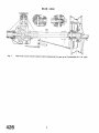
Fig. ro Showing position of differential cross-pin in
relation to thrust block.
towards and away from the axle casing.
T h e dial indicator will then record the
axle shaft end-float.
Adjustment is effected by adding to,
or subtracting from the shim pack
interposed between the axle sleeve
flange and the brake backing plate,
thus increasing or decreasing respectively the axle shaft end-float.
Important. -In addition to the existence of the specified end-float, it
is important that the thrust block
which separates the inner extremities of the two axle shafts,
should have a clearance on the
cross-pin, as shown in Fig. 10.
T o ensure centralization of the
thrust block with the cross-pin,
the shim packs behind both backing plates will be approximately
of equal thickness.
(vii) Replace brake drum, road wheel
and, before removing the lifting
jack, it is essential to grease the
hub bearing.
Fig. 9
Checking axle shaft end float.
M l A L AND PINION
Axle Shaft End-Float
T h e specified axle shaft end-float is
0.004"-0.006" (0.102-0.152 mm.).
This can be checked by mounting a
dial indicator on the backing plate, as
shown in Fig. 9, then moving the hub
Except for the addition of a thrust block
(item 15, Fig. 13), the crown wheel and
pinion assemblies remain the same as fitted
to the previous axle. Therefore, instructions for the servicing and adjustment of
these assemblies are unaltered.
1
REAR AXLE
5.
HIGH SPEED AND COMPETITION
WORK
(a) Rear Axle Assembly-ratio 4.111
A rear axle of the above ratio is
available for high speed and competition work but is only suitable for
cars fitted with Overdrive. The
installation and servicing procedure is
the same as for standard ratio axles.
Crown wheel
Part No. 202579
(41 teeth)
Part No. 202580
Pinion (10 teeth)
Complete axle assembly (for wire
wheels)
Part No. 505179
(for disc wheels)
Part No. 503930
Speedometer
The following special ratio speedometers are necessary when using 4.111
axles :Speedo - Kilo.
Part No. 113632
Part No. 113631
Speedo - Mile
(c) Centre Lock Adaptors
(Wire Wheel)
These splined hub extensions are
attached to the hubs by shorter studs
than normally used for disc wheels.
Figs 11. and 12 show the extensions
being fitted and the existing studs
sawn-off flush with the outside of the
wheel nuts.
Hub Extension
(L H ) Part No 202447
(R.H.) Part No. 202446
Knock-off Wheel Nut
(L.H.) Part No. 107949
(R.H.) Part No. 107948
Fig.
11
Fitting splined hub extension to normal hub.
Fig.
12
Reducing length of studs to enable wire
wheels to be fitted.
NOTATION F O R EXPLODED ARRANGEMENT OF REAR AXLE (Fig. 13)
Ref.
No.
1
2
3
4
5
6
7
8
9
10
11
12
13
14
15
16
17
Description
Axle casing assembly.
Bearing cap setscrew.
Spring washer.
Axle case breather.
Fibre washer.
Drain plug.
Differential bearing.
Adjusting shims for (7).
Differential casing.
Differential sun g'ear.
Thrust washer for (10).
Differential planet gear.
Thrust washer for (12).
Cross pin.
Thrust block.
Lock pin for securing (14).
Crown wheel and pinion.
Ref.
No.
Description
18 Crown wheel securing bolt.
19 Plain washer for (18).
20 Three hole lockplate for (18).
21 Two hole lockplate for (18).
22 Pinion head bearing.
23 Adjusting shims for (22).
24 Bearing spacer.
25 Pinion tail bearing.
26 Adjusting shims for (25).
27 Pinion shaft oil seal.
28 Pinion driving flange.
29 Driving flange securing nut.
30 Plain washer for (29).
31 Split pin for (29).
32 Rear cover.
33 Joint washer fox (32).
34 Oil filler plug.
Ref.
No.
35
36
37
38
39
40
41
42
43
44
45
46
47
48
49
50
51
Description
Fibre washer for (34).
Axle half shaft.
Rear hub bearing.
Hub bearing housing.
Oil seal for hub bearing housing.
Adjusting shims for hub bearing.
Lockplate.
Setscrew for securing housing.
Hub.
Road wheel attachment stud.
Hub driving key.
Hub securing nut.
Plain washer for (46).
Split pin for (46).
Cover plate securing screw.
Spring washer for (49).
Axle tube oil seal.
REAR AXLE
Arrangement of Axle Components.
The following four instructions supersede
the operations X and xii on page 12
manual Front Suspension
These bearings supersede the rubber bushes and
were introduced k t o production at car Commission No. TS.9121.
They are as fo
Nylon bearing. 4 off. Pressed into each
wishbone arm.
Steel bush. 4 Q
Sealing rings.
e d g e of n y l o n
washers.
Nylon washers. 8 off. Fitted each side of
wishbone arms.
(i) Fit the rubber sealing rings
nylon washers.
(G) Press the nylon bushe
ends of the wishbone
(i) Smear the f u l c m pin situated on
pper face of the chas
grease and feed on
bushes.
BODY
BODY SPECIFICATION
Provision is made for the installation of an
occasional bench seat in the luggage compartment immediately behind the driver
and passenger seats.
7.
(a) Slide the joint plates on to the ends of
any one moulding.
(b) Position five stud plates in the upper
half of the beading and six in the lower
half at intervals to align with the holes
in the air intake periphery.
REVEAL MOULDING AND GRILLE
A chromium plated moulding is fitted to
the front rim of the air intake with a grille
mounted immediately behind.
(c) Attach the two halves of the reveal
mouldings to the air intake with nuts
and lock washers.
STAINLESS STEEL WING BEADING
The stainless steel wing beadings are
positioned between the front and rear
wings and the body of the car.
(d) Slide the joint plates from one moulding to the other and position in such a
manner that the joint is covered.
(e) Feed the grille in, top side first, and
settle the extremities of the vertical
struts adjacent to the reveal moulding
already installed.
PASSENGER SEAT
A folding squab seat is now fitted to allow
easier access to the luggage space behind
or to the occasional seat if the car is so
fitted.
OCCASIONAL REAR SEAT
These seats are an optional extra on the
TR3 models. Provision is made for the
installation of this seat in each car.
TO REMOVE REVEAL MOULDING
AND GRILLE
Withdraw the self-tapping screw from
each end of two horizontal grdle bars.
Ease the upper portion of the grille
into the air intake and withdraw the
assembly when it is inclined approximately 30".
TO REFIT REVEAL MOULDING
AND GRILLE
(f) Secure the grille by four self-tapping
screws one at each end of two of the
horizontal bars.
8.
TO REMOVE OR FIT WING BEADING
This is effected by removing or fitting the
front and rear wings as described on page 4
of the Body Section in the main portion of
the Manual.
9.
TO REMOVE PASSENGER SEAT
SQUAB
(a) Remove the cushion from the seat pan.
---
(b) Remove the two domed nuts at the
base of the seat squab.
\
Slide the moulding joint plates to one
side to expose the joint in the mouldings.
Remove the nuts and lock washers
from the stud plates securing the
mouldings to the air intake and withdraw the two half mouldings. Access
to these nuts entail working behind
the front cowling.
The stud plates can be withdrawn by
sliding them to the end of each half
moulding.
,
(c) Spring the squab from the seat pan.
10.
TO FIT PASSENGER SEAT SQUAB
(a) Position the seat squab on the seat
pan studs and attach with the dome
nuts.
(b) Fit the back of the seat cushion under
the spring clip at the rear of the seat
pan and settle cushion into position.
NI
BOD
11.
TO
OCCASIONAL SEATS
(a) Slide the driver and passenger seats
forward to their fullest extent.
(e) Position the occasional seat behind the
driver and passenger seats and secure
with four bolts removed during the
previous operations.
(b) Lift up the carpet at the rear of the
two seats and remove the two bolts
and washers so exposed.
(c) Make two small holes in the carpet to
gn with the tappings in the floor
assembly.
(d) Withdraw the two chrome headed
bolts and washers from the trim at the
rear of the passenger compartment.
12.
TO WEMOV OCCASIONAL SEAT
(a) Withdraw the four attachment bolts
and plain washers.
(b) Remove the seat from the rear of the
passenger compartment.
( c ) Return the bolts and plain washers to
their tappings for safe keeping.
BODY
Description
The " Hard Top " is of presse steel construction, incorporating channel sections which are
spot welded to the main panel. These channels
By stiffen the as mbly and also
ate the front an rear mounting
brackets. The sides of the main panel are folded
to form a "U" section which further strengthens
Detail
No.
500229
502233
Description
No.
off.
Round headed %K screw (
channel)
l0
Counters
screw (screen
l2
22
r TW2 cars, sli
BODY
2.
WINDSCREEN
TOP RAlL
WINDSCREEN
ATTACHMENT
BRACKET
PENCIL MARK
TRANSFERED
T O CAPPING
.
PROTECTION
/PLATE
SECURING
SCREW
BRIDGE PIECE
PENCIL MARK
OPPOSITE CE
O F BRIDGE P
REMOVE HOOD WEBBING BY
REMOVING 2 FLAT HEADED
SCREWS AND 2 HOOD
FASTENER SCREWS
Fig.
I
Marking and fitting Rear Cappings.
(c) Unscrew and remove the four countersunk screws securing the hood frame
to the body, and then lift the frame
out of the body.
(d) Detach the five cappings from the
elbow rail after removing the P.K.
securing screws. Remove the two
wood blocks from the elbow rail.
(Fig. 2.)
H
TOP PREPARATION
(a) Loosely assemble the three windscreen
attachment brackets on the cc Hard
Top " front rail.
(b) If not already fitted, insert the three
shorter angle brackets through slots
in the stiffener rail at the rear of the
"Hard Top", and a longer angle
bracket at each side. Using short flat
headed screws and lockwashers, secure
the brackets in position. (Fig. 4.)
NOTE-It will be necessary to neatly cut
the trim fabric to allow entry of
the brackets into the slots in the
stiffener channel.
WINDSCREEN ATTACHMENT
BRACKETS-TO FIT
CAUTION-To guard against the possibility of damage to paintwork,
masking tape should be applied
to that part of the body which
will be in contact with the hard
top during fitting operations.
(a) Position the hard top on the car and
feed the assembled brackets under the
windscreen top rail.
'A
CENTRALISE HARDTOP
(e) Remove the millboard from the front
of the petrol tank after removing
the P.K. securing screws. (Fig. 2.)
REMOVE MILLBOARD
WINDSCREEN TOP
RAlL CLAMPED
BETWEEN HARD TOP
AND BRACKETS.
HOOD WEBBING
TEMPORARY SECU
HARD TOP BY TIGHTENING
THE SCREW BRACKET.
MARK POSITION OF HOLES.
HOLES IN THE ELBOW
RAlL ARE PR€ WILLED
ON ALL CARS AFTER
T S 6824
Fig.
2
$~~~~
yM
TOP FACE OF WINDSCREEN TOP RAIL.
'D'
Showing Cappings removed.
NOTE-The
P.K. screws securing the
bottom of the millboard can be
removed after lifting the rear of
the carpet.
Fig. p,b, c and d
Positioning " Hard Top " and
drilling Screen Rail.
BODY
Centralise the " Hard Top " over the
windscreen and temporarily secure by
tightening the three attachment
brackets. (Fig 3A.)
(c) Mark the position of the bridge pieces
on the elbow rail and identify them to
these positions. Release the " Hard
Top " at the windscreen and remove
from the car.
(b) Mark the position of the attachment
bracket holes on the underside of the
windscreen top rail (Fig 3B). Slacken
off the brackets then remove the Cc Hard
(d) Using a No. 11 drill, drill ten holes
through the markings on the elbow
rail.
(e) Remove the bridge pieces from the
cc Hard Top " and secure to the elbow
rail channel, using flat headed screws
which screw into tapping plates fed
into position under the channel. (Fig.
4.)
(c) Mark the top side of the screen exactly
in line with the markings previously
made on the underside (Fig. 3C).
Using a No. 11 drill, care
six holes from the above screen and
A" from the edge. (Fig. 3D.)
(d) Remove the windscreen attachment
brackets from the " Hard Top " and
finally secure to the underside of the
windscreen top rail by six chromium
plated screws and lock washers. (Fig.
1-1
4.
BRIDGE PIECES-TO F
(a) Loosely secure the five bridge pieces
to the angle brackets previously fitted
in the rear stiffener rail. (Fig. 4.)
(b) Reposition the "Hard Top " to the car
and secure to the three windscreen
attachment brackets.
The bridge
pieces will now be resting on the elbow
rail channel. (Fig. 4.)
5.
REAR CAPPINGS-TO FIT
(a) Opposite to the centre of each bridge
piece, scribe a line with a pencil on
the body protection tape. Attach the
cappings to the body, loosely securing
with the P.K. screws. (Fig. 1.)
(b) Over the cappings, extend the markings
previously scribed on the body. Remove the capping~ from the car.
Scribe the inside of the cappings
exactly in line with the marks on the
outside. (Fig. l.)
(c) Using a #" drill, drill the cappings at
the positions marked on the insides
and ensure that when drilled, the holes
are aligned with those in the bridge
pieces.
(d) Attach the millboard to the front of the
petrol tank and secure with P.K.
screws. Refit the cappings over the
bridge pieces and secure.
(e) Select the three narrow protection
cavs and vosition these on the rear
cabpings, -aligning the centre holes
with the threaded centres of the bridge
pieces. Drill the cappings through fie
protection caps and secure with P.K.
self tapping screws. The two larger
caps are fitted in a similar manner to
the side elbow rails. (Fig. 1.)
Fig. 4 Drilling the Elbcrw Rail and installing Bridge
Pieces.
NOTE : Drilling should only be necessary on Cars
prior to TS.683.
(f ) Fit four countersunk screws and chromium washers in the holes previously
used to accommodate the hood bracket
screws. Remove the protecting tape
from the body of the car.
NI
BODY
DRIP CHANNELS-TO
(See Figs. 5 and 6)
6.
FIT
DRIP CHANNEL
".
Fitting Rear Window and Waist Rubber.
Fig. 7
Fig. 5
Fitting lower part of Drip Channel.
After correctly shaping the ends of the
drip channels, position the channels and
draught rubbers " C " on the "Hard Top "
as dustrated and secure with the screws
" A " and " R ". (Fig. 6.)
Fig. 8
Fig. 6
7.
Fitting Screen Rubber.
Fitting Drip Channel and Draught Rubber.
SEALING RUBBERS-TO FIT
Using " Seelastik ", secure the rubber
mould " D " (Fig. 7) to the rear lower
edge, and the rubber section " E " (Fig. 8)
to the front top edge of the CcHardTop ".
8.
W A R D TOP-TO FIT
Re-position the " Hard Top " on the body
and after loosely assembling the attachment bolts, progressively tighten them until
the cc Top " is finally secured.
BODY
9.
REAR WINDOW LIGHT-TO
m
(See Fig. 7)
Fit the rubber moulding around the glass
with the filler sectionpositioned towards the
rear of the car. Offer the glass with the
rubber attached, to the aperture in the
<'HardTop" and with the help of an assistant
manipulate the inner rubber 1 . i ~into vosition. * Using a special tool (see ~ i i 7)
.
finally secure the glass by feeding the filler
strip into position. With the aid of a
" Seelastik gun ",complete the installation
by forcing Sealastik compound between the
<<HardTop " and the outer lip of the
glazing rubber to effect water sealing.
FUEL S
PETROL TANK
The petrol tank has been modified slightly
to accommodate the occasional seat, its
capacity is thereby reduced to 12 gallons.
7.
FLEXIBLE FUEL PIPES
A flexible fuel pipe connects the twin
carburettors and is integral with a short
feed line which is connected to the Bundy
tubing at a point adjacent to the thermostat
housing.
(b) Feed a fibre washer on to the banjo
bolt, followed by the banjo connection
and a second fibre washer, and then
attach to the rear carburettor and leave
fmger tight at this juncture.
(c) Repeat operation (a) and (b)with the
front carburettor.
CAlWUlWTTORS
$.U. H6 type carburettors are fitted to this
engine. This carburettor has a four-point
mounting but is similar in other respects
to the H4 used on the TR2, is identical in
operation and requires the same maintenance.
Carburettors fitted to early cars were
equipped with " T D " needles, while with
later cars " T E " needles were used, this
needle in turn was superseded by- type
cc §M " at Engine No. TS. lOO37E. When
needles are changed for any reason a pair
of type §M " should be fitted.
AIR CLEANERS
The air cleaners are similar to those fitted
to the TR2 apart from the off-set mountings.
(d) Holding the hexagon of the flexible
hose with a spanner, attach the union
nut of the rigid supply pipe and secure
to give a petrol tight joint.
(e) Adjust the position of the banjo con-
nections on the float chambers of the
twin carburettors so as to avoid any
strain, and tighten banjo bolts to give
a petrol tight joint.
(f) Start the engine and observe the he1
pipes for leaks.
8.
INLET MANIFOLD
This has been modified to accommodate
the four-point fixing H6 carburettor, and
manifolds fitted to engines after TS.9350E
have a larger bore to align with the enlarged
throat area of the high port combustion
head.
TO IPEMOVE
LE
L
HOSE ASSEMBLY
(a) Hold the hexagon of the flexible hose
assembly and disconnect the union
nut of the rigid pipe adjacent to the
thermostat housing.
(b) Withdraw the banjo bolt from one
carburettor, collecting the gauze filter
and retaining spring.
(c) Repeat operation (b) with the second
carburettor.
TO FIT FLEXIBLE FUEL HOSE
ASSEMBLY
(a) Position the filter assembly in the rear
carburettor float chamber, spring first.
CAlWUREl'TOR DETAILS
The instructions given for the H4 carburettor as fitted to the TR2 apply to the
H6 type apart from the four-point mountings. The jet needles at present used in
normal manufacture are of the "SM"
type, although with early releases of the
TR3 model the " T D " or T E " needle
was fitted.
The " T D " or T E " needles in both
carburettors should be replaced by type
" SM"
if damage or wear justifies the
exchange in either unit.
g.
AIR CL
RS
The air cleaners have off-set mounting and
must be positioned on the carburettor air
intake in such a manner that the off-set is
rearward.
10.
INLET MANIFOLD
The inlet manifold is removed and fitted as
those fitted to the TR2 engine.
PI
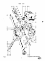
MASTER CYLINDERS
FLUID RESERVE TANK
COMPENSATOR
STOP LIGHT SWITCH
GREASE NIPPLE
SLAVE CYLINDER
ND BRAKE RATCHET
BEFORE SETTING HAND BRAKE CABLE
LOCK THE REAR SHOES UP IN THE
DRUMS AND APPLY HAND BRAKE
LEVER ONE NOTCH CABLE AND
WIRE ROPES SHOULD BE JUST TAUT
Fig.
Brake and Clutch layout
I
GlRLING BRAKES
ULIC
CLUTC
(From Chassis No. T S . q ~ o x )
The brakes on the front wheels are the
Girling Disc Brakes and on the rear are
Girling HL.3 Drum Brakes. M four
wheels are hydraulically operated by foot
pedal operation, directly coupled to a CV
master cylinder in which the hydraulic
pressure is originated. A supply tank
which provides fluid reserve for both brake
and clutch systems is installed to allow for
fluid replenishment.
An independent mechanical linkage (see
Fig. 6), actuated by a hand lever control,
operates the rear brakes by levers attached
to the wheel cylinder bodies, thus acting
as a hand or parking brake.
2.
FRONT B
S (Fig. I)
The front brakes are the 11" &a. Girling
Disc Brakes, which are extremely simple
in consmction, consisting of the 11" disc
Fig. z
Front Disc Brakes Assembly.
which is made from high quality cast iron
and cast iron calipers mounted to a support
bracket.
-SET
BOLTS
-RETAINING
PLATES
WASHER--.
LINING SEGMENTS
BUST COVER-
-DUST COVER
SEALING RING
PISTON
/
/
GASKET
Fig.
2
Due to the simplicity of these disc brakes
the only normal servicing which w d be
carried out by the owner or garage w d be
the replacement of worn lining segments,
seals and boots of the hydraulic caliper.
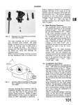
(a) Lining Segment Replacement
(Fig. 2)
Jack up the front of car and remove
road wheels. On the top of the caliper
body are two setscrews which secure the
segment retaining plates. The release
of these will enable the retaining plates
to be raised out of engagement with
the casting and swung through an arc
of 180". The segments are then fully
exposed and can be lifted out of the
&per.
Under no circumstances should attempts be made to reline worn segments
and these must be replaced by new
parts.
END PLUG
/
PLUG RETAINER
Exploded arrangement of Disc Brake Caliper Assembly.
In order to fit new segments the pistons
in the caliper bore should be pushed to
the bottom, and the new segments
placed into position. When the segments are positioned correctly, the
retaining plates should be replaced in
their original position and the setscrews
tightened down.
The replacement of segments is then
complete and bleeding is unnecessary,
but the foot pedal should be pumped
until a solid resistance is felt.
Jack down the front of the car and
road test.
(b) Caliper Cylinder Maintenance
To Replace the Rubber Seals
In order to replace the rubber " 0 "
rings or seals it is necessary to remove
the caliper assembly from the vehicle.
The brake segments should be removed in the manner described above.
Instead of pushing the pistons to the
bottom of the bore withdraw them
from the caliper body, taking great
care not to damage the bores. The
sealing rings may then be removed by
inserting a blunt tool under the seals
and prising out, talung care not to
damage the locating grooves. Examine the bores and pistons carefully
for any signs of abrasion or "scuffing."
No attempt should be made to remove
the end plug retainer, as this is screwed
in tightly by mechanical means.
It is important that in cleaning the
components no petrol, paraffin, trichlorethylene or mineral fluid of any
kind should be used. Clean with
methylated spirits and allow to vaporise, leaving the component clean and
dry.
After cleaning and examining, lubricate
the worlung surfaces of the bores and
piston with clean genuine Girling
Crimson Brake and Clutch Fluid.
the bore, taking great care not to
damage the polished surface. Push the
piston right home and then engage the
outer lip of the rubber boot into the
groove of piston.
The replacement of the lining segments
as described under the heading " Segment Replacement " will retain the
pistons in position.
Refit the caliper assembly to the support bracket by means of the two
securing bolts ensuring that the disc
passes between the two lining segments.
Re-connect the pressure hose and bleed
the brake, as described under " Bleeding the System."
a.
DISCS
T o ensure that the brake functions at
maximum efficiency a check should be
made to see that the disc runs truly
between the segments. The maximum
run-out permissible on the disc is .004".
(For instructions regarding wheel bearing
settings refer to page 7, Section G," in
the main part of this manual.) If excessive
run-out is present this wdl cause the
knocking back of the pistons which will
possibly cause judder.
If it is found that the discs have been
damaged in any way, which is extremely
unhkely, it will be necessary to remove the
discs from the car in order for them to be
('trued " up. Under no circumstances
should more than .060" be removed, with
the finish to be 32 micro ins. maximum
measured circumferentially and 50 micro
ins. measured radiallly.
3.
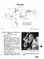
REAR BRAKES (Figs. 3 and 4)
Assembling
Fit new rubber seals into the grooves
of caliper cylinder bore. Locate the
rubber dust cover with the projecting
lip into the groove provided which is
the outer one of the cylinder bore.
Insert the piston, closed end first, into
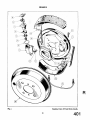
Fig* 3
Rear Drum Brake Assembly.
From the illustration it will be seen that
they are of the drum type with a wheel
cylinder and adjuster affixed to a backplate
supporting the two shoes which are held in
position by two return springs. The shoes,
which are hydraulically operated by the
Girling single acting wheel cylinder (incorporating lever handbrake mechanism),
are not fixed but are allowed to slide and
centralize. Lining wear is adjusted by a
Girling wedge type mechanical adjuster
common to both shoes. At the cylnder end,
the leading shoe is located in a slot in the
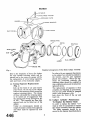
Details of Rear Brake Assembly.
g shoe rests in a slot
h d e r body. At the
adjuster end the shoe ends rest in slots in the
adjuster links. The shoes are supported by
platforms formed in the backplate, these
being held in position by two hold-down
springs fitted on each shoe with a peg passing
through a hole in the backplate.
The adjuster consists of an
housing with studs, which is spigoted and
secured firmly to the inside of the backplate
by nuts and spring washers.
The housing carries two oppose
the outer end slotted to take th
the inclined inner faces bearing on inclined
faces of fhe hardened steel W
of which is at right angles to
finished bore of a light alloy die cast wheel
cylinder body, whilst a slot, machined in
the opposite end of the body, serves to
carry the trailing shoe. The cylinder,
incorporating a bleed screw with rubber
cap, is attached to the back plate by spring
clips which allow it to slide laterally. The
handbrake lever pivots on, and projects at
right angles through the back plate.
brake is applied, the piston under
nce of the hydraulic pressure
moves the leading shoe and the body reacts
by sliding on the backplate to operate the
trading shoe.
The handbrake lever is pivoted in the
cylinder body and when operated, the lever
tip expands the leading shoe and the pivot
moves the cylinder body and with it the
forced apart and the fulcrum of the brake
shoe expanded.
moves in the highly
If it is found necessary to remove a
eel
r, the following
e sh
followed :-
(i) Jack up the vehicle, remove the
isconnect the rod
(3)Remove the brake d
Disconnect the
union from the
remove the rubber
rear of backplate.
(iii) By using a screwdriver, prise t
retaining plate
apart, then tap
from beneath
wheel cylinder.
e handbrake lever
from between t e backplate and
wheel cylinder.
(v) Remove the spring plate and
distance piece, and finally the
wheel cylinder from the backplate.
(b) Refitting the Rear
brake lever location. The two cranked
lips must also be away from the
backplate.
Insert the spring plate between the
distance piece and backplate, also with
open end away from handbrake lever
location and the two cranked lips away
from the backplate.
place handbrake lever. Locate the
aining plate between the distance
piston in place.
ii) Clean down the backplate, check
(iv) Check adjusters for easy
and turn back (anti-cloc
full " off" position.
necessary with Girlin
(v) Smear the shoe platforms and the
with Girling White
(vi) Fit the two new shoe return
springs to the new shoes (with
the shorter spring at the adjuster
end) from shoe to shoe and
oe web and backplate.
Locate one shoe in the adjuster
link and wheel cylinder piston
slots, then prise over the opposite
shoe into its relative p o s i h x
Remove rubber band. Insert the
hold down peg through hole in
backplate, and replace spring and
(vii) b make sure drums are cleaned and
free from grease, etc., then refit.
(viii) Adjust brakes.
(ix) Refit road wheels and jae
Note.-The
first shoe \has the lining
plate.
Fit the rubber dust cover. Attach the
assemblies.
(i) Jack up the car and remove road
wheels and brake d m s .
(ii) Remove the holding down springs
by turning the was
peg head. Lift one of the shoes out
ndbrake Set ting-refm to Fig. 1 .
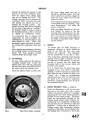
BRAKES
Release the handbrake and jack up the car.
Turn the square end of the adjuster on the
outside of each rear brake backplate in a
clockwise direction until a resistance is
felt, then slacken back two clicks, when the
drum should rotate freely.
Immediately after fitting replacement shoes
it is advisable to slacken one further click
to allow for possible lining expansion,
reverting to normal adjustment afterwards.
The front disc brakes are entirely selfadjusting. The rear brakes are adjusted
for lining wear at the brakes themselves,
and on no account should any alteration be
made to the hand brake cable for this purpose (Fig. l).
One common adjuster is provided for each
brake assembly. Adjustment of both rear
wheels is identical.
BOOT RETAINING BAND
JAW END.
VALVE SPACER
PLUNGER SEAL.
SPRING THIMBLE.
C.V. Girling Brake and Clutch Master Cylinder.
Fig. 5
CLUTCH HYDRAULIC OPERATING MECHANISM
5.
HYDRAULIC CLUTCH OPERATION
A slave cylinder mounted on the side of the
clutch housing is mechanically connected
to the clutch operating mechanism. This
assembly, by reason of its
nection, is actuated by a Girling C.V.
master cylinder to which the suspended
clutch pedal is coupled.
When pressure on the clutch pedal is
applied, the piston of the master cylinder
displaces the fluid in the cylinder which in
turn moves the piston of the slave cylinder,
pushing against the lever of the clutch
thrust race.
(a) The CV Master Cylinder (For Brake
and Clutch, Fig. 5)
This is the Girling CV Type, which
consists of an alloy body with a
polished finished bore. The inner
assembly is made up of the push rod,
dished washer, circlip, plunger and
seal, plunger seal, spring thimble,
plunger return spring, valve spacer,
spring washer, valve stem and valve
seal. The open end of the cylinder is
protected by a rubber dust cover.
Disrnant
Disconnect the pressu
unions from the cvli
the securing bolts Hnd devis pin from
jaw end. Pull back
cover and remove the circ
pair of long nosed pliers. T h
and dished washer can th
assembly well with Gir
clutch fluid, and insert
assembly into the bore of the cylinder,
valve end first, easing the
e bore. Repllace
Qshed side of washer under
r i d head into the cylinder,
followed by the circlip which engages
oove machined in the cylinder
removed the pl
tached, W& then
the plunger assembly complete. The
assembly ca
l i h g the
shouldered end of the plunger. Ease
the pressure seal off the plunger and
remove back seal. Depress the plunger
return spring allowing the valve stem
slide through the elongated hole of
e thimble, thus releasing tension of
spring.
Remove thimble, spring and valve
complete. Detach the valve spacer,
taking care of the spacer spring washer
which is located under the valve head.
Remove the seal from the valve head..
Examine all parts, especially the seal,
for wear or distortion, and replace with
new parts where necessary.
Replace the rubber dust cover, refit
the cylinder to the chassis and bleed
the system.
Asse
Replace the valve seal so that the flat
side is correctly seated on the valve
head. The spring washer should then
be located with dome side against the
underside of the valve head, and held
in position by the valve S
legs of which face towards
seal. Replace the plunger return spring
centrally on the spacer, insert the
is of simple construeThe slave
tion, consi
alloy body, piston with
seal, piston stop, spring and bleed screw,
the open end of the cylinder being protected
r dust cover. The cylinder is
the clutch housing by a flange
Remove the rubber dust cap from
stop, then, by using an air h e , blow
Assembling
plunger into the thimble until the
bolts, and screw in the pipe union.
SPRING
l
SEAL
I
PISTON
I
PISTONSTOP
/
BLEED VALVE
DUST COVER
Fig.
Bleeding
Remove the bleed screw dust cap, open
the bleed screw approximately threequarters turn and attach a tube, hmersing the open end into a clean
receptacle containing a little GirlBng
Crimson Brake and Clutch Fluid. Fill
the master cylinder reservoir with
genuine Girling Crhson Brake and
Clutch Fluid, and by using slow full
strokes pump the pedal until the fluid
entering the container is free from air
bubbles. On a down stroke of the
pedal, nip up the bleed screw, remove
the bleed tube and replace the dust cap.
After bleeding, top up the reservoir to
its correct level of approximately three-
(a) Replenishment of Hydraulic Fluid
for both Brake and Clutch Systems
Inspect the reservoir at regular intervals
and maintain at about threequarters
by the addition of Girling Crimson
Brake and Clutch Fluid.
Great care should be exercised when
adding brake fluid to prevent I r t or
foreign matter entering the system.
Important.-Serious
consequences may
result from the use of incorrect fluids,
and on no account should any but
Girling Crhson Brake and Clutch
Fluid be used. This fluid has been
PUSH ROD
Clutch Slave Cylinder.
specially prepared and is unaffected
by high temperatures or freezing.
p the system with any
g the Hydraulic System
Bleeding is necessary any time a
portion of the hydraulic system has
been disconnected, or i
level of
the brake fluid has been
ed to fan
so low that air has entered the master
er.
all the hydraulic connections
secure and the reservoir topped up
with fluid, remove e rubber cap from
the L.H. rear blee nipple and fit the
bleed tube over the bleed nipple,
immersing the fret: end of the tube in a
clean jar containing a little Girling
Brake and Clutch Fluid.
Unscrew the bleed nipple about threequarters of a turn and then operate
the brake pedal with slow, full strokes
until the fluid entering the jar is
completely free of air bubbles.
Then during a down stroke of the
brake pedal, tighten the bleed screw
sdiciently to seat, remove bleed tube
and replace the bleed nipple dust cap.
Under no circumstances must excessive force be used when tightening the bleed screw.
This process must now be repeated
for each bleed screw at each of the
three remaining brakes finishing at the
that has just been
stem for topping U
reservoir, since this fluid may be to
ated.
ess is essential when
dealing with any part of the hydraulic
system, and especially so where the
brake fluid is concerned. Dirty fluid
must never be added to the system.
wheel nearest the master cylinder.
Always keep a careful check on the
reservoir during bleeding, since it is
most important that a
level is
maintained. Should air reach the
master cylinder from the reservoir,
the whole operation of bleeding must
be repeated.
After bleeding, top up the reservoir to
its correct level of approximately threequarters full.
GE
VICE ON
The following precautions should be studie carefully and observed punctiliously by
all concerned.
Essential Precautions
Always Exercise extreme cleanliness when
dealing with any part of the
hydraulic system.
Never Handle rubber seals or internal
hydraulics parts with greasy hands
or greasy rags.
Always Use Girling Crimson Brake and
Clutch Fluid from sealed quart
tins.
Never Use fluid from a container that
has been cleaned with petrol,
paraffin or trichlorethylene.
Never Put dirty fluid i n t ~the reservoir,
nor that which has been bled
from the system.
ways Use clean Girling Brake and
Clutch Fluid or alcohol for cleaning internal parts of hydraulic
system.
Never Allow petrol, parafiin or trichlorethylene to contact these
parts.
Always Examine all s d s carefdy when
overhauling hydraulics cylinders
and replace with genuine G i r h g
spares, any which show the least
sign of wear or damage.
N w a y s Take care not to scratch the
highly finished surfaces of cylinder
bores and pistons.
ways Use WAKEFIELD / GIRLING
Rubber Grease No. 3 (Red) for
packing rubber boots, dust covers
and lubricating parts likely to
contact any rubber compnents.
Never
Use Girling White Brake Gr
or other grease for this purpose.
Always
ace all seals, hoses and
new ones if it is su
that incorrect fluids have
used or the system contarninat
with mineral oil or grease. Drain
off the fluid, thoroughly wash all
metal parts and flush out all pi ,
etc., with alcohol or clean Gir g
Crimson Brake and Clutch Fluid
Use anythmg else for this purpose.
C
Never
Alwavs Use a articular container (reserved f& this p
ing the system,
tain in a clean con&aion.
-
Never
Use a receptacle which
cleaned with petrol, p
trichlorethylene.
ways Remember that your safety and
the safety of others m% depend
on the observance of ese D*
cautions at all times.
I
XHAUST
E
UST SYSTEM
The exhaust system is unchanged from the
TR2 apart from the new manifold gasket
fitted to the enlarged port combustion
head after engine number TS.9350E.
Notes on the way this file was
produced (and why)
Books on the repair and maintenance of the old Triumphs
are becoming more and more difficult to locate; many
have been out of print for years or even decades, and
good examples are increasingly hard to find at reasonable
prices.
Then, too, there are all the people like me who have a
copy of a valuable reference book, but in rather forlorn
condition. Mine happened to be sitting in the trunk of an
immobile 1957 TR3 for a decade before I purchased the
car (and the manual), and thus came to me reeking of
gasoline and with a binding which no longer bound the
book together, but rather produced a crumbly mess any
time I turned a page.
So I set about to produce an electronic copy of this, the
Robert Bentley manual for the TR2 and TR3 cars, in order
to have for myself a copy which I could keep in the garage
and use without worrying that it might be ruined (if it
became soaked with gearbox oil, I could just print another!). The project took much longer than I expected, but
the results are worth it.
I am providing this document so that others, like myself,
can have a copy of this most valuable book to use in their
shop or to keep in their boot and thus preserve their original for some time to come. I suspect that the publishers
of this book might not be terribly happy about the project
I’ve completed, but since they’ve had the book out of print
for nearly a quarter century, I don’t think I’m cutting in to
their profits in any way. I am not realizing any sort of profit on this myself. Nevertheless, I make the following disclaimer: you should really only be using this electronic
copy as a backup to a legitimately-owned printed copy; if
you use this electronic copy and don’t own the real book,
you assume all responsibility for any copyright violation
which may have occurred.
That having been said -- I hope that this document provides a valuable service to the Triumph community, and
that you find it useful and helpful in the restoration and
care of your own Triumph automobile. I also hope to continue this type of operation with other books and documents, though my free time is at a premium right now
(whose isn’t?).
And now for some notes on the use of this particular file:
I have not yet gone to the trouble of performing OCR
(optical character recognition) on the book; that’s more
time-intensive and indeed computer-intensive than I can
deal with right now. The proof-reading alone would kill me
(and it would have to proof-read -- imagine if the software
screwed up a torque settings chart, for example!).
Right now, each and every page (except for this one) is a
large, black-and-white graphic. You should be able to
print this to just about any sort of printer, but you will get
the best results on a PostScript-capable laser printer that
operates at 600 dpi (dots per inch) or better.
The printing will be slow, however, as each page is a relatively good size (about 3.7 MB). I found that a 600-dpi
B&W scan gave me outstanding results when copying the
text and illustrations, and also reproduced the photographs acceptably well. This would not be the case with
many documents, but given the very high contrast of the
pictures in the original manual, and the relatively coarse
line screen, it worked out rather well.
If you’re interested in the details of the production of this
file, I used a G3-upgraded PowerMacintosh 8500 computer, an Agfa SnapScan 1212U scanner (a relatively cheap
model, but of acceptable quality), Agfa’s own FotoLook
scanning software, Adobe Photoshop 5.5 for some quickand-dirty image retouching, and Adobe Acrobat 4.0 to convert the pages from EPS to PDF. Finally, because each
and every page was a separate document, I used
AppleScript, a programming language included with the
Macintosh operating system, to combine all 455 pages
into a single document.
Each scanned page was 3.7 MB in size, and all of the
pages together weighed in at over 1.6 gigabytes of data.
It took just over 4.5 hours to “distill” the pages into PDF
files.
I chose the PDF format because it can be opened, viewed
and printed on many different computing platforms, from
Windows to Mac to Unix to Linux (and I think even the
Amiga).
Enjoy!