1
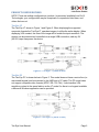
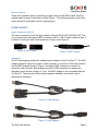
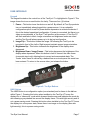
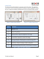
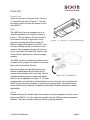
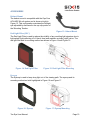
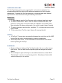
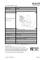
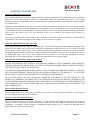
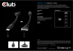
Tac-Eye® Display System
User Manual
THIS PAGE IS INTENTIONALLY LEFT BLANK
Tac-Eye User Manual
Page 2
Table of Contents
Table of Contents .................................................................................................................. 3
PRODUCT SUMMARY............................................................................................................. 4
FEATURE SET ......................................................................................................................... 4
PRODUCT CONFIGURATIONS ................................................................................................. 5
Tac-Eye LT ......................................................................................................................................5
Tac-Eye PC .....................................................................................................................................5
Button Option................................................................................................................................6
INTERCONNECT ..................................................................................................................... 6
Input Connector (QDC) ...................................................................................................................6
Adapters ........................................................................................................................................6
USER INTERFACE.................................................................................................................... 7
Keypad ..........................................................................................................................................7
HMD Button ..................................................................................................................................7
Control Panel .................................................................................................................................8
MOUNTING ........................................................................................................................... 9
Control Box....................................................................................................................................9
HMD ..............................................................................................................................................9
Cables............................................................................................................................................9
ACCESSORIES ....................................................................................................................... 10
Helmet Mount .............................................................................................................................10
Red Light Filter (RLF) ....................................................................................................................10
Eyecup.........................................................................................................................................10
Tac-Eye Handle ............................................................................................................................11
VGA Mouse..................................................................................................................................11
CLEANING AND CARE ........................................................................................................... 12
SAFETY ................................................................................................................................ 12
WARNINGS .......................................................................................................................... 12
TROUBLESHOOTING ............................................................................................................ 13
Problems and Solutions................................................................................................................13
Technical Support ........................................................................................................................13
SYSTEM SPECIFICATIONS ..................................................................................................... 14
REGULATORY ...................................................................................................................... 14
WARRANTY INFORMATION ................................................................................................. 15
CONTACT INFORMATION ..................................................................................................... 16
Tac-Eye User Manual
Page 3
PRODUCT SUMMARY
The Tac-Eye 2.0 is a display system for non-standard environments. Head worn and
hands free, it replaces a direct-view display while enhancing the capabilities of the user.
The system is much smaller and lighter than a traditional monitor, and consumes much
less power. It allows the user to maintain light discipline (no light signature from user)
and can be interfaced electrically and mechanically to a variety of models inherently, or
by utilizing the available accessories.
Its high-contrast SVGA display is perfect for displaying images from an Ultra Mobile PC,
unmanned sensors, or any other video source. Simple controls allow the operator to
optimize the display to their conditions, with little to no training required.
The Tac-Eye 2.0 Display System was designed to give the user access to mission
critical data. The head mounted display (HMD) was designed to plug directly into
computer systems, FLIR imagers, camera systems, thermal weapons sights, or remote
video sensors.
FEATURE SET
Figure 1: Tac-Eye LT Feature Set
Tac-Eye User Manual
Page 4
PRODUCT CONFIGURATIONS
NOTE: There are multiple configurations (product / accessories) available from Six15
Technologies; your configuration may be comprised of components listed here, and
others that are not
Tac-Eye LT
The Tac-Eye LT shown in Figure 1 and Figure 2. When displaying the supported
composite formats the Tac-Eye LT upscales imagery to utilize the entire display. When
displaying VGA content, the size of the image will be match the input resolution. The
system can be powered and controlled via a single USB connection, and any 5V
(±0.25V) input can power the device.
Figure 2: Tac-Eye LT (units in mm)
Tac-Eye PC
The Tac-Eye PC is shown below in Figure 3. This model does not have a control box (or
associated keypad) and is minimized to the HMD and a 19” cable. The PC model does
not support composite video formats (NTSC, RS-179, PAL). It also handles VGA
resolution content in the same fashion as the LT model. As there is no keypad available,
a Microsoft Windows application can be provided.
Figure 3: Tac-Eye PC (units in mm)
Tac-Eye User Manual
Page 5
Button Option
There is an available option of providing a single button on the HMD of both Tac-Eye
models which is shown in the balloon within Figure 1. The button provides a local video
mute function for immediate control of light security.
INTERCONNECT
Input Connector (QDC)
The input connector of both Tac-Eye models is Glenair PN 804-001-06ZNU8-13G. This
is a push-pull quick disconnect (QDC) connector with 10-12lb of mated retention force, it
is shown in both open and closed positions in Figure 4 and Figure 5.
Figure 4: QDC Open
Figure 5: QDC Closed
Adapters
Six15 Technologies provides two standard input adapters for the Tac-Eye LT. The VGA
Adapter shown in Figure 6 provides a VGA connector to connect to VGA video sources,
and the BNC Adapter shown in Figure 7 provides a BNC connector to connect to
composite video sources. Both Adapters provide a USB connection for power and
alternate control and are roughly 12” long. The BNC Adapter is not compatible with the
Tac-Eye PC. There are also other custom adapters available, and others may be
developed if necessary.
Figure 6: VGA Adapter
Figure 7: BNC Adapter
Tac-Eye User Manual
Page 6
USER INTERFACE
Keypad
The keypad located on the control box of the Tac-Eye LT is highlighted in Figure 8. This
image shows the icons on each button for clarity. There are four (4) buttons:
1. Power – This button turns the device on and off. By default, all Tac-Eye products
turn on immediately when plugged into a power source. It is an orderable
configuration option to wait for power button depression to activate the device if
this is the desired operational configuration. If power is connected, but there is no
video source detected, a Tac-Eye LT will produce a blue screen. A Tac-Eye PC
will flash and fade to black. Image orientation and brightness levels are saved
and the Tac-Eye will always power up in its last set configuration.
2. Image Flip – This button rotates the image 180 allowing the Tac-Eye to be
mounted in front of the Left or Right eye and maintain proper image orientation.
3. Brightness Up – This button increases the brightness of the display when
depressed.
4. Brightness Down / Image Freeze – This button decreases the brightness of the
display when depressed. When this button is held it ‘freezes’ the video frame
(composite input only) allowing time to record and communicate data. The
‘frozen’ video frame is outlined by a dashed line as a visual queue this mode has
been entered. To return to the source video, just release the button.
Figure 8: Tac-Eye Buttons
HMD Button
The HMD Button is a configuration option (non-standard) and is shown in the balloon
within Figure 1. Pressing this button when installed on the Tac-Eye LT forces the
display into a ‘video mute’ mode which draws a black screen and indicates the mode by
also drawing a grey dashed line around the display frame. This aids light security and is
not a power saving mode. Pressing this button when installed on the Tac-Eye PC forces
the display into a low power state, where there is no image on the display (also aids
light security), this is a power saving mode.
Tac-Eye User Manual
Page 7
Control Panel
The Tac-Eye Control Panel allows for computer control of the device. This application
controls the LT and PC models equivalently. Running and using the application requires
the use of a Microsoft Windows operating system and an enumerated USB connection.
Figure 9: Control Panel Indexed
Index
Figure 10: Tac-Eye Control Panel
Description
1
Application Title.
2
Window ‘Close’ Button.
3
Brightness Slider: Adjusts the brightness of the image.
4
Contrast Slider: Adjusts the contrast of the image.
5
Flip Image Checkbox: Checking the box rotates the image 180º.
6
Reset Button: Resets all settings to default configuration.
7
Firmware String: Reports the revision of the firmware in the device.
Table 1: Control Panel Index Descriptions
Tac-Eye User Manual
Page 8
MOUNTING
Control Box
There is a belt clip on the back of the Tac-Eye
LT control box as seen in Figure 11. This clip
can also be used to secure the device to body
worn MOLLE.
HMD
The HMD is built with an eyeglass clip in its
default configuration; the clip can be seen in
Figure 1. This clip allows a Tac-Eye device to
be mounted to the left or right eye of many
eye wear including those listed on the US
Military’s Approved Eyewear List (APEL). This
is done by sliding the clip over the lens of the
eyewear. When swapping the mount from eye
to eye, use either the ‘Image Flip’ button or the
‘Control Panel’ application to orient the image
properly.
Figure 11: Tac-Eye LT Control Box Clip
The HMD can also be fitted with a helmet mount
(in place of the eyeglass clip) which is discussed
later in the ‘Accessories’ Section.
Both the eyeglass clip and the helmet mount
feature an adjustable ball and socket joint to
ensure ideal orientation when mounted. There is
Figure 12: Thumbwheel
a large thumbwheel used to loosen and tighten
the joint, this is highlighted in Figure 12. To make
an adjustment, turn the knob counterclockwise to loosen the joint, then re-position the
HMD, and turn the knob clockwise to lock the joint in place again. The helmet mount
has an additional and identical mechanism at the helmet interface allowing for added
adjustability.
Cables
Besides having a thin, flexible cable that is easily routed and trapped by Velcro, hooks,
straps, and MOLLE, two (2) o-rings are provided near the HMD as cable management
features. They can be used to strap the cable to anything available
Tac-Eye User Manual
Page 9
ACCESSORIES
Helmet Mount
The helmet mount is compatible with the Ops Core
ACH-ARC Kit rail system and is shown at right in
Figure 13. This configuration maintains the left/right
eye adjustability discussed in the eye clip portion of
the ‘Mounting’ Section.
Figure 13: Helmet Mount
Red Light Filter (RLF)
The Red Light Filter is used to reduce the visibility of any resulting light signature due to
light splash (light reflecting off of User’s face) and maintain scotopic (night) vision. The
red light filter and its mounting method are shown in Figure 14 and Figure 15.
Figure 14: Red Light Filter
Figure 15: Red Light Filter Mounting
Eyecup
The Eyecup is used to keep stray light out of the viewing path. The eyecup and its
mounting method are both highlighted in Figure 16 and Figure 17.
Figure 16: Eyecup
Tac-Eye User Manual
Figure 17: Eyecup Mounting
Page 10
Tac-Eye Handle
The Tac-Eye ‘Handle’ is an accessory
that fits over the existing HMD making
the viewer more ergonomic for the hand
and provides two (2) clips on either side
for mounting to a belt, pouch, sleeve, or
MOLLE. This is an accessory for users
preferring a ‘stow and go’ application and
is shown to the right in Figure 18.
VGA Mouse
Figure 18: Tac-Eye Handle
The VGA Mouse, shown below in Figure 19
is a dual purpose device. Besides being a
standard mouse with a 360° joystick and two
(2) buttons, it has the ability to decompress
VGA video from a USB data stream. This
allows for Tac-Eye power, control, and video
to all be provided by a single USB port,
simplifying the system and providing further
cable management.
Figure 19: VGA Mouse
Tac-Eye User Manual
Page 11
CLEANING AND CARE
The Tac-Eye display systems are rugged and do not need much attention. It is
recommended as with any device that a better user experience is tied to product
maintenance. To ensure the Tac-Eye remains at its functional peak, take afforded
opportunities to clean the device using the following instructions.
Instructions:
1. For light cleaning, wipe the Tac-Eye down with a cloth and clean fresh water.
2. To remove caked mud or debris, rinse the exterior surfaces with clean, low
pressure, running water. If required, allow the mud/debris to soak and soften,
then reintroduce the clean running water. Use a cloth to wipe it down if desired.
3. To remove excessive sand and dust, methods 1, 2, or a low pressure air nozzle
may be used.
4. To decontaminate a Tac-Eye, wipe it down with isopropyl alcohol.
SAFETY
•
•
A Tac-Eye LT system has a strong tether between the control box and the HMD,
be sure that the cable is routed properly to prevent entanglement.
As with any other device, it is recommended to read the entire user manual
before operating the Tac-Eye.
WARNINGS
•
•
Never point the exit window of the Tac-Eye directly at the sun or other intense
light source. This can back feed the optical engine and damage the internal
display.
Do not attempt to repair a Tac-Eye or associated accessories; contact Six15
Technologies to report a non-performing product. Attempting to disassemble
voids the warranty on the product.
Tac-Eye User Manual
Page 12
TROUBLESHOOTING
Problems and Solutions
Problem
I plug in the Tac-Eye
and nothing happens.
I have no video image
in the Tac-Eye.
Possible Solutions*
1. The Tac-Eye may be configured to wait for power
button depression to turn on, try pressing the power
button.
2. The system may not be powered, verify support
equipment is powered and working properly and that
all interconnects are properly mated.
3. The brightness may be turned all the way down, try
increasing the brightness.
4. The system may not be turning on, or may have a
poor connection, see Solutions 1 and 2.
The Tac-Eye only
displays a blue screen.
5. The Tac-Eye intentionally displays a blue screen
when it is on, but has no video input. Verify the video
source is powered and operational, and that the
video connection is fully mated.
The Control Panel isn’t
working.
6. The Control Panel relies on a valid USB connection
to operate. If the Tac-Eye is powered on, but the
Control Panel is not operational, there is a USB
problem in the system. Contact Six15 for technical
support.
Table 2: Troubleshooting Options
* If any of the proposed Solutions do not eliminate the problem, contact Six15
Technologies for further resolution.
Technical Support
If there is trouble using the Tac-Eye you are encouraged to contact Six15 Technologies
to investigate and report the problem. To ensure expedient resolution of any issue be
prepared to provide:
•
•
•
•
Both the Model and Serial Numbers of the Tac-Eye (on cable label).
A list of all connected equipment.
A description of the operational environment.
The step by step process that has led to, or continues to demonstrate the failure.
Tac-Eye User Manual
Page 13
SYSTEM SPECIFICATIONS
Parameter
Display Type
Resolution
Field of View
Description
AMOLED
800 x 600 Pixels (full color, RGB)
29.5° Diagonal
Exit Pupil and HMD Size
(Units in mm)
Head-Borne Weight
Gray Levels
Brightness
Luminance
Contrast Ratio
Display Inputs
Power Consumption
Readiness
Operating Temperatures
51 grams/1.81 ounces
Up to 256 per primary color
<0.1 ftL. to >23 ftL.
Range 9 FL to 18 FL
>200:1 (color)
VGA (640x480 and 800x600), NTSC, RS-170, PAL
< 1.0W (VGA); <1.5W (NTSC, RS-170, PAL)
Usable image < 3 seconds
-31°C to +49°C
Storage Temperatures
Ingress Protection
-51°C to +71°C
IP-68
Table 3: Specifications List
REGULATORY
This device complies with Part 15 of the FCC Rules.
Operation is subject to the following two conditions: (1) this
device may not cause harmful interference, and (2) this
device must accept any interference received, including
interference that may cause undesired operation.
Tac-Eye User Manual
Page 14
WARRANTY INFORMATION
What This Limited Warranty Covers
Six15 warrants that the Six15 hardware product and all the internal components of the product that you have purchased
from Six15 are free from defects in materials or workmanship during the Limited Warranty Period. The Limited
Warranty Period for Six15 products is one (1) year from the date of product purchase. Proof of purchase may be required
for warranty service.
During the Limited Warranty Period, Six15 will repair or replace the defective component parts or the hardware product.
In the unlikely event that your Six15 product has a recurring failure, Six15, at its discretion, may elect to provide you with
a replacement unit of Six15's choosing that is at least equivalent to your Six15 branded product in hardware performance.
Six15 reserves the right to elect, at its sole discretion, to give you a refund of your purchase price instead of a
replacement.
Any repair to or replacement of any product or part is warranted to be free from defects in materials or workmanship for
the remainder of the Limited Warranty Period or ninety (90) days, whichever is longer.
What This Limited Warranty Does Not Cover
This Limited Warranty does not apply to expendable parts. This Limited Warranty does not extend to any product from
which the serial number has been removed or that has been damaged or rendered defective (a) as a result of accident,
misuse, abuse, or other external causes; (b) by operation outside the usage parameters stated in the user documentation
that shipped with the product; (c) by the use of parts not manufactured or sold by Six15; or (d) by modification or service
by anyone other than (i) Six15, (ii) a Six15 authorized service provider, or (iii) your own installation of end-user
replaceable Six15 or Six15 approved parts, if available for your product in the servicing country.
IMPORTANT EXCLUSIONS AND LIMITATIONS
EXCEPT AS EXPRESSLY SET FORTH IN THIS LIMITED WARRANTY, SIX15 EXPRESSLY DISCLAIMS ALL
EXPRESS AND IMPLIED WARRANTIES, INCLUDING THE IMPLIED WARRANTIES OF MERCHANTABILITY
AND FITNESS FOR A PARTICULAR PURPOSE.
IF YOUR SIX15 BRANDED HARDWARE PRODUCT FAILS TO WORK AS WARRANTED ABOVE, YOUR SOLE
AND EXCLUSIVE REMEDY SHALL BE REPAIR OR REPLACEMENT OF THE PRODUCT. IN NO EVENT
SHALL SIX15’S LIABILITY EXCEED THE PRICE YOU PAID FOR THE PRODUCT.
SIX15 IS NOT LIABLE FOR ANY DAMAGES CAUSED BY THE PRODUCT OR THE FAILURE OF THE
PRODUCT TO PERFORM, INCLUDING ANY LOST PROFITS OR SAVINGS, OR SPECIAL, INCIDENTAL, OR
CONSEQUENTIAL DAMAGES, IRRESPECTIVE OF WHETHER YOU ADVISED SIX15 OF THE POSSIBILITY OF
SUCH DAMAGES. SIX15 IS NOT LIABLE FOR ANY CLAIM MADE BY A THIRD PARTY OR MADE BY YOU
FOR A THIRD PARTY.
How to Obtain Warranty Service
If your product needs service, refer to the Six15 website at www.Six-15.com or your product’s manual. You can also call
the Six15 Support Center toll free (855) 844-4655.
Local Laws and This Limited Warranty
This Limited Warranty gives you specific legal rights. You may also have other rights that vary from state to state or
country to country. Some states or countries do not allow certain exclusions of warranties or limitations of certain types
of damages. Accordingly, certain exclusions or limitations might not apply to you. Consult your applicable laws to
determine the full scope of your legal rights.
Tac-Eye User Manual
Page 15
CONTACT INFORMATION
Six15 Technologies
Customer Service Department
336 Summit Point Drive
Henrietta, NY 14467
CAGE Code: 1X0E0
(855) 844 - 4655 (Toll Free U.S. and International)
TAC-EYE IS A REGISTERED TRADEMARK IN THE U.S.
387PB0002-01
Tac-Eye User Manual
Page 16