1
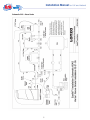
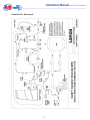
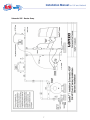
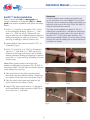
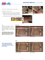
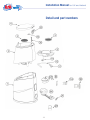
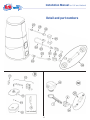
Installation Manual
for UK and Ireland
Model 76826
Issued 05/2014
Arch Chemicals Ltd, a Lonza company.
Wheldon Road, Castleford, West Yorkshire, WF10 2JT
Tel: 01977 714100 Fax: 0870 889 5277
Email: [email protected]
www.lonza.com www.hth.co.uk
® hth and Easiflo are registered trademarks of Arch Chemicals Ltd
www.hth.co.uk
Installation Manual for UK and Ireland
General Principles of Installation
The Easiflo® 1 feeder is an atmospheric system designed for pools ranging from
50 to 300 m3 depending on bather load and operating conditions.
It is possible to install the feeder on a pool and also dose a spa or small pool with a
conventional dosing pump, drawing solution from the discharge tank, but this possibility
again depends on volumes and bather load.
There are different types of installation:
1. As detailed in this manual, above grade or below grade installation which depends on
the location of the pool pump. Both installations use the small feeder venturi to inject
chlorine post filter/heater.
2. Installation using the venturi and booster pump to evacuate the chlorine solution
produced by the feeder into the circulation line of the pool, as shown in Schematic 2BP.
3. Installation using a venturi which employs the motive power of the pools’ own
circulating pump. In this instance consultation with technical services is necessary to
advise on feasibility.
Lonza Technical Services personnel can help with all these matters, tel. 01977 714100 for advice
if needed.
Selecting a location for the Easiflo® 1
Choose a location in the pump room that will allow easy access and service. Always try to
minimize the length of the outlet tubing when locating the Easiflo® 1. The Easiflo® 1 comes
with 6 metres of half inch OD polyethylene tubing.
2
Installation Manual for UK and Ireland
Equipment Required for Feeder Installation
Drill - Cordless Recommended
PVC Primer/Cleaner and PVC Glue
Tube Cutters or Utility Knife
Saw to cut PVC Pipe
/2” BSP Tap and 11/16” Drill Bit
Gas Pliers (Channel Locks)
/2” (M)BSP x 1/4” (F)BSP Reducing Bushing
Vacuum Gauge (Inches of Hg)
1
1
PTFE or Pipe Sealant
Equipment Required for Venturi Installation
1” PVC Pipe and Fittings (elbows, tees etc.)
11/2” BSP Tap and 13/4” Hole Saw (Optional)
Ball or Gate Valve for Pool Return Line
Saddle Clamps (optional)
Parts Included with the Easiflo® 1 Feeder (see pages 11-13 for corresponding part numbers)
1
23 (3) Parker tubing connector: /2” OD tube x
1
/2” (F)BSP (P8FC8) for discharge valve and
flow indicator
1
25 /2” OD Polyethylene Tubing (6 metres)
/2” (F)BSP threaded Sch. 40 PVC coupling for
Venturi
1
27 Arch Venturi (2) 1/2” PVC Nipples
21 (2) 1/2” (F)BSP x (F)BSP PVC ball valve/
W8MC8
1
28 (2) 1 /2” Slip x Slip Sch. 40 PVC Unions,
Venturi fittings
24 0 - 4lts Acrylic Flow Indicator
22 Parker tubing connector: 1/2” Tube x 1/2” (M)
BSP (P8MC4) for ESV inlet
Will the Small Feeder Venturi Work at the
Site?
Install the venturi loop as shown in the appropriate
Installation Schematic for either an above or below
grade filtration system. The primary difference
between the two is the use of ball valves on the
below grade installation to allow the loop to be
isolated from the pool system for service. Once
the loop has been installed using the step by step
instructions in the Installation Manual, adjust the
pressure differential ball valve to achieve a vacuum
reading of 13” Hg.
Backwash or clean the filter and measure the
effluent pressure of the pool system after the
heater at “P1” in the Installation Schematic. If this
pressure is 17psi or less and the minimum flow
rate of the pool is greater than 170 lts /min, the
small feeder venturi will provide adequate suction
to operate the Easiflo® 1. The chart overleaf lists
the suction flow generated by the small feeder
venturi at various pressure differentials.
3
Installation Manual for UK and Ireland
Easiflo® 1 Venturi Installation: Theory
(excluding Booster Pump)
Flow to the venturi is taken from the pressure side
of the pool recirculation pump after the filter and
heater loop (if present). Flow from the venturi is
returned downstream of the venturi inlet. A partially
closed valve in between the venturi inlet and outlet
provides the pressure drop needed to power the
venturi. The three critical parameters in choosing
a venturi are the inlet and outlet pressures and
the suction lift. The Venturi must be capable of
evacuating 4lt /min from the discharge tank when
the filter is dirty. Suction flow will decrease with an
increase in filter pressure as less water will flow
through venturi.
Always minimize the backpressure when installing
a venturi. This includes eliminating/minimizing any
elbows on the outlet side of the venturi. In addition,
if the venturi is located more than 0.9 metres
above the feeder outlet, it will be necessary to
calculate the effect of the suction lift loss on outlet
flow. Follow instructions below to perform the
Suction Lift calculation if required.
Inlet Pressure Outlet Pressure Flow Through Suction Flow
(psi)
(psi)
Venturi (lts /min) ‘F1’ (lts /min)
5.5
5
87
3.78
6
5
106
6.00
6.5
6
91
3.78
7.5
6
106
1.5
7.5
7
98
3.78
8
7
106
4.92
12
10
121
3.78
12.5
10
128
4.92
15.5
12
140
3.78
17.5
15
144
3.78
18
15
148
4.92
21.5
17
155
3.78
22
17
159
4.92
After the evacuation system has been laid out,
measure the height differential (in metres) between
the venturi and discharge valve of the Easiflo®1
feeder. Use this height differential to calculate the
suction lift factor in the formula that follows.
Suction lift factor = (10.37 – height differential in metres) / 10.37
Example: height differential is 2 metres, therefore
Suction lift factor
= (10.37 - 2) / 10.37
= 8.37 / 10.37
= 0.81
Take the suction flow (F1) and multiply it by the suction lift factor to get the actual outlet flow.
The formula is: F1 x suction lift factor = actual outlet flow
The maximum recommended elapsed time to drain
a 2 litre bottle of water (positioned at the same
height of the Easiflo®1 discharge valve) is
30 seconds. This corresponds to an outlet flow-rate
of approximately 4 litres per minute.
After installation, it is important to check the
evacuation cycle of the Easiflo®1 Feeder to
ensure that the drain time of the discharge tank is
adequate.
4
Installation Manual for UK and Ireland
Schematic 2AG - Above Grade
5
Installation Manual for UK and Ireland
Schematic 2BG - Below Grade
6
Installation Manual for UK and Ireland
Schematic 2BP - Booster Pump
7
Installation Manual for UK and Ireland
Easiflo® 1 Venturi Installation
Refer to Schematic 2AG for above grade pool
system installation or Schematic 2BG for a below
grade pool system installation and follow the steps
below.
1 Drill a 13/4” hole (Fig 1) at location “VS1” found
on the schematic drawing. Tap the 13/4” hole
with a 11/2” BSP tap (Fig 2). Options for this
step include the use of saddle clamps instead of
drilling and tapping or splice in a tee with 1” pipe
size (Fig 3) leading to Venturi System loop.
2 Install a Ball or Gate valve at location “PD1” in
Schematic (Fig 4).
Background
The next steps involve creating a bypass loop
on the pool return line for installation of a Venturi.
This loop can be created by drilling and tapping or
splicing into the return line with Tee’s. We refer to
using the drill and tap method.
You may find it preferable to splice in Tee’s to
make these connections. It will also be necessary
to install a ball (or gate) valve in the return line at
location “PD1” in the schematic drawing. This
valve when partially closed, will force water to flow
through the venturi creating the suction needed to
evacuate the feeder.
3 Drill a 13/4” hole (Fig 1) at “VS2” on Schematic.
Tap the 13/4” hole with a 11/2” BSP tap (Fig 2).
Options for this step include the use of saddle
clamps instead of drilling and tapping or splice in
a tee with 11/2” pipe size (Fig 3) leading to Venturi
System loop.
Note: Below grade systems will require the
Fig 1
addition of ball valves at locations “BV1 & BV2” in
schematic #2BG. This will allow the Venturi System
to be isolated for servicing.
Fig 2
4 Take one Union for the Venturi system apart.
Note that they have different halves. Glue these
two halves of the union onto the Venturi (Fig 5).
5 Take the other union apart and install on the
union halves on the Venturi. (Fig 6).
Fig 3
Fig 4
Fig 5
Fig 6
6 Apply PTFE tape to both ends of 1/2” ball valve
and install Parker tubing connector (W8FC8) on
one end of the 1/2” ball valve.
8
Installation Manual for UK and Ireland
7 Install 1/2” ball valve onto venturi (Fig 7).
8 Close the valve (Fig 8).
9 Note the arrow on the venturi indicating the
direction of flow (Fig 9). If there is no arrow
Fig 7
marked on your Venturi, the direction of flow
must go from the shorter end to the longer end.
Fig 8
Fig 9
10
Complete installation of venturi
bypass loop using 11/2” PVC
pipe and fittings. There are four
methods profiled in the following
figures.
Drill & Tap
Note: When performing step 10,
make sure the venturi is installed
with correct direction of flow.
Above Grade
Below Grade
Tees
Refer to glue manufacturers
recommendations regarding
drying times, before re-starting
the pool pump.
Above Grade
Below Grade
9
Installation Manual for UK and Ireland
Connecting the Easiflo® 1 to the Pool
Recirculation System
Adjusting and Testing the Outlet Flow
Rate
1 Place the Easiflo® 1 feeder in the pump room
following the recommendations in the section
‘Selecting a location for the Easiflo 1’.
Install vacuum gauge with 1” MBSP x 1” FBSP
fitting into coupling and install on the Venturi.
2 Drill & Tap /2” BSP hole in effluent pipe @ “T1” in
Installation Schematic.
Start pool system and open all valves on the
venturi loop. Slowly close “PD1” until the vacuum
gauge reads 13” Hg.
1
3 Install nipple and W8MC8 on 1/2” ball valve and
install ball valve in threaded hole.
Close valve to feeder inlet.
Put “Do Not Adjust” tag on “PD1”.
4 Loosen the nut on the tubing connector on
the inlet to the Easiflo® 1 and push the 1/2” OD
polyethylene tubing into the connector and hand
tighten.
5 Flow Indicator Installation
Mount the Flow Indicator (provided with the
Easiflo® 1), where it is easily read.
Remove vacuum gauge and install outlet ball valve
with fitting.
Close the outlet ball valve.
Connect 1/2” tubing to fitting on outlet ball valve.
Re-open feeder water inlet valve.
Check outlet flow with following procedure:
Splice into inlet tubing and connect inlet flow to
bottom port of flow indicator.
Fill a 2 litre bottle with water.
Place near Easiflo®1 Discharge valve.
Connect tubing from feeder inlet to top outlet
port of flow indicator.
6 Run the tubing to the inlet ball valve installed in
step 3 and cut to desired length. Loosen the nut
on the tubing connector on the inlet ball valve
and push the 1/2” OD polyethylene tubing into
the connector and hand tighten.
7 Loosen the nut on the tubing connector on the
discharge valve of the Easiflo® 1 and push the
1
/2” OD polyethylene tubing into the connector
and hand tighten.
Disconnect the tubing from the discharge valve
and place end of tubing at bottom of 2 litre bottle.
Open outlet ball valve and record time it takes to
empty the bottle.
It should take 30 seconds or less to empty the
bottle.This corresponds to an outlet flow rate of
4 lt / min or greater.
Close outlet ball valve and connect tubing to the
discharge valve.
8 Run the tubing to the outlet ball valve on venturi
and cut to desired length. Loosen the nut on
the tubing connector on the outlet ball valve and
push the 1/2” OD polyethylene tubing into the
connector and hand tighten.
The same result can be obtained by emptying
2 litres of water into the feeder base and meauring
the time until the discharge valve closes.
WARRANTY POLICY
The Easiflo® Feeder comes with a 13 month warranty from the date
of purchase from Lonza. For the warranty to be upheld, in the event
of malfunction or damage other than normal wear and tear, all parts
must be returned to us with notification of the feeder’s unique serial
reference number to: Lonza, Arch Chemicals Ltd, Wheldon Road,
Castleford WF10 2JT.
10
Installation Manual for UK and Ireland
Detail and part numbers
11
Installation Manual for UK and Ireland
Detail and part numbers
12
Installation Manual for UK and Ireland
Detail and part numbers
No.
I
2
3
4
5
6
7
8
9
10
II
12
13
14
15
16
17
18
19
20
21
22
23
24
25
26
27
28
29
30
31
32
33
34
35
36
Part
74066
77334
77332
79879
77331
79806
79217
71496
71910
74059
71619
71618
71535
71538
71540
71539
71536
71537
79808
71583
71890
71614
71588
74060
71626
71621/27
71611
71974
77020
79218
77333
77336
71576
352481
79804
Description
EI Base
EI Hopper
EI Grid
EI Lid
EI Dissolving Cup with Nozzles Assembly
Discharge Valve Body
Discharge Valve Arm
Emergency Shut Off Valve Assembly - part 71910 not included
Rubber Gasket for Emergency Shut Off Valve
Parker Fitting W6FE4
Elbow (W6ME6) 3/8” For Feeders 30991 & P3, PI
3/ ” PE Tubing (2 ft)
8
Emergency Shut Off Valve with Arm Only
Emergency Shut Off Float Plate PVC Nut/Discharge Arm Nut
Emergency Shut Off Overflow Float
Emergency Shut Off Float Plate
Emergency Shut Off Mounting Plate
Emergency Shut Off Mounting PVC Screws (1/4 x 20 x 21/4)
Discharge Valve Float
Discharge Valve Locknut
Parker Fitting, W8MC8
Tube Connector (P8MC4) (also for solenoid)
(5008) 112” x 112” Female Connector (P8FC8)
Flow Indicator - EI
6 mts 112” 0.0. PE Tubing
Inlet /Outlet (W8FC8)
1/ ” x close PVC Nipple Parker Tubing Connector
2
White Venturi
Solenoid E1-E3
Grid Hook
Non-Return Valve
Hinge Pin
Hinge
Dishcharge Valve Gasket
Dishcharge Valve Lock Nut Spanner
Discharge Valve Assembly
13
Installation Manual for UK and Ireland
LONZA water treatment products
Emergency Response Procedure for Customers
1. In the event of a Health, Safety or Environmental Emergency involving Lonza water
treatment products. This includes
• Injury to persons requiring medical treatment
• Loss of containment of product to the environment
• Involvement of the Emergency Services (Police, Fire, Medical)
• Involvement of the Environmental agencies
• Major damage to property
FIRST TELEPHONE +44 (0)1235 239670
This will connect you with the NCEC (National Chemical Emergency Centre) who support the
Lonza Emergency Response. (It operates 24 hours a day, 365 days a year).
THEN Phone your local Lonza office (during office hours)
2. NCEC will provide initial assistance and advice (in English).
3. NCEC will also contact Lonza Head Office.
4. When calling the Emergency number, have the following information available (use
your Emergency Response Procedure Checklist):
• Your name
• Your job title
• Your company name and location
• The Telephone (and fax) number that you can be contacted on
• The Product Name
• The Product Code
• The nature of the emergency
• The action you have taken
• Are the emergency services involved?
• Are the environmental agencies involved?
PLEASE ALWAYS CONTACT NCEC IN THE EVENT OF A HEALTH, SAFETY OR
ENVIRONMENTAL EMERGENCY INVOLVING LONZA WATER TREATMENT PRODUCTS
BUT PLEASE ONLY USE THIS NUMBER FOR HEALTH, SAFETY AND ENVIRONMENTAL
EMERGENCIES (as defined above).
14