1
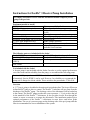
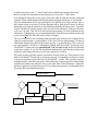
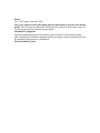
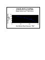
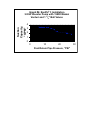
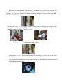
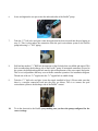
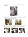
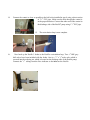
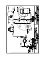
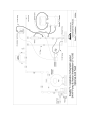
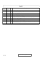
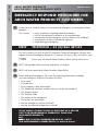
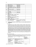
Installation Manual
for the UK and Ireland
Model 71945
Arch Chemicals Ltd
Wheldon Road, Castleford
West Yorkshire, WF10 2JT
7/15/05
REV 11
Product Stewardship
MAKING THE WORLD A BETTER PLACE
Arch is committed to maintaining and improving our leadership in Product
Stewardship. One of the six initiatives outlined under the Chemical
Manufacturers Association (CMA) Responsible Care® Program is to make health,
safety, and environmental protection an integral part of a product’s life cycle from manufacture, marketing, and distribution to use, recycling, and disposal.
Successful implementation is therefore, a shared responsibility. Everyone
involved with the product has responsibilities to address society’s interest in a
healthy environment and in products that can be used safely. We are each
responsible for providing a safe workplace. All who use and handle products
must follow safe and environmentally sound practices.
For more information about our Product Stewardship Program, contact your
Arch Representative.
2
SITE SURVEY
When conducting the site survey and in discussions with the pool operator decide
which type of installation will be carried out.
A single pool installation can be carried out in one of three ways:1. As described in the manual, using the venturi and booster pump to evacuate the
chlorine solution produced by the feeder into the circulation line of the pool.
2. The chlorine solution can be evacuated instead by the use of a conventional
dosing pump.
3. Using a venturi which employs the motive power of the pools’ own circulating
pump. In this instance consultation with Arch technical services is necessary to
advise on feasibility.
For multi pool installations – again the venturi and booster pump can be employed
to evacuate the chlorine solution into the largest of the pools on site. For additional
smaller pools a conventional dosing pump can be used to extract and inject chlorine
solutions from the discharge tank of the feeder. Ensure an adequately sized pump is
employed. Entry to the discharge tank can be gained by drilling an access hole close
to the top of the tank ensuring the hole and subsequent suction line to the pump
does not interfere with the discharge valve arm or float. The dosing pump should
be selected carefully realising that the chlorine solution produced is only around
1.5% of available chlorine. Approximate sizing of pumps for different sizes of pools
are as follows:
Up to:100m3 = 30 l/h
100 – 200m3 = 50l/h
200 – 300m3 = 75l/h
Count 25l/h for each additional 100m3
3
Instructions for Easiflo® 3 Booster Pump Installation
To simplify installation: Please read this installation manual completely before
going to the pool site.
Equipment needed to install:
Drill – Cordless recommended
PVC Pipe Fittings (as required)
PVC Primer/Cleaner
PVC Glue
Saw to cut PVC Pipe
Electricity for the pump (240V)/20 Amp
11/2” PVC pipe (length will vary)
PTFE tape
Tube cutters or Utility Knife
Silicon thread sealant
2 Pipe Wrenches or Gas Pliers (Channel
Locks)
Water tight connectors for pump wiring
Wire for pump (14gauge minimum required)
Pressure gauge
Saddle clamps (optional)
Solenoid valve - we recommend a ………..
In line filter – we recommend a …………..
available from Prominent
The following parts are included with the feeder:
One 1/2” BSP male x male grey ball valve One 1/2” BSP male x female grey ball valve
1
/2” O.D. LDPE tubing
Two 1/2” closed PVC nipples
Two 1/ 2 ” Female Parker tube fittings One Scoop
(P8FC8)
One Venturi
Not included with the feeder:
A booster pump is not included with the feeder. In order to get the optimal performance
out of the feeder and the reliability from the pump, we recommend the following pump:
Sta-rite 1.0 HP pump reference S5P2RE1 available from SCP UK – tel: 01293 546 126
Alternatively Sta-rite 5P2RE1, can be used. However, for reliability we recommend the
pump seal is changed to silicon carbide. These seals have the part number 17304-0100.
Overview
A 11/2” loop is going to be added to the main pool recirculation line. The loop will have an
in-line Easiflo® pump to drive a venturi. The Easiflo® 3 inlet line will get water from the
discharge of the Easiflo® pump. The discharge valve of the chlorinator will be hooked up
to the venturi. The Easiflo® pump provides the correct pressure (~ 35 psi) to drive the jets
in the manifold of the Easiflo® 3 chlorinator. It also provides correct flow through the
venturi to create a vacuum to evacuate the chlorinator. This installation method gives
optimal performance of the Easiflo® 3 chlorinator in most above and below grade
installations. The use of a pressure gauge on the discharge side of the pool pump after the
filter is recommended for correct installation of the system.
4
Easiflo® System Site Assessment
It is critical to determine the effluent pressure of the system prior to installation. This
pressure must be measured immediately after backwashing when it will be at its highest
level. Refer to the appropriate system diagram in the back of this manual to determine
where to measure this pressure (P1).
Take a pressure reading and refer to the graph to determine the suction capacity of the
system assuming that there is no suction lift correction. Record this suction capacity as
F1.
Next, determine where the Easiflo pump and venturi loop will be installed.
Always minimize the backpressure on the venturi. Avoid use of elbows after the venturi if
possible. Never install an elbow within 3 feet of the venturi outlet. Always use elbows on
the inlet to the Easiflo pump or prior to the venturi if possible. After the evacuation
system has been laid out, measure the height differential (in feet) between where the
venturi will be installed and discharge valve of the Easiflo chlorinator. Use this height
differential to calculate the suction lift factor in the formula that follows. The greater the
height differential the more suction you will lose from the venturi. Next calculate the
outlet flow using F1 and the suction lift factor. The minimum outlet flow required is 8.7
litres per minute.
Suction lift factor = (34 – height differential in feet) / 34
Example: height differential is 6 feet, therefore
Suction lift factor = (34-6) / 34
= 28 / 34
= 0.82
Take the suction capacity F1 and multiply it by the suction lift factor to get the actual
outlet flow.
The formula is: F1 x suction lift factor = actual outlet flow
Example #1: Assume that the pressure measured in the pipe is 12psi. Using the P4 graph
1 in this manual the outlet flow (F1) is determined to be 14.4 litres per minute.
F1 x suction lift factor = actual outlet flow
14.4 lt/m x 0.82
=
11.7 lt/m
= actual outlet flow (This flow is acceptable) It is above 8.7 lt/m
which is above the minimum.
Example # 2: Assume that the pressure measured in the pipe is 25psi. Using the P4
graph, the outlet flow (F1) is determined to be 10.2 lt/m
F1 x suction lift factor = actual outlet flow
10.2 lt/m x 0.82
=
8.33 lt/m
= actual outlet flow (This flow is insufficient to drain chlorinator)
It will be necessary to use 11/2” shut-off ball valves in the booster pump/venturi loop.
Refer to Graph #4 to determine suction capacity @ 25 psi with 11/2” ball valves.
Now determine where the power source will come from for both the booster pump and
solenoid. These considerations will help determine the length and gauge of wire needed.
The last consideration for the site assessment is the fill/tap water source and the type of
pH control system to be used. If Carbon Dioxide will be used for pH control, it may be
preferable to provide the inlet flow to the chlorinator from the fill water source. Typically,
Carbon Dioxide pH control systems will raise the Total Alkalinity of the pool water to
well over 100 ppm. This TA level will increase the tendency for scale formation in the
chlorinator. Consequently, it is recommended that the inlet flow be provided from the fill
water source if the TA of the fill water is below 100 ppm.
The use of fill water to the chlorinator inlet will add water to the pool on a daily basis in
relatively small amounts. A typical indoor 375m3 pool will use approximately 75 litres of
chlorinated solution from the Easiflo System per day. A typical outdoor 375m3 pool will
use approximately 225 litres of chlorinated solution from the Easiflo® System per day.
The Easiflo®3 System also puts an additional 3.3m3 of water a day in the pool from the
wash-down system. If you use this installation method make sure that the pool has that
amount of water being removed as to not cause the pool to overflow.
Fill water systems typically operate at pressures between 50-80 psi. This pressure is too
high for the Easiflo® System valves to operate properly. It is therefore necessary to install
a pressure regulator on the inlet flow to the Easiflo® system. This regulator must be
installed directly at the fill water source. This will insure a reduced pressure in the flexible
polyethylene tubing and solenoid valve on the inlet side of the chlorinator. Adjust the
pressure regulator to provide between 30-35 psi inlet water pressure. See diagram below
for proper fill water plumbing hook-up.
Direction of Flow
Fill water
Source
Pressure Regulator
0-60 psi
Inlet Shutoff Valve
Easiflo 3
Inlet
Pump
The 3/4 H.P. pump is wired for 240V.
The power supply to the Easiflo pump must be interlocked to the pool recirculation
pump. This is to prevent running the Easiflo pump dry when the pool pump is shut off.
Use watertight connectors when wiring the pump.
Installation of equipment
Place the equipment, pump and chlorinator, in the poolroom in a convenient location.
Shut off the pool recirculation equipment before proceeding with the installation. Review
the installation diagram prior to installation.
Dealer Installation Notes:
Suction Capacity,
"GPM"
Graph
Pulsar®33Installation
Graph #3:
#3: Easiflo
Installation
3/4 HP
Pump
withwith
1585X
Mazzei
3/4Booster
HP Booster
Pump
1585X
Mazzei
Venturi
1” Ball
Valves
Venturi
and and
1" Ball
Valves
4
3
2
1
0
0
10
20
Pool Return Pipe Pressure, "PSI"
30
® 3 Installation
Graph#4:
#4:Easiflo
Pulsar
Graph
3 Installation
3/4HP
HPBooster
BoosterPump
Pumpwith
with1585X
1585XMazzei
Mazzei
3/4
Venturi and
and 1111/2"
BallValves
Valves
Venturi
/2” Ball
Suction
Capacity,
"GPM"
4
3
2
1
0
0
10
20
Pool Return Pipe Pressure, "PSI"
30
1.
Based on your site assessment, drill and tap a 11/2” BSP hole down stream of the pool filter and
heater. Note: You can use saddle clamps if you wish. This is one of two holes that will be needed in the
installation. The hole should be drilled on the side or bottom of the pipe, if the pipe is horizontal. NOT
ALL PIPES RUN FULL.
2. Cut both of the 12” x 11/2” PVC nipples in half. (4 pieces). Take one of the pieces and apply PTFE
tape to the threads. On top of the PTFE tape add a silicon seal bead around the threads. The silicon
seal helps to make a good seal. Wipe off any excess.
3.
Thread the nipple into the 11/2” tapped hole or saddle clamp.
4.
PTFE tape the 2” X 11/2” reducer bushing and screw and tighten it securely into the inlet of the
Easiflo pump
5.
PTFE tape the threaded end of one of the nipples that was cut in half. Place a bead of silicon seal
around the taped threaded ends.
6.
Screw and tighten the two pieces into the inlet and outlet of the Easiflo® pump.
7.
Take the 11/2” ball valve and glue it onto the nipple that has been screwed into the pool piping in
step #3. This is what makes the connection from the pool recirculation system to the Easiflo
pump inlet using 11/2” PVC piping.
8.
Drill and tap another 11/2” BSP hole downstream of the first hole that was drilled and tapped. This
hole accommodates the discharge side of the Easiflo® pump. If automated controllers are used in
the system, the drilled and tapped hole must be placed downstream of the auto control feed point.
This is to avoid problems that may occur with the controller operation. See installation diagram.
Thread one of the cut 11/2” nipples into the 11/2” tapped hole or saddle clamp.
9.
Take the 11/2” ball valve and glue it onto the nipple installed in Step 8. Please make sure that
there is a straight connection back into the pipe, no elbows. This is to connect the pool
recirculation system to the discharge side of the Easiflo® venturi.
10.
Tie in the electrical to the Easiflo pump making sure you have the pump configured for the
correct voltage.
11.
Using 11/2” PVC piping, connect the inlet side of the Easiflo® pump to the 11/2” ball valve
installed in step 7.
12.
Piping the discharge side of the Easiflo® pump will involve installing a venturi and reducing tee.
See Figure 1 for a reference. Place and glue the 11/2” x 1/2” reducing tee on the 11/2” cut nipple on
the discharge side of the pump. This reducing tee will have a 1/2” male x male ball valve screwed
into it that will provide the inlet water to the chlorinator.
13.
Take the black venturi and PTFE tape all the threaded ends. Take the two unions (makes for easy
removal of venturi, for cleaning, after installation) and screw one on each end and tighten. Take
and thread the 3/4” x 1/2” reducing union to the venturi.
14.
Connect the venturi as close as possible to the ball valve installed in step 8 using a short section
of 11/2” PVC pipe. Make sure the flow through the venturi is
in the proper direction. Connect the other end of the venturi to
the discharge side of the Easiflo® pump using 11/2” PVC pipe.
15.
16.
17.
18.
15. The recirculation loop is now complete.
16.
Now hook up the Easiflo 3 feeder to the Easiflo® recirculation loop. Two 1/2” BSP grey
ball valves have been included with the feeder. One is a 1/2” x 1/2” male valve which is
screwed into the reducing tee, which is located on the discharge side of the Easiflo pump.
Connect the 1/2” tubing from the flow indicator to the inlet on the Easiflo
WARRANTY POLICY
®
Easiflo 3 Commercial Pool Chlorinator
The Easiflo® Chlorine Feeder comes with a 12 month warranty from the date of installation. In order for the warranty to be
validated the Warranty Registration Document W2 must be completed and returned to Arch Water Products, Wheldon
Road, Castleford
WF10 2JT.
Easiflo 3 Feeder Detailed View
2
3
4
1
24
36
Op
era
tor
’s
26
28
25
5
Ma
nu
al
17
7
8
47
56
60
6
9
47
21
30
13
8
28
13
11
26
28
13
10
37
9
20
19
18
38
rev 12-02-02
18
27
37
17
42
11
39
12
38
41
14
15
45
30
(not included)
16
38
32
42
33
29
40
31
44
39
15
23
43
10
22
rev 12-02-02
Installation Kit
flow
to pool
12
6
4
Pu
lsa
Ins
tall
ati
on
r3
Ma
nu
al
cut 1½ “ PVC pipe
(installer provides)
7
3
2
flow er
feed
m
o
fr
3
5
flow r
ede
e
f
o
t
cut 1½ “ PVC pipe
(installer provides)
1½ coupling slip x slip
(installer provides)
6
1
flow ol
po
from
rev 12-02-02
6
4
1½ coupling slip x slip
(installer provides)
cut 1½ “ PVC pipe
(installer provides)
Easiflo 3
Diagram
Number
Part
Number
0
1
71528
71608
1 Easiflo 3 System, PS 5000-Includes Installation Kit
1 Hinge Rod W/Set Screw for E3 Hopper
2
3
71607
71609
1
1
Lid for E3
Briquette Screen Assembly for E3
4
71606
1
Hopper without Lid for E3
5
6
71619
71617
2
3
Elbow (P6ME6) 3/8" For Feeders 30991 & E3
Spray Nozzle for E3
7
8
71616
71620
1
1
Manifold for E3
Deflection Plate Assembly
9
71610
1
Base without assembled parts for E3
10
11
71615
71536
1
1
Discharge Valve Body with Plug, Ball & Gasket
Emergency Shut Off Mounting Plate
12
13
71535
71537
1
4
Emergency Shut Off Valve with Arm Only
Emergency Shut Off Mounting PVC Screws(1/4x20x2 1/4)
14
71539
1
Emergency Shut Off Float Plate
15
16
71538
71540
1
1
Emergency Shut Off Float Plate PVC Nut/Discharge Arm Nut
Emergency Shut Off Overflow Float
17
71496
0
Emergency Shut Off Valve Assembly - Part 71910 Not Included
18
19
71583
71613
2
1
Discharge Valve Locknut
(4026) O-Ring #115 - Used in Plug
20
21
71612
71558
1
Plug for Feeder Body for E3
3/8" O.D. Polyethylene Tubing - 20'
22
71584
1
Discharge Valve Arm with Suction Cup
23
24
71585
71614
1
1
Discharge Valve Float
Tube Connector (P8MC4) for E3
25
26
71621
71626
1
1
1/2" Ball Valve MM (Inlet)
20' 1/2" O.D. PE Tubing(P4 only need 3 inch piece)
27
71627
1
1/2" Ball Valve MF (Outlet)
28
29
71588
71611
3
1
(5008) 1/2" X 1/2" Female Connector (P8FC8)
1/2" X close PVC Nipple
30
31
71910
72863
1
1
Rubber Gasket for Emergency Shut Off Valve
Discharge Valve Enhancement Adaptor
32
71925
2
8 - 32X5/8" PVC Screws
33
34
72865
71373
2 Custom Washer for Discharge Valve Adapter
1 Cleaning pan for Briquette Grid (Easiflo 3)
1/8/2003
Qty
Description
Note: Items 29 through 32 are not shown
Easiflo 3
Diagram
Number
Part
Number
35
36
71598
71622
1 (8001) Scoops (Easiflo Accessory)
1 Operators Manual for E3 System
37
38
72864
71900
0
1
E3 Enchancement Kit
Parker fitting W6ME4
39
71968
2
1/4" Threaded PVC Tee with Nipple
40
41
72862
71572
1
1
Spray Nozzle (Lechler 632.364.5E.BC)
(3045) Reducing Bushing (3/8"x1/4") For Feeder 30025 (PPI)&E3 Enhancement K
42
43
71582
72861
2
1
(4014) Parker Fitting P6MC4
Spray Nozzle (Lechler 632.564.5E.BC)
44
71563
1
(3002) PVC Elbow For Feeders 30025, 30991and P3 Enhancement Kit
45
71574
1
(3103) 3/8" P.E. Tubing E-64-0500 (13.5")
1/8/2003
Qty
Description
Note: Items 29 through 32 are not shown
ISSUE 1 SPRING 2003
ARCH WATER PRODUCTS
RESPONSIBLE CARE GUIDANCE NOTE
AWP RC 2003/1
EMERGENCY RESPONSE PROCEDURE FOR
ARCH WATER PRODUCTS CUSTOMERS
1
In the event of a Health Safety or Environmental Emergency involving Arch Water
products.
This includes
• Injury to persons requiring medical treatment
• Loss of containment of product to the environment
• Involvement of the Emergency Services (Police, Fire, Medical)
• Involvement of the Environmental agencies
• Major damage to property
FIRST
TELEPHONE + 44 (0)1865 407333
This will connect you with the NCEC (National Chemical Emergency Centre) who
support the Arch Emergency Response. (It operates 24 hours a day, 365 days a year).
THEN
Phone your local Arch Water Products Office (during office hours)
2
NCEC will provide initial assistance and advice (in English).
3
NCEC will also contact Arch Water Products Head Office.
4
When calling the Emergency No. have the following information available
(use your Emergency Response Procedure Checklist):
• Your name
• Your job title
• Your company name and location
• The Telephone (and fax) number that you can be contacted on
• The Product Name
• The Product Code
• The nature of the emergency
• The action you have taken
• Are the emergency services involved?
• Are the environmental agencies involved?
PLEASE ALWAYS CONTACT NCEC IN THE EVENT OF A HEALTH,
SAFETY OR ENVIRONMENTAL EMERGENCY INVOLVING
ARCH WATER PRODUCTS
BUT
PLEASE ONLY USE THIS NUMBER FOR HEALTH, SAFETY
AND ENVIRONMENTAL EMERGENCIES (as defined above).