1
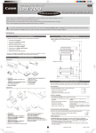
Installation manual
Module series
Version 4.0, June 2012
© KIOTO Photovoltaics GmbH, Solarstraße 1, 9300 Sankt Veit/Glan - Österreich
Please read this installation manual accurately before using the photovoltaic components. The non – observance
could lead to damage to persons and / or goods. Further the guarantee and the product warranty could expire.
The installation of photovoltaic modules requires technical knowledge; therefore this must be done by skilled and
qualified persons!
The general handling of the product, the using and the exact installation are beyond the control area of KIOTO
Photovoltaics GmbH. Therefore KIOTO cannot take responsibility for any damage, loss or cost which is caused
by inappropriate installation, inappropriate handling of the product or wrong use!
General module handling
• Do not open or demount the module
• Do not remove any parts from the module
• Do not remove or damage any product markings
• Do not step on the module
• Do not drop the module
• Avoid any form of external force exposure
• Do not expose the module, especially the module backside to any lacquer, paint, glue, chemicals or other
abrasive liquids
• Do not handle the module at the junction box
• Do not pull on the module cable by heavy handling
• Do not drill any holes in the framework or other components of the module
• Do not interfere with the internal electrical connection of the module. Contact your pv - retailer if problems
occur
• Please consider the maximum system voltage of 1000V
• Never align simulated sunlight on the module or parts of the module
• Observe the mounting and installation instructions of other used components
Product marking, product label
• The product label is placed on the backside of the module and contains all required important electrical and
product specific values. The information on the label relates to EN 50380:2003 and Standard Test Conditions
(1000W/m² - 25°C – AM 1,5)
The product label must not be damaged or removed – otherwise the guarantee and product warranty
will be invalidated!
Please retain this installation manual for future reference!
2
Technical data of the KIOTO Module Series KPV PE QCells - KPV PE NEC KPV ME NEC - KPV ME EC xxxWp (in 5Wp – Steps)
• The modules are configured for the use in DC - systems
• The use of the modules relates to class A: dangerous voltage (IEC 61730: higher than 50V DC, EN 61730:
higher than 120V), dangerous power applications (higher than 240W) which are general accessible,
according to EN IEC 61730 -1 and -2. Protection class II regulations are also fulfilled
• Maximum reverse over current verified according to IEC 61730 -2, MST 26 of the module: 15A
• Nominal current of the diodes SL1515 according to producer designation: 16A
• Under open space conditions the PV – modules could produce higher voltage and/or current, than specified
on the product label. To consider this in the rating dimensioning of other system components, electrical lines,
fuses etc. which are in direct connection to the PV - generator, the values of Isc and Uoc should be multiplied
by the security factor of 1,25 or the sizing should be done by qualified, skilled persons / staff
• Permitted ambient temperature for use and storage: -40°C to + 85°C
• Further technical information is available on the product specific data sheets
Installation instructions for mounting
Consider general health and safety regulations relating to mounting equipment on roofs and/or
buildings. Secure the modules, so that they cannot fall down during mounting and in further operation.
Take care and consider the wind and snow load figures for the affected area. In addition observe the
following:
Electrically:
The following should provide a basis to avoid fire, formation of sparks and deadly electrical shock;
therefore they have to be followed stringently. Remember, in de – energized state, high contact voltage
could occur and / or deadly electric arc can be generated.
• Cover the single modules during the mounting with a photo - resistant material. Description: Modules are
producing electrical energy as soon as the front side is exposed to light. This could happen in connected and
disconnected state. Therefore high voltages which could be perilous are generated
• Never touch cable heads (especially exposed ones) during the mounting, especially when the module is
exposed to light or sunlight
• The electrical tools use for mounting should be approved, isolated and voltage proofed (according to system
voltage)
• Do not bring electrically conducting parts (not isolated tools, jewelry or others) in contact with the PV –
module, the cable heads or the electrical plugs during the mounting
• In case of a roof mounting, additional installations like fuses, dc – disconnectors, earth fault detection etc.
may be necessary. In this case use a qualified, skilled person
• Never use the PV – modules near or in rooms, where flammable liquids or gases are stored or where theses
liquids or gases could escape
• When modules are connected in serial, only modules with the same current should be used. When you are
using a parallel connection, only modules with the same voltage should be used. Never operate the modules
with a higher voltage than the maximum system voltage
• The maximum allowed number of modules used in a serial connection is an outcome of the maximum input
voltage / maximum input current of the used inverters / charge regulators, the used module type and the local
temperature conditions. The system voltage of 1000V must not be exceeded
Installation manual /security advices KIOTO module series
In accordance to safety guideline EN IEC 61730-1 and -2
3
• The maximum reverse over current is 15A. When connecting more than two strings in parallel this value
could be exceeded. Therefore string fuses with a rating of maximum 15A have to be added
Mechanically:
• Mounting works must be done when the environment and tools are dry
• Never use the junction box as handhold
• Consider local factors for example wind force, wind speed and snow load. Calculate these values with a
security factor, before mounting the modules. In special cases, a static calculation must be undertaken.
KIOTO modules are designed and tested to resist a suction force (e.g. wind) of maximum 2400 Pa and a
static pressure force/load (e.g. snow) of maximum 5400 Pa, provided that they are mounted according to the
specified points of application
• Ensure that there is adequate ventilation behind the modules
• To generate optimal output of the PV – generator, consider the perfect alignment and mounting angle of the
PV - modules
• Shadowing of the modules leads to loss of output. Therefore take care that there is no shadowing on the PV
- array
• Never mount KIOTO modules in areas where abnormal (aggressive) conditions could occur
• When the modules are mounted on – roof, ensure that the roofs are fire – resistant or that an appropriate fire
protection layer, designed for this use, is installed. In case of fire, never extinguish with water! Inappropriate
installation could also lead to fire
• The PV – modules must not be installed near flammable gases and liquids (e.g. gasoline stations, gas tanks,
color spraying plants etc.). Never install the module near naked fire or flammable materials
• The PV – module is no LSG (laminated safety glass) - device
• Observe the mounting and installation advices of other used components
Please retain this installation manual for future reference!
4
Fixing points of the KIOTO Module
• Every module must be fixed on four specified points (see Picture 1) with continuous profiles. The frame is
designed and statically tested (snow load: up to 5400pa for all series, wind load: 2400pa for all series; see
Table 1) to be fixed on the longitudinal side. Do not fix on the narrow side
• To resist the named snow and wind loads, the marked distances in picture 1 must be followed when
mounting. To adjust possible tolerances of the substructure, the distance from the top and bottom side of
the module to the mounting profiles should be between 16% and 20% (see Table 2) of the module length. In
case of a longitudinal mounting, the specified mounting points must also be adhered to. If this is not possible
because of the substructure, a crossbar system must be used!
• The fixing of the pv – modules must be done by clamping from the front side. The clamping area at every
clamping point must be a minimum 800 mm². For the fixing of the screws a torque spanner should be used. The rate of acceleration for a screw M8, material: V2A is 20Nm. Always use adequate, corrosion – free
16 - 20% of
module length
mounting material
40 mm
16 - 20% of
module length
Mounting profile
Picture 1
tested mechanical load
Power 36 Series
Power 54 Series
Power 60 Series
5400pa / 2400pa
5400pa / 2400pa
5400pa / 2400pa
(snow load/wind load)
Table 1
Power 36 Series
Power 54 Series
Power 60 Series
min. distance
240mm
240mm
266mm
max. distance
300mm
300mm
333mm
module length
1507mm
1507mm
1666mm
Table 2
Installation manual /security advices KIOTO module series
In accordance to safety guideline EN IEC 61730-1 and -2
5
Electrical connection of the PV – generator
• At high direct current voltages, as can occur in serial connections, the risk of short circuits and electric arcs is
higher. To avoid this, always use an adequate cross section for cables and connectors, which are approved
for the maximum specified value of open circuit voltage. KIOTO modules are equipped with Tyco Solarlok
junction box and cables that are designed specifically for the product. The solar cable is an isolated, whether
and UV – resistant product with a dimension of 4mm² (Type LTCC according to the Tyco specifications)
• At strong currents, as can occur in parallel connections, the risk of warming of the connections is higher. To
avoid this risk use an adequate sizing of the cross section
• The solar cables must be approved for the possible maximum short circuit current
Detailed information about the connection technique, solar cable and
connectors / plugs:
• Only use cables and connectors/plugs which are approved and tested for photovoltaic applications
• The choice of cables for the use in the pv – generator must be based on sizing by a skilled person.
Cables with a cross section from 4mm² to 6mm² are recommended. The optimum cross section should be
determined by the maximum short circuit voltage and the complete length of the wiring (line voltage drop)
• Only use high quality cables to assure a failure – free operating. Ensure good isolation and whether / UV
- durability of the cables
• The rated voltage of the solar cable must be 1000V minimum
• If possible, use flexible cables to ensure consistency against movements, wind etc. This will make the laying
of the cables easier (please find detailed information in the next clause)
• Only use tools which are approved for cutting, isolating etc. of the cables or employ qualified persons / staff
• Further information about the connectors are available at the Tyco Electronics documentations
○○ SOLARLOK Application Specifications 114-18488-1
○○ SOLARLOK Instruction Sheet 411-18305-1
○○ SOLARLOK Interconnection System Installation Manual 1654276-1
Please retain this installation manual for future reference!
6
Connectors / plugs:
• Only use connectors / plugs which are approved and tested for photovoltaic applications
• Connect the plugs only in dry state and ensure a proper connection
• Safety advice: Never disconnect the plugs under load (when the generator is in operation). Non – compliance
with this could have serious consequences! This safety device is also printed on the delivered cables and the
label of the PV - modules
• The connector system is fully latched only when the latches have clicked onto the mating connector or
junction box.
Picture 2
Picture 3
Assembly steps connector:
1. Using the appropriate wire stripping tool, strip the wire 9 mm ± 1 mm without damaging the strands.
Picture 4
2. Insert the stripped wire into the terminal wire crimp barrel until it stops. While holding the wire in place,
squeeze the crimp tool handles together until the ratchet releases.
Picture 5
Installation manual /security advices KIOTO module series
In accordance to safety guideline EN IEC 61730-1 and -2
7
3. Press the seal and cable pinch ring assembly into the connector housing until it stops. If you use the preassembled connector kit, please go to 5!
Picture 6
4. Screw back shell nut onto connector housing.
Picture 7
5. Push contact with cable into the connector housing until you hear the contact give an audible click and you
feel the contact reach the end position. To verify contact engagement, give a slight gentle pull back on the
cable, to be sure that the contact is locked.
Picture 8
6. Tighten the cable screw lock. The initial assembly tightening torque is 1.3 + 0.2 Nm. For this, a slotted socket
wrench with wrench size 13 mm, is recommended.
Picture 9
• Safety Note: Never disconnect the connectors under load, that means while the generator is operating. Noncompliance can be perilous. This safety advice is also printed on the module cables and at the label of the
PV-modules.
Please retain this installation manual for future reference!
8
Laying of the solar cables:
• Keep the length of cable connections as short as possible, to optimize the energy yield and minimize sources
of errors. Consider this point while planning and sizing the generator
• Fix loose solar cables after mounting to avoid damaging. Use only adequate fixing material (conduits in the
mounting profiles or UV – resistant plastic tubes)
• Take care while handling the cables to avoid damaging, especially at low temperatures
• The cables should not be bent or folded in an extreme way. Where possible use flexible cables. Please follow
supplier instructions
• Use conduits for laying and fixing of the cables
• To avoid voltages from indirect lightning strikes, lay the feed line and return line very close to each other
• Always consider the polarity
• The cables must not lie between the mounting profiles and module backside to avoid damaging the module,
especially under heavy mechanical load.
Electrical connection:
• Modules must be covered with a photo – resistant material during the whole mounting process
• Avoid damaging the cables
• Execute the system grounding according to national and international standards
• Sizing of inverters should be done before mounting by qualified persons to ensure an optimized energy yield
• For security reasons and to minimize maintenance works, a DC – disconnector should be installed between
the generator and the inverter. This could also be obligatory by law.
Installation manual /security advices KIOTO module series
In accordance to safety guideline EN IEC 61730-1 and -2
9
Connection of the PV – module to a grounding system (Power 54 series)
• The grounding of the module could be realized in two of four corners of the module. At the inside of the
module framing, in the area of the edge connector, you will find an obvious grounding lug with a through hole
for M6 (minimum M4) screws.
• The chosen grounding lug must be bent out of the module frame carefully (about 90° - see picture 2).
Grounding lugs which are bended out by mistake must be left in this end position
• The adequately sized grounding cable must be connected with a stainless steel screw M6 x 20mm with
two fan shaped washers (on the outside and inside of the grounding lug) and a self locking screw nut. The
assembly from the outside to the inside should be: screw head – fan shaped washer – GROUNDING LUG –
fan shaped washer – eyelet – self locking screw nut
• For the professional grounding of the complete pv – system the installer is responsible. If a grounding system
is already in use at the affected building, the pv – generator has to be integrated in this protection system
against direct lightning strikes. National standards have to be considered and executed
Picture 10
Please retain this installation manual for future reference!
10
Connection of the PV – module to a grounding system (Power 60 series)
• The grounding of the module could be realized all four corners of the module. At the inside of the module
framing, in the area of the edge connector, you will find an obvious drill hole for ISO 7981 screws.
• The adequately sized grounding cable must be connected with a stainless stell (A2) ISO 7981 screw (3,9 x
6,5mm) with a form C rounded head with two fan shaped washers (on the outside and inside of the eyelet).
The assembly from the outside to the inside should be: screw head – fan shaped washer – eyelet – fan
shaped washer – frame
• For the professional grounding of the complete pv – system the installer is responsible. If a grounding system
is already in use at the affected building, the pv – generator has to be integrated in this protection system
against direct lightning strikes. National standards have to be considered and executed
Erdungskabel mit Kabelschuh
2x Fächerscheibe
Blechschraube nach ISO 7981 A4
Form C
Picture 11
Installation manual /security advices KIOTO module series
In accordance to safety guideline EN IEC 61730-1 and -2
11
Initiation of the PV generator
Before initiation of the generator, please check all components (observe the installation instructions of other
components), the electrical connection and all plugs, that they are connected correctly and ensure that the
connection is tight.
Solar generators with a direct current voltage from more than 50V must be installed / initiated by
qualified persons!
• The open circuit voltage of every serial connection should be checked after initiation. Follow the rule: Result
of the measurement = sum of the open circuit voltages of the single modules
• Consider the actual time, sun irradiation, shadowing and other factors while measuring the open circuit
voltage, otherwise the result of the sum and the single results could deviate considerably
Maintenance
• Clean the modules as necessary (according to the degree of pollution) with plenty of water, a smooth cloth
and without any detergent. If other additives or devices like aggressive chemicals, scrubbing agents, sharp
blades or steel – wool are used the guarantee and product warranty will be invalid! Never wipe off or scrape
off pollution in a dry state of the module surface
• Check the module wiring and the single module plugs to ensure they are clean, corrosion – free,
mechanically ok and tight in regular intervals.
Attention: Never disconnect the plugs under load!
• Free the modules, if necessary, from high snow loads
• Also check the substructure in regular intervals for their tightness
• Never try to open or repair parts of the module or of the junction box on your own • All other trouble shootings, repairing and maintenance works must be done by qualified, skilled staff / persons
For further information relating to warranties etc. please read through the GENERAL TERMS AND
CONDITIONS of KIOTO Photovoltaics
© KIOTO Photovoltaics GmbH, Solarstraße 1, 9300 Sankt Veit/Glan - Österreich
Art.Nr.: 6903944