1
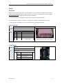
Ultra-Lite and Lite Qseven Carrier Boards User Manual Connect Tech Inc. 42 Arrow Road Guelph, Ontario N1K 1S6 Tel: Toll: Fax: Email: Web: 519-836-1291 800-426-8979 (North America only) 519-836-4878 [email protected] [email protected] www.connecttech.com CTIM-00068 Revision: 0.03, Nov 1, 2013 Connect Tech Ultra Lite and Lite Qseven Carrier Boards - User Manual Table of Contents Customer Support Overview .......................................................................................................................... 5 Contact Information........................................................................................................................................ 5 Limited Lifetime Warranty ............................................................................................................................. 6 Copyright Notice ............................................................................................................................................ 6 Trademark Acknowledgment ......................................................................................................................... 6 Revision History ............................................................................................................................................. 6 Introduction .................................................................................................................................................... 8 What is Qseven? ....................................................................................................................................................... 8 ESD Warning ............................................................................................................................................................ 8 Product Features........................................................................................................................................................ 9 System Block Diagram ........................................................................................................................................... 10 Hardware Description ....................................................................................................................................11 Ultra Lite Qseven Carrier Board Connector Locations ........................................................................................... 11 QCG005 ...........................................................................................................................................................11 QCG0011 .........................................................................................................................................................11 QCG0015 .........................................................................................................................................................12 Lite Connector and Jumper Summary ..............................................................................................................12 Lite Qseven Carrier Board Connector Locations .................................................................................................... 13 Lite – Bottom ...................................................................................................................................................13 Lite Connector and Jumper Summary ..............................................................................................................14 Ultra-Lite Carrier Connector Descriptions ....................................................................................................15 Qseven Module Interface ........................................................................................................................................ 15 Description ....................................................................................................................................................15 Connector......................................................................................................................................................15 Video....................................................................................................................................................................... 15 HDMI ...............................................................................................................................................................15 LVDS ...............................................................................................................................................................16 Description ....................................................................................................................................................16 LVDS Video Header .....................................................................................................................................16 LVDS Backlight ...............................................................................................................................................17 LVDS Backlight connector ...........................................................................................................................17 LVDS Backlight Power Jumper ....................................................................................................................17 Power for LVDS Panel Circuits ....................................................................................................................17 LVDS backlight enable polarity....................................................................................................................18 USB Operations ...................................................................................................................................................... 19 User USB Ports ................................................................................................................................................19 Connector......................................................................................................................................................19 USB Ports on MiniPCIe connectors .................................................................................................................19 RS232 Serial ........................................................................................................................................................... 20 Description ....................................................................................................................................................20 Connector & Jumper .....................................................................................................................................20 SATA ...................................................................................................................................................................... 21 Description ....................................................................................................................................................21 Connector & LEDs .......................................................................................................................................21 miniPCIe ................................................................................................................................................................. 22 miniPCIe SIM Card .........................................................................................................................................22 miniPCIe WiFi Status LEDs ............................................................................................................................23 2 Revision 0.03 Connect Tech Ultra Lite and Lite Qseven Carrier Boards - User Manual miniPCIe WiFi Jumpers ...................................................................................................................................23 Off board status LEDs............................................................................................................................................. 23 Ultra Lite Version ............................................................................................................................................23 Note: Odd pins are connected to 3.3V or 5V with a 470ohm resistorMicro SD Card............................................. 23 Description ....................................................................................................................................................24 Power ...................................................................................................................................................................... 25 Description ....................................................................................................................................................25 Power Connectors .........................................................................................................................................25 +5VSB Jumper (QCG005 Only, QCG011/QCG015 permanently connect +5V SB to +5V) .......................26 Power Good Jumper ......................................................................................................................................26 Module Current Requirements ......................................................................................................................26 Current Consumption information ................................................................................................................26 J3 Miscellaneous Functions .................................................................................................................................... 27 UltraLite Carrier Hardware Installation .................................................................................................................. 28 Lite Carrier Connector Descriptions ..............................................................................................................29 Qseven Module Interface ........................................................................................................................................ 29 Description ....................................................................................................................................................29 Connector......................................................................................................................................................29 Video....................................................................................................................................................................... 29 HDMI ...............................................................................................................................................................29 LVDS ...............................................................................................................................................................30 Description ....................................................................................................................................................30 LVDS Video Header .....................................................................................................................................30 LVDS Backlight ...............................................................................................................................................31 LVDS Backlight connector ...........................................................................................................................31 LVDS Backlight Power Jumper ....................................................................................................................31 Power for LVDS Panel Circuits ....................................................................................................................31 LVDS backlight enable polarity....................................................................................................................32 USB Operations ...................................................................................................................................................... 32 User USB Ports ................................................................................................................................................32 Connector......................................................................................................................................................32 USB Client/Host Port Mode.............................................................................................................................33 USB Client Host Operation...........................................................................................................................33 USB Ports on MiniPCIe connectors .................................................................................................................33 RS232 Serial ........................................................................................................................................................... 34 Description ....................................................................................................................................................34 Connector & Jumper .....................................................................................................................................34 SATA ...................................................................................................................................................................... 35 Description ....................................................................................................................................................35 Connector & LEDs .......................................................................................................................................35 miniPCIe ................................................................................................................................................................. 36 miniPCIe SIM Card .........................................................................................................................................36 miniPCIe WiFi Status LEDs ............................................................................................................................37 Off board status LEDs............................................................................................................................................. 37 Battery and I2C Interface ........................................................................................................................................ 38 Partial Schematic..............................................................................................................................................38 Debug JTAG and RS232 on Lite Version ............................................................................................................... 39 Circuit Schematic .............................................................................................................................................39 Micro SD Card ........................................................................................................................................................ 40 Description ....................................................................................................................................................40 Power ...................................................................................................................................................................... 41 Description ....................................................................................................................................................41 Power Connectors .........................................................................................................................................41 Revision 0.03 3 Connect Tech Ultra Lite and Lite Qseven Carrier Boards - User Manual +5VSB Jumper ..............................................................................................................................................41 Power Good Jumper ......................................................................................................................................42 Module Current Requirements ......................................................................................................................42 Current Consumption information ................................................................................................................42 J3 Miscellaneous Functions .................................................................................................................................... 42 Lite Carrier Hardware Installation .......................................................................................................................... 43 Software Installation & Configuration ..........................................................................................................44 Operating System Notes .......................................................................................................................................... 44 Linux ................................................................................................................................................................44 US15W Specific ...........................................................................................................................................44 Windows ..........................................................................................................................................................44 US15W Specific ...........................................................................................................................................44 Cables & Interconnect ...................................................................................................................................45 Dimensions Ultra Lite Qseven Carrier Boards ..............................................................................................46 Dimensions Lite Qseven Carrier Board .........................................................................................................47 Part Numbers .................................................................................................................................................48 4 Revision 0.03 Connect Tech Ultra Lite and Lite Qseven Carrier Boards - User Manual Customer Support Overview If you experience difficulties after reading the manual and/or using the product, contact the Connect Tech reseller from which you purchased the product. In most cases the reseller can help you with product installation and difficulties. In the event that the reseller is unable to resolve your problem, our highly qualified support staff can assist you. Our support section is available 24 hours a day, 7 days a week on our website at: www.connecttech.com/sub/support/support.asp. See the contact information section below for more information on how to contact us directly. Our technical support is always free. Contact Information We offer three ways for you to contact us: Mail/Courier You may contact us by letter at: Connect Tech Inc. Technical Support 42 Arrow Road Guelph, Ontario Canada N1K 1S6 Email/Internet You may contact us through the Internet. Our email and URL addresses on the Internet are: [email protected] [email protected] www.connecttech.com Note: Please go to the Download Zone or the Knowledge Database in the Support Center on the Connect Tech website for product manuals, installation guides, device driver software and technical tips. Submit your technical support questions to our customer support engineers via the Support Center on the Connect Tech website. Telephone/Facsimile Technical Support representatives are ready to answer your call Monday through Friday, from 8:30 a.m. to 5:00 p.m. Eastern Standard Time. Our numbers for calls are: Toll Free: 800-426-8979 (North America only) Telephone: 519-836-1291 (Live assistance available 8:30 a.m. to 5:00 p.m. EST, Monday to Friday) Facsimile: 519-836-4878 (on-line 24 hours) Revision 0.03 5 Connect Tech Ultra Lite and Lite Qseven Carrier Boards - User Manual Limited Lifetime Warranty Connect Tech Inc. provides a Lifetime Warranty for all Connect Tech Inc. products. Should this product, in Connect Tech Inc.'s opinion, fail to be in good working order during the warranty period, Connect Tech Inc. will, at its option, repair or replace this product at no charge, provided that the product has not been subjected to abuse, misuse, accident, disaster or non-Connect Tech Inc. authorized modification or repair. You may obtain warranty service by delivering this product to an authorized Connect Tech Inc. business partner or to Connect Tech Inc. along with proof of purchase. Product returned to Connect Tech Inc. must be pre-authorized by Connect Tech Inc. with an RMA (Return Material Authorization) number marked on the outside of the package and sent prepaid, insured and packaged for safe shipment. Connect Tech Inc. will return this product by prepaid ground shipment service. The Connect Tech Inc. Lifetime Warranty is defined as the serviceable life of the product. This is defined as the period during which all components are available. Should the product prove to be irreparable, Connect Tech Inc. reserves the right to substitute an equivalent product if available or to retract Lifetime Warranty if no replacement is available. The above warranty is the only warranty authorized by Connect Tech Inc. Under no circumstances will Connect Tech Inc. be liable in any way for any damages, including any lost profits, lost savings or other incidental or consequential damages arising out of the use of, or inability to use, such product. Copyright Notice The information contained in this document is subject to change without notice. Connect Tech Inc. shall not be liable for errors contained herein or for incidental consequential damages in connection with the furnishing, performance, or use of this material. This document contains proprietary information that is protected by copyright. All rights are reserved. No part of this document may be photocopied, reproduced, or translated to another language without the prior written consent of Connect Tech, Inc. Copyright 1997 - 2013 by Connect Tech, Inc. Trademark Acknowledgment Connect Tech, Inc. acknowledges all trademarks, registered trademarks and/or copyrights referred to in this document as the property of their respective owners. Not listing all possible trademarks or copyright acknowledgments does not constitute a lack of acknowledgment to the rightful owners of the trademarks and copyrights mentioned in this document. Revision History 6 Rev 0.00 0.01 Date June 3, 2011 Oct 3, 2012 0.02 0.03 April 3, 2013 Oct 24, 2013 Change Original Document Updated features for QCG006 including GBE, JTAG, USB Client/Host, and RS232. Added information on QCG011/12 Split Ultra Lite and Lite Carrier information, added QCG015 Revision 0.03 Connect Tech Ultra Lite and Lite Qseven Carrier Boards - User Manual Revision 0.03 7 Connect Tech Ultra Lite and Lite Qseven Carrier Boards - User Manual Introduction Connect Tech’s Ultra Lite and Lite Qseven Carrier Boards are small low cost, feature rich carriers that integrate with any industry standard Qseven module. These bus-independent carrier boards offer easy connection to SATA, USB, Ethernet, LVDS and VGA video, and RS-232 with MiniPCIe and SIM-card expansion capability. Mini-PCIe peripherals such as WiFi, GPS, Bluetooth, or storage are optional. Ultra Lite and Lite Qseven Carrier Boards offer several processor options including Intel® Atom™, Freescale i.MX51, TI OMAP, and NVIDIA Tegra, which are easily upgradable to accommodate future generations. Connect Tech’s Qseven carrier boards are ideal for compact computing applications in mobile entertainment, kiosks, digital signage, soldier wearable systems and gaming. What is Qseven? Qseven is an off-the-shelf, multi-vendor, computer-on-module that integrates the core components of a common PC. The Qseven standard allows upgrading to the latest processor and memory technology with ease, while maintaining the I/O interfaces. To learn more about Connect Tech’s Qseven carrier, visit http://www.connecttech.com/Qseven. ESD Warning Electronic components and circuits are sensitive to ElectroStatic Discharge (ESD). When handling any circuit board assemblies including Connect Tech Qseven carrier assemblies, it is recommended that ESD safety precautions be observed. ESD safe best practices include, but are not limited to: 8 Leaving circuit boards in their antistatic packaging until they are ready to be installed. Using a grounded wrist strap when handling circuit boards, at a minimum you should touch a grounded metal object to dissipate any static charge that may be present on you. Only handling circuit boards in ESD safe areas, which may include ESD floor and table mats, wrist strap stations and ESD safe lab coats. Avoiding handling circuit boards in carpeted areas. Try to handle the board by the edges, avoiding contact with components. Revision 0.03 Connect Tech Ultra Lite and Lite Qseven Carrier Boards - User Manual Product Features Ultra Lite Qseven Carrier Feature Part Number Lite Qseven Carrier QCG005 QCG011 QCG015 QCG006 Pico ITX, 72x100mm Pico ITX, 72x100mm Pico ITX, 72x100mm 128x100mm Mini-PCIe Expansion 1 1 - 2 mSATA Expansion - - 1 - SIM Card Connector 1 1 - 2 USB on MiniPCIe - Yes - Yes LVDS Video & Backlight controls Yes Yes Yes Yes HDMI Video/Audio - - Yes Yes JTAG/RS232 Debug - - - Yes Battery I2C Interface - - - Yes Giga Bit Ethernet - Yes Yes Yes USB Client Port - Yes Yes Yes USB Ports 4 4 4 4 SATA Ports 1 1 1 RS232 Serial Port - - Yes SD Card - - MicroSD MicroSD RTC 3.3V Battery Yes Yes Yes Yes Power Connectors Molex HDD Screw Terminal Yes Optional Yes Optional Optional Yes Yes Optional Optional cable kit Optional cable kit Optional cable kit Optional cable kit Size Accessories [1] [1] [1] 2 Y [1] The RS232 serial port and the USB Client/Host port are shared with the USB Ports. Revision 0.03 9 Connect Tech Ultra Lite and Lite Qseven Carrier Boards - User Manual System Block Diagram Atom based Qseven modules implement the core processing features including: processor, memory, and system physical interfaces via the south bridge. Many of the Qseven modules are based on the mobile Intel® Atom™ architecture (Z series processor + SCH US15W chipset), shown in the block diagram below. This document will generally refer to the features of the US15W. Note: Some features shown above may not be present on all part numbers. 10 Revision 0.03 Connect Tech Ultra Lite and Lite Qseven Carrier Boards - User Manual Hardware Description Ultra Lite Qseven Carrier Board Connector Locations QCG005 J2 - Power up Config LEDS P15 - SIM Card WWAN D 7 WLAN D8 WPAN D 9 SATA D 1 J3 - Misc Operations J1 - Q7 Standby Power P13 - USB miniPCIe P9 - DC POWER P3A USB Ports 1&2 P3B USB Ports 3&4 P2 SATA P3C Not installed J10 LVDS Power Selection J6 LVDS Backlight Voltage Selection P7 - LVDS Backlight P4 - LVDS Display P12 - miniPCIe QCG0011 J2 - Power up Config LEDS P15 - SIM Card WWAN D 7 WLAN D8 WPAN D 9 SATA D 1 J3 - Misc Operations P6 - Gigabit Ethernet P9 - DC POWER P8 - USB Client P3A USB Ports 1&2 P2 SATA P3B USB Ports 3&4 J10 LVDS Power Selection J6 LVDS Backlight Voltage Selection Revision 0.03 P7 - LVDS Backlight P4 - LVDS Display P12 - miniPCIe 11 Connect Tech Ultra Lite and Lite Qseven Carrier Boards - User Manual LEDS WWAN D7 WLAN D8 WPAN D9 SATA D1 (bottom) P13 - RS-232 P11 - HDMI J2 - Power up Config J3 - Misc Operations P14 - MicroSD QCG0015 P6 - Gigabit Ethernet P9 - DC POWER P8 - USB Client P3A USB Ports 1&2 P2 SATA (SATA1) P3B USB Ports 3&4 J10 LVDS Power Selection J6 LVDS Backlight Voltage Selection P4 - LVDS Display P7 - LVDS Backlight P12 - mSATA (SATA0) Lite Connector and Jumper Summary Connector Summary QCG005 QCG011 P1 P1 P2 12 Jumper Summary QCG015 Connection Jumper Function P2 mSATA (P12) Q7 J6 LVDS Backlight voltage selection SATA 0 J10 - - P2 LVDS Power selection SATA 1 J2 Power-UP Configuration P3A P3A P3A USB Ports 1 and 2 J3 Misc. Operations P3B P4 P3B P3B USB Ports 3 and 4 P4 P4 LVDS Display P7 P7 P7 LVDS Backlight Power P9 P9 - Molex 4 position DC Power - - P5 Screw Term DC Power P12 P12 - miniPCIe P15 P15 - SIMCard - - P11 HDMI - P6 P6 GB Ethernet - P8 P8 USB Client Port - - P13 RS-232 - - P14 Micro SD Card Revision 0.03 Connect Tech Ultra Lite and Lite Qseven Carrier Boards - User Manual Lite Qseven Carrier Board Connector Locations L10 0 ACT L10 00 WWAN WL AN WPAN SATA PWR WWAN WL AN WPAN Status LEDS P14 HDMI Type A SIM Card 2 P17 RS232 Serial Client Mode USB Port MiniPCIe 2 P2B SATA2 J8 J10 P7 +12V P7 - DC GND POWER GND +5V J4 SIM Card 1 J1 P19 Micro SD Card P9 Debug Port P3A USB Ports 1&2 MiniPCIe 1 P2A SATA1 P3B USB Ports 3&4 J3 Ethernet J5 P7 - LVDS Backlight P4 - LVDS Display Lite – Bottom QSeven connector Revision 0.03 13 Connect Tech Ultra Lite and Lite Qseven Carrier Boards - User Manual Lite Connector and Jumper Summary Connector Summary Location 14 Jumper Summary Connection Jumper Function Qseven +5V Standby power P1 Q7 J1 P2A SATA 1 J3 LVDS Power selection P2B SATA 2 J7 Miscellaneous operations P3A USB Ports 1 and 2 J5 LVDS Backlight voltage selection P3B USB Ports 3 and 4 J4 Power up configuration P4 LVDS Display J8 USB Client/Host and RS232 Mux P5 LVDS Backlight Power P6 Molex 4 position DC Power P7 Optional Screw Term DC Power P8A miniPCIe 1 P8B miniPCIe 2 P9 JTAG/RS232 Debug P10A SIMCard 1 P10B SIMCard 2 P11A LED header for miniPCIe 1 + SATA P11B LED header for miniPCIe 2 + Power P14 HDMI P15 GB Ethernet P16 USB Client Port P17 RS232 P18 Micro SD Card P19 I2C Battery Interface Revision 0.03 Connect Tech Ultra Lite and Lite Qseven Carrier Boards - User Manual Ultra-Lite Carrier Connector Descriptions Qseven Module Interface Description The processor and chipset are implemented on the Qseven CPU module, which connects to the Qseven carrier via a MXM connector. Many of the existing Qseven modules use the Intel® Atom™ mobile architecture, Z series processor SCH US15W chipset. The Qseven carrier implements a subset of the Qseven features, as described in the introduction. For a list of Qseven module vendors, visit http://www.qseven-standard.org/ Connector Function Qseven interface Location P1 Type MXM Foxconn AS0B326-S78N-7F (or equivalent) Pinout Refer to Qseven specification Video The availability of the graphics interfaces depends on the Qseven module selected. US15W: The US15W chipset provides GMA 500 graphics sub-system and provides two display interfaces: SDVO (serial digital video output) and LVDS (low voltage differential signalling). The resolution generated by the GMA 500 is limited 1280x1024. ARM:Many of the ARM based Qseven modules support LVDS and HDMI interfaces. The configuration of either interface as the primary or secondary display depends on the Qseven module’s BIOS capabilities and settings. Refer to the Qseven module’s documentation for more details. HDMI A micro HDMI connector is provided on the QCG015 carrier. Function HDMI Location P14 Type Micro HDMI Type D Revision 0.03 15 Connect Tech Ultra Lite and Lite Qseven Carrier Boards - User Manual LVDS LVDS Video is provided on all of the Ultra Lite Qseven Carrier Boards. Description The Qseven carrier provides dual 18 or 24 bit LVDS display channels via P4, which are connected directly from the Qseven module. LVDS panel supply power is selected with jumper J104 and backlight power is selected with jumper J6. Both are current limited to 500 mA. US15W: The US15W provides only a single 18 or 24 bit display channel. Each LVDS data pair carries two bits, each channel has four data pairs. LVDS Video Header Function LVDS Graphics Location P4 Type Hirose DF14-30P-1.25H connector Pinout 16 Pin Signal Description 1 VCC_PNL Panel Power 2 VCC_PNL Panel Power 3 GND Digital ground 4 GND Digital ground 5 LVDS_A3_N Channel A Data 6 LVDS_A3_P Channel A Data 7 LVDS_CLK_N Channel A Clock 8 LVDS_ACLK_P Channel A Clock 9 GND Digital ground 10 LVDS_A2_N Channel A Data 11 LVDS_A2_P Channel A Data 12 LVDS_A1_N Channel A Data 13 LVDS_A1_P Channel A Data 14 LVDS_A0_N Channel A Data 15 LVDS_A0_P Channel A Data 16 GND Digital ground 17 LVDS_B3_N Channel B Data 18 LVDS_B3_P Channel B Data 19 LVDS_BCLK_N Channel B Clock 20 LVDS_BCLK_P Channel B Clock 21 GND Digital ground 22 LVDS_B2_N Channel B Data 23 LVDS_B2_P Channel B Data 24 LVDS_B1_N Channel B Data 25 LVDS_B1_P Channel B Data 26 LVDS_B0_N Channel B Data 27 LVDS_B0_P Channel B Data 28 GND Digital ground 29 LVDS_DID_CLK Display ID Clock (3.3V) 30 LVDS_DID_DATA Display ID Data (3.3V) Revision 0.03 Connect Tech Ultra Lite and Lite Qseven Carrier Boards - User Manual LVDS Backlight LVDS Backlight connector Function LVDS backlight power Location P7 Type Hirose DF13-8P-1.25H connector Pinout Pin Signal Description 1 +12V +12 V DC, max. 1A 2 +12V +12 V DC, max. 1A 3 +5V +5 V DC, max. 1A 4 +5V +5 V DC, max. 1A 5 LVDS_BLEN Backlight enable, level selected with J4 6 VCC_BKL Back light power, selected with J6 7 GND Digital ground 8 GND Digital ground LVDS Backlight Power Jumper Function LVDS backlight power select Selects either +12V or +5V. Refer to the display panel’s documentation for proper configuration. Location J6 Type 1x3 0.100” jumper block Pinout Default Position Description 1-2 +5V 2-3 +12V off floating +12V Power for LVDS Panel Circuits Function LVDS panel power select Selects either +3.3V or +5V. Refer to the display documentation for proper configuration. Location J10 Type 1x3 0.100” jumper block Pinout Default Position Description 1-2 +5V 2-3 +3.3V off floating +3.3V Revision 0.03 17 Connect Tech Ultra Lite and Lite Qseven Carrier Boards - User Manual LVDS backlight enable polarity Function LVDS backlight enable polarity Selects either positive or negative. Refer to the inverter power supply documentation for proper configuration. Location J5 Type 1x2 2mm jumper block Pinout Default 18 Position 1-2 Description Off Positive polarity On Negative polarity Positive polarity Revision 0.03 Connect Tech Ultra Lite and Lite Qseven Carrier Boards - User Manual USB Operations User USB Ports The UltraLite carriers implement 4 of the available USB 2.0 connections via two connectors. Over current protection and power supply filtering is provided. Assume USB Port numbering starts at USB Port 0. Connector Function USB 2.0 x2 Locations P3A, P3B Type Hirose DF13-8P Pinout Pin Signal Description 1 VCC_USB_0 Port 0 Filtered +5V 2 USB_0_N Port 0 Data 3 USB_0_P Port 0 Data 4 USB_GND_0 Port 0 Filtered Digital Ground 5 USB_GND_1 Port 1 Filtered Digital Ground 6 USB_1_N Port 1 Data 7 USB_1_N Port 1 Data 8 VCC_USB_1 Port 1 Filtered +5V USB Ports on MiniPCIe connectors On the QCG005 the USB from Mini PCIe is brought out to a Mini USB connector. On the QCG011 Host USB Port 5 is wired to the MiniPCIe connector. Note: Assume USB Port numbering starts at 0. Revision 0.03 19 Connect Tech Ultra Lite and Lite Qseven Carrier Boards - User Manual RS232 Serial Description The QCG015 UltraLite carrier provides an RS-232 serial port on P13. The serial port is facilitated with a FTDI (FT232RQ) USB to serial IC. Connector & Jumper Function RS232 Serial Port Locations P13 Type 2x5 2mm vertical header P17 Pinout Pin RS232 Signal 1 NC 2 RXD 3 TXD 4 NC 5 GND 6 NC 7 RTS 8 CTS 9 NC 10 NC Note 1: A standard 9D RS232 pinout can be achieved using a Connect Tech CBG127 cable. Note 2: Your operating system will require driver support for this USB UART. Some Operating System come equipment with built in support for this part, others you will have to install the appropriate drivers. Connect Tech does not provide driver support for this part. You can download driver support from the FTDI website at www.ftdichip.com. The part number of the IC is the FT232RQ 20 Revision 0.03 Connect Tech Ultra Lite and Lite Qseven Carrier Boards - User Manual SATA Description The Qseven carrier provides 1 SATA host connection. On the QCG005 and QCG011 carriers this is connected to SATA0, on the QCG015 it is connected to SATA1 US15W: Some Qseven modules based on the US15W, convert the US15W’s IDE interface to one SATA connection (as IDE master) and one built-in NAND based flash drive (as IDE slave). In these configurations only SATA0 is brought out to the carrier. Consult the Qseven module’s documentation for more information. Connector & LEDs Function SATA host QCG005/QCG011 QCG015 Locations P2 Industry standard right angle SATA host connector Molex 0470804005 (or equivalent) Pinout Function Location Pin Signal 1 GND 2 SATA_TX_P 3 SATA_TX_N 4 GND 5 SATA_RX_N 6 SATA_RX_P 7 GND SATA Status LEDs D1 Revision 0.03 Ultra Lite D1 Type 21 Connect Tech Ultra Lite and Lite Qseven Carrier Boards - User Manual miniPCIe The QCG005 and QCG011 Qseven carriers have 1 miniPCIe connectors. Function miniPCIe Locations Type Ultra Lite: P12 Molex miniPCIe MiniPCI 1 miniPCIe SIM Card The QCG005 and QCG011 Qseven carriers also have 1 miniPCIe SIM Card connector. Function Locations Type Pinout 22 SIM Card P15 FCI Hinged, PN: 7112S0825X01LF Pin 1 2 3 4 5 6 7 8 Signal 3.3V Reset CLK C4 GND VPP DATA C8 Revision 0.03 Connect Tech Ultra Lite and Lite Qseven Carrier Boards - User Manual miniPCIe WiFi Status LEDs The QCG005 and QCG011 Qseven carriers have a set of status LEDs. Function Locations Status LEDs Ultra Lite: D7, D8, D9 LED D7 D8 D9 Function WWAN WLAN WPAN miniPCIe WiFi Jumpers Function Locations W_DISABLE P10D Jumper IN OUT Function Radio Disabled Radio Enabled Off board status LEDs The QCG005 and QCG011 Qseven carriers feature a 2mm header which can be used to power off board LEDs. Ultra Lite Version Function Off Board LEDs Locations P10 Odd=Anode +V, Even = Cathode Header Pins P10-A P10-B P10-C Function WWAN# WLAN# WPAN# Note: Odd pins are connected to 3.3V or 5V with a 470ohm resistor Revision 0.03 23 Connect Tech Ultra Lite and Lite Qseven Carrier Boards - User Manual Micro SD Card Description A standard MicroSD card slot is provided on the QCG015 UltraLite carrier. Function Micro SD Card Locations P14 Type Micro SD Card slot Pinout 24 Revision 0.03 Connect Tech Ultra Lite and Lite Qseven Carrier Boards - User Manual Power Description The Ultra Lite Qseven carriers are designed to be powered from a +5V and +12V power supply. The QCG011 and QCG011 carrier boards feature a standard Molex HDD power style connector; the QCG015 features a screw terminal style connector. Both connector styles are available for all carriers, for more information on modifying the power input connector to suit your requirements please contact sales. A Panasonic BR1225A/FA Lithium battery provides the VBAT for the Qseven module. The Qseven carrier generates 3.3V and 1.5V on board for the miniPCIe connectors and other circuits. +5V only operation is possible if +12V is not required for the LVDS display backlight. Power Connectors Function Molex HDD input power(QCG005/QCG011) QCG005 / QCG011 Location P9 Type Molex: 15244441, R/A PCB Connector Pinout Pin Signal Description 1 +5V Main Power 2 GND Main Return 3 GND Main Return 4 +12V Used for LVDS backlights that require 12VDC Function Screw Terminal Input Power Mating connector Molex: 0015244048 or equivalent QCG015 Location P5 Type Pinout FCI 20020111-C041A01LF or equivalent Pin Signal Description 1 +5V Main Power 2 GND Main Return 3 GND Main Return 4 +12V Used for LVDS backlights that require 12VDC Mating connector FCI 20020000-C041B01LF or equivalent Revision 0.03 25 Connect Tech Ultra Lite and Lite Qseven Carrier Boards - User Manual +5VSB Jumper (QCG005 Only, QCG011/QCG015 permanently connect +5V SB to +5V) Function +5V SB Location J1 Type 1x3 2 mm Pinout Position Description 1-2 +5V SB powered with 5V 3-4 +5V SB floating. Pins 2-3 have no function Off Floating Power Good Jumper Function Power Up Control Location J2 Type 2x3 2 mm Pinout Position Description 1-2 See LVDS backlight 3-4 PWRGIN 10k pullup to 5.0V 5-6 PWGRIN to Q7 module* * The Power Good signal is delayed 200mS after the +5V, +3.3V and +1.5V rails are at their stable nominal values. Jumper 5-6 installed is recommended. Module Current Requirements Voltage Current - Ultra Lite Current - Lite +5V Up to 5A Up to 6.8A +5V Fuse 5A 7A +12V 200mA 200mA Current Consumption information The majority of the current consumption is from the Qseven and/or the miniPCIe modules. Module Current Qseven Module V1.2 900mA to 1500mA max from 5V rail MiniPCIe 2750mA max @3.3V / 2020mA from 5V rail 26 Revision 0.03 Connect Tech Ultra Lite and Lite Qseven Carrier Boards - User Manual J3 Miscellaneous Functions Function Miscellaneous Functions Location J3 Type 2x3 2 mm Pinout Revision 0.03 Position Description 1-2 Momentary in will generate a reset pulse via PWGRIN signal on Q7 Module. PWGRIN will be pulsed. 3-4 Connection for external battery 5-6 QCG015 only: Passive level translation for the HDMI video output. It is recommended that this jumper be left installed. 27 Connect Tech Ultra Lite and Lite Qseven Carrier Boards - User Manual UltraLite Carrier Hardware Installation 1. Ensure all external system power supplies are off. 2. Install the Qseven module into P1. Be sure to follow the manufacturer’s direction for proper heatsink/heatspreader installation and any other cooling instructions from the manufacturer. 3. Connect Tech Qseven carriers are equipment with two ECM00870-L standoffs, height 5mm, thread M2.5 for the purpose of securing the Qseven module and head spreader to the Qseven carrier. 4. Verify all jumper settings from the relevant sections, paying special attention the power selection jumpers. Some typical settings are outlined below. Jumper UltraLite 5. Function Selection Position J1 Qseven Standby Power (QCG005 only) +5VSB 1-2 J2 Power Up Control Power Good Delay 4-6 J2 LVDS backlight enable polarity positive 1-2 Off J6 LVDS Backlight Power +12V 2-3 J10 LVDS panel power +3.3V 2-3 Install the necessary cables for the application. At a minimum, this would include: a) Power cable b) Video display cable LVDS and/or HDMI. c) Keyboard and mouse via USB For the relevant cables, see the Cables & Interconnect section of this manual 28 6. Connect the appropriate I/O peripherals to the interface cables: keyboard, mouse, LVDS Display, SATA Disk, USB boot disk, etc. 7. Connect the power cable to power supply 8. Switch on the power supply. DO NOT power up your Qseven system by plugging in live power. Revision 0.03 Connect Tech Ultra Lite and Lite Qseven Carrier Boards - User Manual Lite Carrier Connector Descriptions Qseven Module Interface Description The processor and chipset are implemented on the Qseven CPU module, which connects to the Qseven carrier via a MXM connector. Many of the existing Qseven modules use the Intel® Atom™ mobile architecture, Z series processor SCH US15W chipset. The Qseven carrier implements a subset of the Qseven features, as described in the introduction. For a list of Qseven module vendors, visit http://www.qseven-standard.org/ Connector Function Qseven interface Location P1 Type MXM Foxconn AS0B326-S78N-7F (or equivalent) Pinout Refer to Qseven specification Video The availability of the graphics interfaces depends on the Qseven module selected. US15W: The US15W chipset provides GMA 500 graphics sub-system and provides two display interfaces: SDVO (serial digital video output) and LVDS (low voltage differential signalling). The resolution generated by the GMA 500 is limited 1280x1024. The configuration of either interface as the primary or secondary display depends on the Qseven module’s BIOS capabilities and settings. Refer to the Qseven module’s documentation for more details. HDMI Function HDMI Location P14 Type Standard HDMI Type A Revision 0.03 29 Connect Tech Ultra Lite and Lite Qseven Carrier Boards - User Manual LVDS Description The Qseven carrier provides dual 18 or 24 bit LVDS display channels via P4, which are connected directly from the Qseven module. LVDS panel supply power is selected with jumper J104 and backlight power is selected with jumper J6. Both are current limited to 500 mA. US15W: The US15W provides only a single 18 or 24 bit display channel. Each LVDS data pair carries two bits, each channel has four data pairs. LVDS Video Header Function LVDS Graphics Location P4 Type Hirose DF14-30P-1.25H connector Pinout 30 Pin Signal Description 1 VCC_PNL Panel Power 2 VCC_PNL Panel Power 3 GND Digital ground 4 GND Digital ground 5 LVDS_A3_N Channel A Data 6 LVDS_A3_P Channel A Data 7 LVDS_CLK_N Channel A Clock 8 LVDS_ACLK_P Channel A Clock 9 GND Digital ground 10 LVDS_A2_N Channel A Data 11 LVDS_A2_P Channel A Data 12 LVDS_A1_N Channel A Data 13 LVDS_A1_P Channel A Data 14 LVDS_A0_N Channel A Data 15 LVDS_A0_P Channel A Data 16 GND Digital ground 17 LVDS_B3_N Channel B Data 18 LVDS_B3_P Channel B Data 19 LVDS_BCLK_N Channel B Clock 20 LVDS_BCLK_P Channel B Clock 21 GND Digital ground 22 LVDS_B2_N Channel B Data 23 LVDS_B2_P Channel B Data 24 LVDS_B1_N Channel B Data 25 LVDS_B1_P Channel B Data 26 LVDS_B0_N Channel B Data 27 LVDS_B0_P Channel B Data 28 GND Digital ground 29 LVDS_DID_CLK Display ID Clock (3.3V) 30 LVDS_DID_DATA Display ID Data (3.3V) Revision 0.03 Connect Tech Ultra Lite and Lite Qseven Carrier Boards - User Manual LVDS Backlight LVDS Backlight connector Function LVDS backlight power Location P5 Type Hirose DF13-8P-1.25H connector Pinout Pin Signal Description 1 +12V +12 V DC, max. 1A 2 +12V +12 V DC, max. 1A 3 +5V +5 V DC, max. 1A 4 +5V +5 V DC, max. 1A 5 LVDS_BLEN Backlight enable, level selected with J4 6 VCC_BKL Back light power, selected with J6 7 GND Digital ground 8 GND Digital ground LVDS Backlight Power Jumper Function LVDS backlight power select Selects either +12V or +5V. Refer to the display panel’s documentation for proper configuration. Location J5 Type 1x3 0.100” jumper block Pinout Default Position Description 1-2 +5V 2-3 +12V off floating +12V Power for LVDS Panel Circuits Function LVDS panel power select Selects either +3.3V or +5V. Refer to the display documentation for proper configuration. Location Ultralite J10, Lite J3 Type 1x3 0.100” jumper block Pinout Default Position Description 1-2 +5V 2-3 +3.3V off floating +3.3V Revision 0.03 31 Connect Tech Ultra Lite and Lite Qseven Carrier Boards - User Manual LVDS backlight enable polarity Function LVDS backlight enable polarity Selects either positive or negative. Refer to the inverter power supply documentation for proper configuration. Location J4 Type 1x2 2mm jumper block Pinout Position 1-2 Description Off Positive polarity On Negative polarity Positive polarity Default USB Operations User USB Ports The Lite Qseven carrier implements 4 of the available USB 2.0 connections via two connectors. Over current protection and power supply filtering is provided. Assume USB Port numbering starts at USB Port 0. Connector Function USB 2.0 x2 Locations P3A, P3B Type Pinout Hirose DF13-8P Pin Signal Description 1 VCC_USB_0 Port 0 Filtered +5V 2 USB_0_N Port 0 Data 3 USB_0_P Port 0 Data 4 USB_GND_0 Port 0 Filtered Digital Ground 5 USB_GND_1 Port 1 Filtered Digital Ground 6 USB_1_N Port 1 Data 7 USB_1_N Port 1 Data 8 VCC_USB_1 Port 1 Filtered +5V Note1: The USB Host Port 1 is multiplexed with the USB Client mode. See USB Client/Host Mode for more information. Note 2: USB Port 3 is multiplexed with the USB UART to provide a RS232 serial port. 32 Revision 0.03 Connect Tech Ultra Lite and Lite Qseven Carrier Boards - User Manual USB Client/Host Port Mode Port 1 of the Qseven Lite carrier can be configured for either Client mode or Host mode: Host mode is the typical mode of operation. It is used to connect items like keyboards and USB memory sticks. Client mode is used to provide an application specific USB connection to the Qseven CPU. Refer to your Qseven module vendor for Client mode software support and operations instructions. USB Client Host Operation Function Select USB Client Host Operation Location J8 pins 1-2 Type 2x2 2mm jumper block Pinout Position 1-2 Description Off Host Mode On Client Mode Note: Jumper should not be installed with power on. USB Ports on MiniPCIe connectors USB Port 4 and USB Port 5 are wired to the MiniPCIe connectors as follows: USB Port 4 = MiniPCIe 1 USB Port 5 = MiniPCIe 2 Note: Assume USB Port numbering starts at 0. Revision 0.03 33 Connect Tech Ultra Lite and Lite Qseven Carrier Boards - User Manual RS232 Serial Description The Lite version of Qseven carrier provides one RS232 serial port on P17. The serial port is facilitated with a FTDI (FT232RQ) USB to serial IC. The USB to Serial IC is multiplexed with USB Port 3. Connector & Jumper Function RS232 Serial Port Locations P17 and J8 (3-4) Type 2x5 0.1” vertical header and 2x2 2mm header Pin1 P17 Pinout Pin RS232 Signal 1 DCD 2 DSR 3 RXD 4 RTS 5 TXD 6 CTS 7 DTR 8 RI 9 10 NC J8 Jumper USB Mode In USB Host Port Out USB to UART Note: Jumper should not be installed with power on. Note 1: A standard 9D RS232 pinout can be achieved using a Connect Tech CAG104 cable. Note 2: Your operating system will require driver support for this USB UART. Some Operating System come equipment with built in support for this part, others you will have to install the appropriate drivers. Connect Tech does not provide driver support for this part. You can download driver support from the FTDI website at www.ftdichip.com. The part number of the IC is the FT232RQ Note3: The RS232 transceiver is the Exar SP3243. It is configured to use the “Auto-Online” mode of operation. This means that it will off and not driving signals until any of the inputs ( RXD, CTS, RI, DSR or DCD) detect a voltage. This voltage will be provided when you connect the port to your RS232 device. 34 Revision 0.03 Connect Tech Ultra Lite and Lite Qseven Carrier Boards - User Manual SATA Description The Qseven carrier provides 1 or 2 SATA host connections. US15W: Some Qseven modules based on the US15W, convert the US15W’s IDE interface to one SATA connection (as IDE master) and one built-in NAND based flash drive (as IDE slave). Consult the Qseven module’s documentation for more information. In this case only P10A connector is active. Connector & LEDs Function SATA host Locations Lite: P2A, P2B Type Industry standard right angle SATA host connector Molex 0470804005 (or equivalent) Pinout Signal 1 GND 2 SATA_TX_P 3 SATA_TX_N 4 GND 5 SATA_RX_N 6 SATA_RX_P 7 GND SATA Status LEDs D1 Lite SATA +3.3V Power Function Location Pin Revision 0.03 35 Connect Tech Ultra Lite and Lite Qseven Carrier Boards - User Manual miniPCIe The Qseven carrier has 2 miniPCIe connectors. Function miniPCIe Lite Locations P8A, P8B Type Molex miniPCIe MiniPCI 2 MiniPCI1 miniPCIe SIM Card The Qseven carrier has 2 miniPCIe SIM Card connectors. Function Locations Type Pinout 36 SIM Card P10A, P10B FCI Hinged, PN: 7112S0825X01LF Pin 1 2 3 4 5 6 7 8 Signal 3.3V Reset CLK C4 GND VPP DATA C8 Revision 0.03 Connect Tech Ultra Lite and Lite Qseven Carrier Boards - User Manual miniPCIe WiFi Status LEDs The Qseven carrier has 2 sets of status LEDs. Function Locations Status LEDs D7A, D8A, D9A, D7B, D8B, D9B LED D7A, D7B D8A, D8B D9A, D9B Function WWAN WLAN WPAN Off board status LEDs The Qseven carrier features 2mm headers which can be used to power off board LEDs. Function Off Board LEDs Locations P11A and P11B Odd=Anode +V, Even = Cathode Header Pins P11(A/B)-A P11(A/B)-B P11(A/B)-C P11(A/B)-D P11(A/B)-E Function SATA Activity / 5V Pwr NC / 3.3V Pwr WWAN# WLAN# WPAN# Note: Odd pins are connected to 3.3V or 5V with a 470ohm resistor. Revision 0.03 37 Connect Tech Ultra Lite and Lite Qseven Carrier Boards - User Manual Battery and I2C Interface Function Battery and I2C Interface Locations P19 Type 1x5 0.1” Header Pinout Pin 1 2 3 4 5 Signal I2C Clk +3.3V I2C Data GND #BATLOW Note: The #BATLOW signal is pulled to GND on the PCB. The #BATLOW signal must be driven high by the battery circuit when battery level is normal. Partial Schematic 38 Revision 0.03 Connect Tech Ultra Lite and Lite Qseven Carrier Boards - User Manual Debug JTAG and RS232 on Lite Version The Lite carrier brings out the Qseven MFG(0..4) pins for JTAG and RS232 debug purposes features on ARM and Tegra based models. Function Debug Interface Locations P9 Type 2x5 2mm Header 1x3 2mm Jumper 2x5 Header Pinout Pin 1 3 5 7 9 Signal TRST# TMS TDI / RX TDO / TX TCK Pin 2 4 6 8 10 Signal +3.3V NC TX_232 RX_232 GND 1x3 Jumper Pin 1 2 3 Signal RX_Out TDI/RX from Q7 TDI signal to Header Circuit Schematic Revision 0.03 39 Connect Tech Ultra Lite and Lite Qseven Carrier Boards - User Manual Micro SD Card Description Function Micro SD Card Locations P18 Type Micro SD Card slot Pinout 40 Revision 0.03 Connect Tech Ultra Lite and Lite Qseven Carrier Boards - User Manual Power Description The Lite Qseven carrier is designed to be powered from a +5V and +12V power supply. The carrier board feature a standard Molex HDD power style connector, or optional screw terminal style connectors (contact [email protected] for more about screw terminal connectors). A Panasonic BR1225A/FA Lithium battery provides the VBAT for the Qseven module. The Qseven carrier generates 3.3V and 1.5V on board for the miniPCIe connectors and other circuits. +5V only operation is possible if +12V is not required for the LVDS display backlight. Power Connectors Function Molex HDD input power Location P6 Type Pinout Molex: 15244441, R/A PCB Connector Pin Signal Description 1 +5V Main Power 2 GND Main Return 3 GND Main Return 4 +12V Used for LVDS backlights that require 12VDC Mating connector Molex: 0015244048 +5VSB Jumper Function +5V SB Location J1 Type 1x3 2 mm Pinout Revision 0.03 Position Description 1-2 +5V SB powered with 5V 3-4 +5V SB floating. Pins 2-3 have no function Off Floating 41 Connect Tech Ultra Lite and Lite Qseven Carrier Boards - User Manual Power Good Jumper Function Power Up Control Location J4 Type 2x3 2 mm Pinout Position Description 1-2 See LVDS backlight 3-4 PWRGIN 10k pullup to 5.0V 5-6 PWGRIN to Q7 module* * The Power Good signal is delayed 200mS after the +5V, +3.3V and +1.5V rails are at their stable nominal values. Jumper 5-6 installed is recommended. Module Current Requirements Voltage Current - Ultra Lite Current - Lite +5V Up to 5A Up to 6.8A +5V Fuse 5A 7A +12V 200mA 200mA Current Consumption information The majority of the current consumption is from the Qseven and the miniPCIe modules. Module Current Qseven Module V1.2 900mA to 1500mA max from 5V rail MiniPCIe 2750mA max @3.3V / 2020mA from 5V rail J3 Miscellaneous Functions Function Miscellaneous Functions Location J7 Type 2x3 2 mm Pinout 42 Position Description 1-2 Momentary in will generate a reset pulse via PWGRIN signal on Q7 Module. PWGRIN will be pulsed. 3-4 Connection for external battery 5-6 Ultralite No function, Lite PWRBTN to Q7 module. Revision 0.03 Connect Tech Ultra Lite and Lite Qseven Carrier Boards - User Manual Lite Carrier Hardware Installation 9. Ensure all external system power supplies are off. 10. Install the Qseven module into P1. Be sure to follow the manufacturer’s direction for proper heatsink/heatspreader installation and any other cooling instructions from the manufacturer. 11. Connect Tech Qseven carriers are equipment with two ECM00870-L standoffs, height 5mm, thread M2.5 for the purpose of securing the Qseven module and head spreader to the Qseven carrier. 12. Verify all jumper settings from the relevant sections, paying special attention the power selection jumpers. Some typical settings are outlined below. Jumper Function Selection Position J1 Qseven Standby Power +5VSB 1-2 J7 Power Up Control Power Good Delay 4-6 J7 LVDS backlight enable polarity positive 1-2 Off J5 LVDS Backlight Power +12V 2-3 J3 LVDS panel power +3.3V 2-3 13. Install the necessary cables for the application. At a minimum, this would include: d) Power cable e) Video display cable LVDS and/or HDMI. f) Keyboard and mouse via USB For the relevant cables, see the Cables & Interconnect section of this manual 14. Connect the appropriate I/O peripherals to the interface cables: keyboard, mouse, LVDS Display, SATA Disk, USB boot disk, etc. 15. Connect the power cable to power supply 16. Switch on the power supply. DO NOT power up your Qseven system by plugging in live power. Revision 0.03 43 Connect Tech Ultra Lite and Lite Qseven Carrier Boards - User Manual Software Installation & Configuration In general, always refer to the Qseven module’s manual for proper installation of software drivers and configuration software; as well as for appropriate BIOS settings. The following sections provides some specific notes and hints for successful module integration Operating System Notes Linux US15W Specific Graphics: Intel Driver support for the Poulsbo / GMA500 is limited to several distributions (Redhat, Fedora). See IEGD (Intel Embedded Graphics Driver) website for details http://edc.intel.com/Software/Downloads/IEGD/#compatibility Other distributions, such as Linux, are supported through the open source community. Windows US15W Specific Graphics: In some cases, the secondary LVDS display will appear washed out, to avoid this ensure the correct version of the IEGD is installed. 44 Revision 0.03 Connect Tech Ultra Lite and Lite Qseven Carrier Boards - User Manual Cables & Interconnect The following table summarizes the Qseven carrier’s headers and lists the matching cables included with the optional cable kit CKG001. PCB Connector Cable Part Number Drawing Number Description PCB End Interface End Hirose DF13-8P1.25H(50) CBG071 CTIC-00182 USB (dual) Hirose DF13A-8S-1.25C USB 2.0 Type A female Hirose DF14-30P1.25H(25) CBG076 CTIC-00196 LVDS un-terminated Hirose DF14-30S-1.25C N/A Hirose DF13-8P1.25H(50) CBG078 CTIC-00198 Backlight un-terminated Hirose DF13A-8S-1.25C N/A Molex 470804005 CBG079 CTIC-00199 SATA SATA SATA Samtec TMM-102-02-L-S CBG080 CTIC-00200 Reset Button 1x2 2mm socket Momentary Pushbutton 10-pin 2mm Pitch Header CBG065 CTIC-00181 10-pin 2mm Pitch Header RJ-45 NA NA Standard HDMI cable, not provided by Connect Tech Inc. HDMI Type A HDMI Type A PCB Connector Cable Part Number Drawing Number Description PCB End Interface End 2x5 0,1” header CAG104 CTIC-00048 10 CCT 0.1” to DB9M 10 CCT 0.1” DB9 Male HDMI Type A Gigabit Ethernet Cable Other cables: Cable drawings are available upon request. Send an email to: [email protected]. Revision 0.03 45 Dimensions Ultra Lite Qseven Carrier Boards 100mm 72mm PicoITX Form factor Connect Tech Ultra Lite and Lite Qseven Carrier Boards - User Manual Dimensions Lite Qseven Carrier Board 100mm 128mm Revision 0.03 47 Connect Tech Ultra Lite and Lite Qseven Carrier Boards - User Manual Part Numbers The following are the base model part numbers for the Ultra Lite and Lite Qseven Carrier Boards: 48 Part Number Description Size QCG005 Ultra Lite Qseven Carrier Board PicoITX 100x72mm QCG006 Lite Qseven Carrier Board 100x128mm QCG011 Ultra Lite Qseven Carrier Board w/ GBE and USB Client PicoITX 100x72mm QCG015 Ultra Lite Qseven Carrier Board w/ HDMI, mSATA, GBE, microSD, RS-232 and USB Client PicoITX 100x72mm Revision 0.03