1
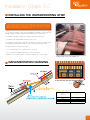
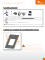
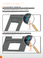
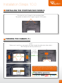
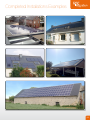
GSE INTEGRATION
INSTALLATION MANUAL
Photovoltaic mounting system
for partial or complete roof covering
MCS
CERTIFICATE BBA 0156
V 10.2
WWW.GSEINTEGRATION.COM
Contents
STEP BY STEP
Presentation of system
p.4
Contents of kit
GSE Integration mounting plates
p.5
p.6 - 7
Tools required for installation
p.8
Implementation prescription
p.9 - 11
GSE Integration Installation steps
p.12 - 32
Maintenance
p.33
Assistance & Contact
p.34
Our Certifications
p.35
Examples of completed installations
p.36 - 37
3
Presentation of system
GSE INTEGRATION IN ROOF SYSTEM
The GSE Integration system is used to install modules on all types of roofing, (curved tiles, mechanical, flat,
slates), on new buildings or buildings being renovated.
The system may be installed in portrait format or in landscape format, with a specific mounting plate for
each format, on both small installations (less than 3 kWp) and large roofs (several hundred kWp).
The GSE Integration system may be installed on wood or metal structures and mounted on battens or
lathing. It can also be mounted directly on common rafters and can be installed on slopes between 15°
and 50°.
The GSE Integration system is guaranteed for 10 years, provided the installation recommendations given
below are respected. The system does not require much maintenance, except for regular cleaning of the
solar panels.
4
Contents of kit
Tools required for installation p. 8
Dimensions of Photovoltaic field on the roof p. 18
ASSEMBLY ACCESSORIES
2
1
3
Flashings
4
5
6
7
8
9
10
Mounting Plates
11
12
13
14
Waterproofing
15
ASSEMBLY ACCESSORIES
16
FLASHINGS
1. Stainless Steel Screw 6.5 x 60mm + EPDM
4. Flashing Hooks
Washer
5. Left and Right Top Flashings + Screw 4.8x25mm
2. Cellular EPDM Joint 21x25mm or 23x45mm
6. Top Center Flashing
3. 2014 Single and double renforceer clamps
7. Aluminum Pop Rivet
8. Top Corner Piece (For top Center Flashing)
9. Lateral Flashing + Screw 4.8x25mm
17
MOUNTING
PLATES
WATERPROOFING
15. Waterproofing Strip
11. Screw 6.5x60mm
+ EPDM Washer
16- Precompressed Seal Rool 20x40mm
12. GSE Portrait Plate
17. Roof Underlay Screen
13. GSE Landscape Plate
14. Lef tand Right Wedge
10. Top Flashing Junction
5
Mounting plate 1.0
PHOTOVOLTAIC PANELS - LANDSCAPE FORMAT
Upper mounting plate PV
Panel Support
Upper mounting plate PV
Panel Support
Water Drainage
Guide
Photovoltaic panel mounting
plate and guide
Clamp
Fixation
Zone
Mounting point on
structure, min. 6x
Clamp
Fixation
Zone
Photovoltaic panel mounting
plate and guide
Cable outlet
Water Drainage
Zone
Reference Fixation Point : DO NOT PRE-DRILL
Fixation Point needing pre-drilling
LANDSCAPE PLATE REFERENCE + MODULE SIZES
MODULES TOLERANCE
Graduated
overlapping zone
Height Tolerance
6
Width Tolerence
Photovoltaic panel support
REF.
Height (mm)
Width (mm)
1640 / 990-1001
952-1032
1641-1629
1650 / 990-1001
952-1032
1651-1639
1660 / 990-1001
952-1032
1661-1649
1670 / 990-1001
952-1032
1671-1659
1675 / 990-1001
952-1032
1676-1664
1680 / 990-1001
952-1032
1681-1669
1575 / 1082
1042-1122
1576-1564
1559 / 1046-1082
1042-1122
1560-1548
1580 / 808
768-848
1581-1569
Mounting plate 1.1
PHOTOVOLTAIC PANELS - PORTRAIT FORMAT
Upper mounting plate PV
Panel Support
Photovoltaic panel mounting
plate and guide
Cable outlet
Clamp
Fixation
Zone
Water Drainage
Guide
Mounting point on
structure, min. 6x
Clamp
Fixation
Zone
Water Drainage
Zone
Photovoltaic panel
support
Fixation Point needing pre-drilling
Reference Fixation Point :
DO NOT PRE-DRILL
Photovoltaic panel mounting
plate and guide
PORTRAIT PLATE REFERENCE + MODULE SIZES
MODULES TOLERANCE
Graduated
overlapping zone
Height Tolerance
REF.
Height (mm)
Width (mm)
1640 / 992
1600-1680
991-980
1640 / 1001
1600-1680
1002-989
1559 / 1046
1535-1615
1047-1037
1575 / 1069
1535-1615
1070-1058
1575 / 1082
1535-1615
1083-1071
1580 / 808
1540-1608
809-797
Width Tolerence
7
Tools required for installation
CHALK LINER
SCREWDRIVER
HAMMER
PLATE SHEAR
Adjustable torque necessary
DRILL BITS
POP RIVET PLIER
• WOOD AND METAL DRILL BIT ø 10 mm
• 6 PAN BIT ø 8 mm
MEASURING TAPE – WHITE MARKER OR PENCIL
8
Implementation prescription 1.0
ROOF FRAME / WIND ZONE CORRELATION
12 ° to 50 ° normal site (catеgorie IIIa) 2 roof slopes
Battens thickness
min board width Battens thickness
min board width Zone 4
min board width Zone 3
Battens thickness
Zone 2
min board width Zone 1
Battens thickness
The indicated values in the tables below apply only for wind
zones 1 through 4, and for an altitude inferior to 900 meters.
15
22
27
40
22
27
40
40
40
22
27
40
30
210
110
100
100
150
100
100
130
100
150
120
100
150
15
22
27
40
22
27
40
40
40
22
27
40
30
260
120
100
100
200
120
100
130
100
150
120
100
160
15
22
27
40
22
27
40
40
40
22
27
40
30
220
150
100
100
220
140
100
130
100
150
120
100
200
15
22
27
40
22
27
40
40
40
22
27
40
30
240
170
110
100
250
170
100
130
100
150
120
100
220
40
100
40
100
40
120
40
130
15
22
27
40
22
27
40
40
40
22
27
40
30
40
200
130
100
100
200
130
100
130
100
150
120
100
180
100
15
22
27
40
22
27
40
40
40
22
27
40
30
40
220
160
110
100
160
160
100
130
100
150
120
100
160
180
120
15
22
27
40
22
27
40
40
40
22
27
40
30
40
260
180
120
100
180
180
100
140
100
160
130
100
180
140
15
22
27
40
22
27
40
40
40
22
27
40
30
40
300
210
150
100
210
150
100
160
120
150
120
100
200
160
15
22
27
40
22
27
40
40
40
22
27
40
30
40
200
140
100
100
150
140
100
130
100
130
100
100
140
120
15
22
27
40
22
27
40
40
40
22
27
40
30
40
250
170
120
100
170
170
100
130
100
150
120
100
160
130
15
22
27
40
22
27
40
40
40
22
27
40
30
40
280
160
140
100
200
200
100
150
100
180
140
100
200
150
22
27
40
22
27
40
40
40
22
27
40
30
40
160
100
100
230
150
100
180
120
250
160
100
250
140
150
Main roof wall 10M height
Note Size in mm
Battens spacing ≤ 600 spacing trusses or rafters
600 ≤Battens spacing ≤ 900 spacing trusses or rafters
Battens spacing ≤ 1500 metal trusses
Battens spacing ≤ 1500 (1) Battened frame Battens spacing ≤ 1500 (1) Metal or wood frame
Side edge 10M height
Battens spacing ≤ 600 spacing trusses or rafters
600 ≤Battens spacing ≤ 900 spacing trusses or rafters
Battens spacing ≤ 1500 metal trusses
Battens spacing ≤ 1500 (1) Battened frame Battens spacing ≤ 1500 (1) Metal or wood frame
Angle 10M height
Battens spacing ≤ 600 spacing trusses or rafters
600 ≤Battens spacing ≤ 900 spacing trusses or rafters
Battens spacing ≤ 1500 metal trusses
Battens spacing ≤ 1500 (1) Battened frame Battens spacing ≤ 1500 (1) Metal or wood frame
(1):
Layout of the woods in the direction of the slope
9
Implementation prescription 2.0
GSE INTEGRATION MECHANICAL RESISTANCE
(PASS'INNOVATION N°2013-221)
TESTED WIND ZONES
Depression calculation N / m2 (Pa) calculated in the case of slopes plans
(V65 with following rules amending No. 2)
Table 1.1 - Slopes Plans - Rolled ribbed steel wood and derived products - New Construction - Buildings closed
Height
(m)
Position
Normal
Exposed
Normal
Exposed
Normal
Exposed
Normal
Exposed
Normal
Exposed
Main wall
Side Edge
Angles
Main wall
Side Edge
Angles
Main wall
Side Edge
Angles
Main wall
Side Edge
Angles
Main wall
Side Edge
Angles
x4
Reinforced clamps 2014 (resistance 1860 Pa - security coef. 1.5)
x6
Reinforced clamps 2014 (resistance 3460 Pa - security coef. 1.5)
Roof zones - rule V65
Wind zones - rule V65
10
On a building 15m high, the entire roof surface
can be used.
Implementation prescription 3.0
DILATATION
(example: GSE Landscape Plate Réf. 1660/992)
Fixed
Reference
Points
Dilatation of the Clamp
fixation points
mm
Dilatation of the mounting
plate fixation points
Fixed
Reference
Points
8mm on 4 points = 2mm/point
6mm on 3 points = 2mm/point
4mm on 3 points = 1,33mm/point
4mm on 4 points = 1mm/point
The dilatation between
the mounting plate and
the wood batten requires a pre-drilling
of the plate with a ø 10 mm drill bit at
the points where you will be fixing your
Dilatation of the Clamp fixation points
Dilatation of the mounting plate fixation points
clamps as well as the points where
you will be fixing the mounting plate on
the roof structure.
11
Installation Steps 1.0
COVER PREPARATION
Info : Please remember to download our layout calculator at: www.gseintegration.com, to help you determine the exact
field quotes.
Intermodule
of 5mm advised
Field Height: ±
intermodule of 5mm + module height x number of modules
+ 150 mm (for waterproofing strip on tile)
+ 320 or 200 mm
Field Height
Field width:
± 60mm + intermodule of 30mm
+ module width x number of modules + (2 x 150 mm)
Field Height
Calculate the PV Field Size
Landscape installation
Portrait Installation
• Make sure to uncover 200mm on each side for the lateral flashings.
• In case of Top flashings use, make sure to uncover at least 320mm above the top module.
1) Remove the cover elements on the above-calculated width.
2) Take out an extra row of tiles on the left and on the right (2 rows for slate, or flat tiles)
3) Also remove the cover elements on the calculated height above.
4) Take out one row of tile on the top part (2 rows for slate or flat tiles)
Photovoltaic field
calculated above
Slate roof :
2 extra rows taken out.
12
Photovoltaic field
calculated above
Tile roof :
1 extra row taken out.
Installation Steps 2.0
LATHING PREPARATION ACCORDING THE THE MOUNTING PLATE
Lathing for Portrait Installation – Traditional Roof Structure (cf. Tables on P.9)
43 cm
25 cm
123 cm
90 cm
180 cm
159 cm
212 cm
195 cm
260 cm
328 cm
292 cm
350 cm
EXAMPLE BELOW: SPACING BETWEEN BATTENS 60cm – LATHING 27x100mm – MODULE 1675mm in Length)
100mm to
120mm: minimum covering
with the
waterproofing
strip
LATHING FOR PORTRAIT INSTALLATION – INSTALLATION ON PAN STEEL (cf. tables on P.9)
EXAMPLE BELOW: SPACING BETWEEN BATTENS 60cm – LATHING 27x100mm – MODULE 1675mm in Length
Existing batten:
Spacing of 150 cm
added intermediate
wooden batten :
If spacing is > 150 cm
18 cm
85 cm
103,5 cm
13
Installation Steps 2.1
LATHING PREPARATION ACCORDING TO THE MOUNTING PLATE
26 cm
74 cm
100mm to
120mm:
minimum
covering
with the
waterproofing strip
54 cm
113 cm
92 cm
193 cm
176 cm
155 cm
127 cm
215 cm
Lathing for Portrait Installation – Traditional Roof Structure (cf. Tables on P.9)
EXAMPLE BELOW: SPACING BETWEEN BATTENS 60cm – LATHING 27x100mm – MODULE 1001mm in Length
LATHING FOR LANDSCAPE INSTALLATION – INSTALLATION ON PAN STEEL (cf. tables on P.9)
EXAMPLE BELOW: SPACING BETWEEN BATTENS 60cm – LATHING 27x100mm – MODULE 1675mm in Length
Existing batten:
Spacing of 150 cm
added intermediate
wooden batten :
If spacing is > 150 cm
18,5 cm
Remember to verify with the module manufacturer’s installation
notice the compatibility of the module with the fixation clamps
on the small side.
14
40 cm
85 cm
128,5 cm
150 cm
169 cm
Installation Steps 3.0
INSTALLING THE WATERPROOFING STRIP
1.1) In the case of a shallow slope or thick roofing elements (e.g. curved tiles) or very
shaped roofing elements, in order to avoid standing water, install two 2 wood planks
dimensioned according to following table (on the entire field width and of sufficient
thickness to allow water to be evacuated correctly).
1.2 ) Unroll the waterproofing strip (self adhesive preferably) on the prepared
lathing, making sure that it exceeds the PV field by 20cm on each side.
1.3) Fold back the upper edge of the waterproofing strip around 2cm
1.4) Fold back the right and left ends in the same way.
1.5 ) Firmly press the waterproofing strip onto the first row of tiles, pressing it down
smoothly and carefully (ensure that you don’t create any water trap zones)
The strip should cover the pan as follows :
- 12 cm for tiles that are very curved (curve of over 3cm)
- 10cm for flat tiles or slightly curved (curve of less than 3cm)
Installation on curved tiles requires a waterproofing strip 45 to 56 cm wide.
Superior edge have to be folded 2cm
IMPLEMENTATION DRAWING
(1.4)
Roof
slope (°)
Battens width
implementation (mm)
12 tot 16
17 tot 19
20 tot 24
25 tot 50
220
180
150
120
15
Installation Steps 4.0
INSTALLING THE FIRST ROW OF MOUNTING PLATES
1.1) Using the chalk liner, mark a line on the waterproofing
strip, parallel to the battens and 15 cm to 20 cm below the
top edge of the waterproofing strip.
The plate will cover 12 cm.
1.2) Position the first mounting plate in the bottom righthand corner of the uncovered area, aligned with the chalk
liner mark. Install the mounting plate.
Screw the mounting plate using the 2 central fixing points that
do not need pre-drilling (see mounting recommendations
on pages 6, 7, 13 and 14).
1.3) Place your second mounting plate next to the first one, making sure that they interlock. Same for the mounting plates on the
second row and the rows above, etc.
Mounting plate wave
1.4) Using the pencil or white marker, mark the future
clamp fixation points, on the mounting plates waves, according to
the lathing that has been implemented. Once the plates have been
installed, these marks will allow you to fix the clamps at the right position,
and aligned. (see fixation recommendations on pages 9 to 17).
Tip : : To determine the placement of fixation of the clamps
on the module, you can use the module cells as marks.
INSTALLATION THE FOLLOWING ROWS OF MOUNTING PLATES
The mounting plates above need to overlap the
mounting plates below all the way until in contact
with the dedicated stops.
The overlap hence will be of 12 to 16cm
depending on your module height. (p. 6/7)
16
Installation Steps 5.0
PRE-DRILLING OF THE MOUNTING PLATES WITH A DRILL BIT OF ø 10 mm
Clamp Fixation on high
point of the mounting plate.
Stainless Steel Screw 6.5x60mm
+ EPDM Joint
+ cellular EPDM foam
Fixation of the mounting
plate on the roof structure
Stainless Steel Screw 6.5x60mm
+ EPDM Joint
Fixation and preparation of the mounting plates
EPDM Washer ø 16mm
Pre-drilling
ø 10mm
Cellular EPDM foam
21x25mm
EPDM Washer
ø 16mm
Pre-drilling
ø 10mm
Stainless Steel
Screw ø 6,5mm
Mounting plate to roof structure fixation drawing
(only 4 of the 6 fixation points)
Stainless Steel Screw 6.5x60mm + EPDM Joint
Stainless Steel
Screw
ø 6,5mm
Clamp fixation drawing on the mounting plate
Stainless Steel Screw 6.5x60mm + EPDM Joint
+ cellular EPDM foam
Make sure to correctly position the screw at the center of the pre-drilled hole in order to ensure
waterproofing longevity. A tolerance has been calculated to this effect during the product design phases.
17
Installation Steps 5.1
REMINDER
During the preparation of the roof structure, it is necessary to install a roof underlay screen, up to the gutter.
DIRECTION OF THE APPLICATION
Please remember to overlap the mounting
plates, 12cm to 16 cm, depending on
your module size.
(You can adjust this overlap with the
graduation on the mounting plate – (cf.
“GSE Intgration Plates adjustment”
Section).
The mounting plates are preferably
installed from right to left but can also be
installed left to right (make sure the plates
are properly interlocked)
18
Installation Steps 6.0
CLAMPS FIXATION
(draw 2) 1
2
3
14
The clamps are to be fixed only on the mounting plate edge (draw 2)
Attach the clamps (3) using the screws to this effect (1) making sure to stick the EPDM foam (2) between the clamp and
the mounting plate to ensure waterproofness.
For single clamps fixation, make sure to position the left and right wedges (14) correctly inside the edge of
the mounting plates.
Make sure the wedges are positioned before the lateral flashings.
Make sure to fix the clamps on the wood battens. It is imperative to stick the EPDM foam (2) under the clamp (between
the mounting plate and the clamp).
FIXING THE CLAMPS ON THE MOUNTING PLATES
2 or 3 clamps
per wave
2 or 3
clamps
per wave
The use of the various clamps varies according to the wind
zones, but needs also to respect the PV module manufacturer’s
recommendations.
The majority of PV modules have a resistance to wind depression of 2400Pa.
The reinforced clamps being valid all the way to 3400Pa, it is important to
have the manufacturer’s authorization to go over 2400 Pa (cf Table p.10)
19
Installation Steps 6.1
NOTE
Make sure you interlock the mounting plates correctly in order to ensure proper waterproofing of the
system.
View of 4 interlocked mounting plates
Double clamps
fixation
3
x2
4
1
20
1
Stick the cellular EPDM foam under the clamp
2
Tighten the screw once and take it out
3
Repeat
4
cellular
EPDM
Tighten the clamp in its position
Clamps attachment
points on the PV panel
after screwing.
Installation Steps 7.0
GSE PLATES ADJUSTMENT
The GSE Integration Plates are adjustable according to your panel size.
In order to adjust the GSE plates, use the graduations on the plate. The graduation vary from 0 to 40 mm.
After having screwed all the mounting plates at the 2 center points, you can start preparing your ø 10
mm drill bit. And pre-drill all the other holes on the plate, that means 4 pre-drills on top of the 2 fixing points
already made.
GSE PORTRAIT MOUNTING PLATE
Ex:
the H1640-80mm x W992mm can fit a panel
1640 to 1680 mm high, and 992mm wide
Graduated
overlapping zone
GSE LANDSCAPE MOUNTING PLATES
Ex: the 1640mm Wide x 992-1032 mm long plate can fit a panel
1640 mm high and 992 to 1032mm wide
Graduated
overlapping zone
*Cf. Tables on p.6-7
21
Installation Steps 7.1
ADJUSTMENT EXAMPLES
(1650 MM MODULES IN PORTRAIT)
GSE PORTRAIT MOUNTING PLATE (H1640-80mm X W992mm)
For a H1650 mm panel, position the plate at 10mm back
For a H1660 panel = 20 mm back
Graduated
overlapping zone
GSE LANDSCAPE MOUNTING PLATE (W1640mm X H992-1032mm)
For a panel H1002, position the plate at 10mm back
For a panel H1012 = 20mm back
Graduated
overlapping zone
22
Installation Steps 8.0
WEDGES POSITIONNING
The 2014 Version of the GSE Intgration System requires
positioning wedges on the lateral parts of the field.
These wedges are to be placed under the plate wave at the
edge, right under where the clamps will be fixed.
• Please note that there is a left and a right wedge
• The wedge will be drilled with the plate and lateral flashing,
before fixing the single clamp.
23
Installation Steps 9.0
INSTALLATION OF THE LATERAL FLASHINGS
1.1) Position the lateral flashings overlapping the waves on the right
and left edges of the integration system.
1.2) Use a screw 4.8x25mm at the junction of 2 lateral flashings to
fix them together.
1.3) Then, position the single clamp where you marked the mounting
plates. Mark the pre-drilling point on the lateral flashing.
1.4) Pre-drill a 10mm hole, making sure you go through the lateral
flashing, the plate and the wedge.
Overlapping of 15 cm
The flashings interlock each other, with the top part over the bottom part to allow proper water drainage
1) Open the lateral clip over 10 to 15 cm (lower lateral flashing).
2) Interlock the upper lateral flashing on the lower one, then re-close the clip
3) Fix the lateral flashing to the roof structure using the flashing hooks (5)
Upper lateral flashing to be interlocked
on the lower one.
Open the lateral clip over 10 to 15 cm.
Position and install the upper skirt and clip,
and close the clip.
Fix the lateral flashing on the battens using the flashing hooks (5).
The overlap of one lateral flashing on top of the other needs to be 15 cm
24
Installation Steps 10.0
INSTALLING THE PHOTOVOLTAIC PANELS
Place the first row of panels on the mounting plates.
The panel is installed on the 2 upper supports on the plate.
PASSING THE CABLES (1)
Note:
Cables must transit from one panel to the next through the dedicated cable outlets :
Slot through the central protection pad
1
(1 & 2)
Passing
the cables
2
If you are using optimizers or micro-inverters, you can
fix them in the center hole of the mounting plate, on the
visible wood battens without risking the module to press
on your equipment.
OPTIMIZERS
OR
MICROINVERTER
Compatibility approved for :
25
Installation Steps 10.1
PASSING THE CABLES
Panels should be connected horizontally when installed in portrait format.
The panel can be installed upright or inverted.
INSTALLATION FOR
PANELS OF MINIMUM
40MM THICKNESS
INSTALLATION
FOR PANELS
OF THICKNESS
between 31mm
and 50mm
ELECTRICALLY EARTHING THE PANELS
The photovoltaic panel should be earthed through the dedicated hole in alloy frame
of the photo-voltaic panel
BLOCK DIAGRAM FOR SINGLE STRING WIRING
Good wiring practice is to limit the INDUCED loop lengths
Chassis earthing
Inverter DC input
AC BOX
INVERTER
DC BOX
Panels earthed directly on the
house earthing stake.
Earthing terminals
26
Installation Steps 10.2
MOUNTING THE PHOTOVOLTAIC PANELS
1/ For fixation of the PV Panel to the plate you will have to use one of the two possible clamps (cf. p.14 or below)
2/ use the pre-drilled holes (1.4 p.24) in the lateral flashings and the wedges to position your 3 clamps per panel side. ???
3/ Before fixing the clamps, stick the EPDM Joint under the clamps to ensure waterproofing. Use the 6.5x60mm screw supplied.
4/ The double clamps fix the panels 2 by 2 and align to the single clamps.
5/ The single clamps are fixed at the edge of the PV Field, align to the double clamps and are position over the wedges that are
under the plate wave.
BE CAREFUL TO SCREW THE ELEMENTS
WITH THE RIGHT FORCE
Too weak
correct
Too strong
Diagram of clamps positioning
For landscape fixation, please refer to the
PV panel manufacturer’s notice.
Single Clamps
Double Clamps
TESTED WIND ZONES
Height
(m)
Position
Normal
Exposed
Normal
Exposed
Normal
Exposed
Normal
Exposed
Normal
Exposed
Main wall
Side Edge
Angles
Main wall
Side Edge
Angles
Main wall
Side Edge
Angles
Main wall
Side Edge
Angles
Main wall
Side Edge
Angles
x4
Reinforced clamps 2014 (resistance 1860 Pa - security coef. 1.5)
x6
Reinforced clamps 2014 (resistance 3460 Pa - security coef. 1.5)
3
*Cf table p. 9-10
27
Installation Steps 11.0
INSTALLING THE TOP FLASHINGS
1/ The tile or zinc covering the top flashings should be at least of 15 cm. In case of a shallow slope or a tile
of high curve, the covering should be more.
2/ On slate, a 10cm covering is enough.
Last tile
Last tile
10 cm 5 cm
10 cm
PREPARATION OF THE TOP CORNER PIECE (FOR TOP CENTER FLASHING)
Top Corner
Piece
Pop Rivets (8)
Use the pop rivets (8) supplied with the kit and mount the corner bead on the central edge joiner. Each hole corresponds to a panel
thickness. The first hole is used when installing the central edge joiner with panels 50 mm thick, the second hole for 45 mm panels,
the third hole for 40 mm panels and the last hole for 35 and 31mm panels.
31
35
45
40
50
31
35
45
40
50
31
35
45
Top Corner piece facial view
28
40
50
31
35
45
40
50
Installation Steps 11.1
MINIMUM ROOF SLOPE FOR FLASHINGS INSTALLATION
ACCORDING TO THE THICKNESS OF THE PV PANELS.
MINIMUM TOP FLASHING PITCH : 5°
Top Flashing
Length
Sensor Height
Pitch
Flat Section
PANEL THICKNESS
MINIMUM ROOF SLOPE (°)
MINIMUM ROOF SLOPE (%)
35
40
46
50
14
15
16
17
31%
33%
37%
39%
A batten may be
installed
Length
Pitch
Sensor Height
Flat Section
H paneel
Slope (°)
Slope (%)
Batten X (mm)
Slope (°)
Slope security (°)
A 5° margin is of course taken into account.
This information is only a guide.
Care should be taken to ensure that all roofing regulatory requirements are met.
29
Installation Steps 11.2
Installation of top flashings
1/ Place the top center flashing, having made sure first that
the top corner piece is fixed to the top center flashing (see
p.28). To do so, clip the module in the space created by the
top corner piece, and then fix the top center flashing piece to
the roof structure using the flashing hooks.
Sensor Height
(1)
Add 2 lines of PU adhesive between the
junction and the top center flashing.
(1)
2/ Ensure that 2 top flashing pieces are connected together
with the “Top Flashing Junction” piece.
(2)
Apply two vertical beads of PU adhesive to ensure
waterproofing.
3/ Place the Top left and top right flashing pieces on top of the
top center flashings and the lateral flashings.
100
mm
(3)
100
mm
Once the top corner flashings are positioned, use the
4.8x25mm screws supplied.
4.8x25mm
screw
Apply two vertical beads of PU adhesive to ensure
waterproofing.
(4)
4/ The top corner flashing can be adjusted to the panel
thickness by cutting.
Can be cut to fit
(5)
5/ In a portrait installation the top corner piece (for top flashings)
needs to be cut at the edge of the mounting plate.
30
45
35
50
40
31
45
35
50
40
45
35
31
Top corner piece cut
50
40
31
45
35
50
40
31
Installation Steps 11.3
Replacing Top Flashings with a lead
waterproofing strip
Lead waterproofing strip is warrantied for 30 years by its manufacturer. It applies like any waterproofing strip or any lead
strip. It can be welded as well like traditional zinc.
1/ Unroll the lead waterproofing strip, ensuring that the top of the
plate is covered and that the strip is under the tile by at least 15cm.
It is hence necessary to adapt the width of the waterproofing strip to
respect this rule.
2/ Fold back 2 cm of a the waterproofing strip at the top.
3/ 2. Unroll the precompressed seal on the entire width of the
installation, making sure it connects with the precompressed
seal on the lateral flashings.
• On slopes that are less than 20 degrees, it is imperative to use a
lead waterproofing strip at least 45cm wide.
• ATTENTION : For slate or flat tiles, put the slate or tiles over the waterproofing
strip without covering the GSE plate wave. Otherwise some tiles would be
lifted by the plate wave compared to the tiles next to them.
Plate waves
covering
31
Installation Steps 12.0
INSIDE AND OUTSIDE ANGLE
For specific configurations of inside and outside angles, a waterproofing strip is necessary. This installation
process answers to roofing regulations. However a few rules need to be followed :
Outside Angles / "T" angle
• Position the lateral flashing
--- Put the GSE plate over the waterproofing strip,
making sure that the overlap is at least 12cm and that
the strip goes over the all the way to the GSE plate
edge wave
•
Inside Angle / "L" angle
--- Position the waterproofing strip on the top of the
•
plate, as well as over the plate wave that form the
inside angle.
• Position the lateral flashing from the top of the
waterproofing strip to the panels support of the GSE
plate beneath
Make sure to cut the waterproofing strip at the top of the
plate wave to avoid a tear over time.
Stop the waterproofing strip
at the top of the plate wave
32
Risk of tear
Installation Steps 13.0
INSTALLING THE PRECOMPRESSED SEAL
(recommended size: W 20 mm / H 40 mm)
1/ Unroll the precompressed seal on the
lateral flashings all the way to the bottom of the
waterproofing strip.
The junction between 2 joints needs to be tight.
Precompressed seal
2/ Unroll the precompressed seal on the entire length
of the top flashing.
m
2c
m
mi
c
n. 3
3/ The precompressed seal needs to be put at 2cm from the edge of the
lateral flashings. You also need a minimum of 3cm from the edge of the
mounting plate in order to have proper water drainage.
33
Installation Steps 13.1
PV FIELD INSTALLATION FINAL STEPS
Put back the rows of tiles or slate on top of the lateral flashings and on top of the top flashings, covering
enough of the flashings.
34
Maintenance
INSPECTION
It is important to check once per year whether any leaves or other elements have penetrated under the
photovoltaic system. Such elements can be blown out using a compressed air blower. Do not use solvent to
clean the mounting plates, which are in polypropylene.
It is recommended that you offer your customers a maintenance contract, which would include an annual
inspection of : generation, electrical system, panels, panel mounting plates, mountings, precompressed
seals, waterproofing strip.
REPLACING A MODULE
1/ Power off the PV INSTALLATION.
2/ Remove the clamps from the panel to be replaced.
3/ Disconnect the earthing connection and disconnect it from the string.
4/ Take out the panel that needs to be changed and replace it with the new one.
5/ Connect the new panel to the earth and reconnect it to the string.
6/ put back the clamps.
The equipotential connection must be maintained.
35
Assistance & contact
training
Trainings can be organized with your
distributor.
Please contact your distributor for further
information.
TECHNICAL ASSISTANCE
TECHNICAL ASSISTANCE IS AVAILABLE WITH YOUR DISTRIBUTOR
OR FROM MONDAY TO FRIDAY AT THE CONTACT INFORMATION BELOW.
16 QUAI GUSTAVE FLAUBERT 76380 CANTELEU
Tél. 02 32 10 77 60
Mail : [email protected]
36
Our Certifications
•
“PASS INNOVATION VERT” Nr. 2013-221 – Module ZN Shine ( from oct. 2013 to oct. 2015)
THE FRENCH ETN CERTIFICATION AUTHORIZES THE INSTALLATION OF GSE INTEGRATION IN
PORTRAIT AND LANSCAPE PROVIDED THAT THE MODULE MANUFACTURER ACCEPTS THE
MODULE FIXATION ON THE SMALL SIDE.
•
ETN INDICE 0 - BT130003
Validated by Alpes-contrôles :
*Solarworld Sunmodule + (Mono) – portrait
*Soluxtec Powerslate (Mono) – portrait/landscape
*Sillia 60P (Poly) – portrait
*BenQ PM245 (Poly) – portrait
*QCells G3 pro (Poly) – portrait/landscape (1400 Pa)
•
•
ETN INDEX 1
*Solarworld Sunmodule Poly & SunProtect
*Sunpower 3XX (Mono)
*BenQ SunForte (Mono)
*Soluxtec Das module (Poly-Mono)
*Aléo S19 HE (Mono)
*Csun 60P / 60M (Poly-Mono)
*Solarwatt (Poly-Mono-Vision)
*LG (Poly, Mono, Mono X)
FireTest :
*BROOF T1 – Approved (Belgian, Deutsch, and German markets)
*BROOF T3 – Approved (French market)
*BROOF T4 – Approved (British market)
• Mechanical resistance, UV, humidity, weather tests available at www.gseintegration.com
• New certification CERTISOLIS Sunpower / BenQ SunForte / GSE Intégration in process
• Test EN12179 - Approved
• MCS012 - Approved
37
Completed Installations Examples
38
Completed Installations Examples
39
GSE INTEGRATION is a GROUPE SOLUTION ENERGIE
patented development program
www.segroup.fr
Your distributor :
GROUPE SOLUTION ENERGIE
155-159 rue du Docteur Bauer. 93400 SAINT OUEN - Tél. : +33(0)1 70 32 08 00 - Fax : +33(0)1 70 32 08 01- email: [email protected]