1
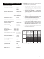
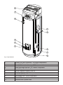
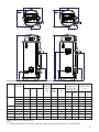
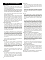
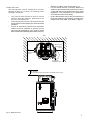
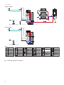
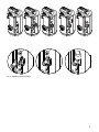
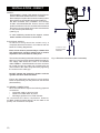
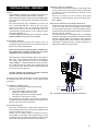
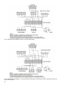
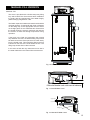
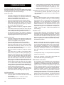
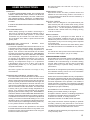
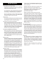
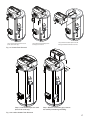
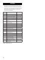
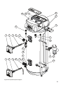
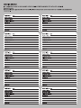
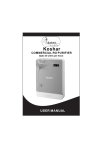
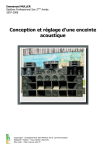
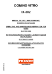
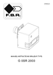
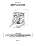
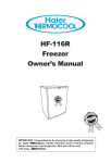
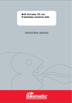
Coral Aquanox Installation Manual
Thermal Store Direct & Indirect Water Heaters
Installation & Servicing Instructions
Pack Contents
• Coral Aquanox vented water heater incorporating immersion heater(s) & thermal controls
• Visual discharge indicator
• Compression nuts & olives
• Immersion heater spanner
• Installation & servicing instructions
• Guarantee card
• Blending valve insulation kit
IMPORTANT
Please read & understand all these instructions before commencing installation.
Please leave this manual with the user for future reference.
1
CONTENTS
INTRODUCTION............................................................2
TECHNICAL SPECIFICATION.......................................3
INSTALLATION GENERAL............................................6
MANUAL FILL VERSION.............................................13
COMMISSIONING.......................................................14
USER INSTRUCTIONS...............................................15
MAINTENANCE...........................................................16
PERFORMANCE.........................................................18
FAULT FINDING & SERVICING..................................21
SPARES.......................................................................22
HEAT LOSS.................................................................24
ENVIRONMENTAL INFORMATION.............................24
COMMISSIONING CHECK LIST.................................26
SERVICE RECORD.....................................................27
GUARANTEE...............................................................28
TECHNICAL SUPPORT...............................................28
THE BENCHMARK SCHEME
Benchmark places responsibilities on both
manufacturers and installers. The purpose is
to ensure that customers are provided with the
correct equipment for their needs, that it is installed,
commissioned and serviced in accordance with the
manufacturer’s instructions by competent persons
and that it meets the requirements of the appropriate
Building Regulations. The Benchmark Checklist can
be used to demonstrate compliance with Building
Regulations and should be provided to the customer
for future reference.
Installers are required to carry out installation,
commissioning and servicing work in accordance with
the Benchmark Code of Practice which is available
from the Heating and Hotwater Industry Council who
manage and promote the Scheme.
Visit www.centralheating.co.uk for more information.
IMPORTANT NOTE TO USER: PLEASE REFER TO
THE USER INSTRUCTIONS SECTION ON PAGE 15
FOR IMPORTANT INFORMATION WITH RESPECT TO
THE BENCHMARK SCHEME
2
INTRODUCTION
Thank you for purchasing an Elson Thermal Store.
The thermal store is manufactured in the UK to the
highest standards and has been designed to meet all
the latest relevant safety specifications.
The Elson Coral Aquanox thermal store is an Open
Vented Hot Water only Thermal Store (HWTS).
The stored energy in a Hot Water only Thermal Store
is only used indirectly via a natural convection hot
water heat exchanger for producing instantaneous
domestic hot water. The storage vessel of an open
vented thermal store is open to atmosphere and it uses
primary water to store thermal energy.
The thermal store is a purpose designed vented water
heater. Hot water is delivered at mains water pressure.
The unit has a stainless steel vessel, which ensures
an excellent standard of corrosion resistance. The
outer casing is a combination of resilient thermoplastic
mouldings and plastic coated corrosion proofed
steel sheet. All products are insulated with CFC free
polyurethane foam to give good heat loss performance.
(see Table 5, page 24)
This appliance complies with the requirements of the
CE marking directive and is KIWA approved to show
compliance with Water Regulations.
NOTE: Prior to installation the unit should be stored
in an upright position in an area free from excessive
damp or humidity.
IMPORTANT:
THE THERMAL STORE MUST BE INSTALLED AND
COMMISSIONED BY A COMPETENT PERSON.
PLEASE READ AND UNDERSTAND THESE
INSTRUCTIONS BEFORE INSTALLING THE
THERMAL STORE. FOLLOWING INSTALLATION
AND COMMISSIONING, THE OPERATION OF THE
THERMAL STORE SHOULD BE EXPLAINED TO THE
USER AND THESE INSTRUCTIONS LEFT WITH
THEM FOR FUTURE REFERENCE.
THIS APPLIANCE IS NOT INTENDED FOR THE
USE BY PERSONS (INCLUDING CHILDREN) WITH
REDUCED PHYSICAL, SENSORY OR MENTAL
CAPABILITIES, OR LACK OF KNOWLEDGE AND
EXPERIENCE, UNLESS THEY HAVE BEEN GIVEN
SUPERVISION OR INSTRUCTION CONCERNING
THE USE OF THE APPLIANCE BY A PERSON
RESPONSIBLE FOR THEIR SAFETY.
CHILDREN MUST BE SUPERVISED TO ENSURE
THEY DO NOT PLAY WITH THE APPLIANCE.
TECHNICAL SPECIFICATION
OPERATIONAL SUMMARY
Total storage volume (VT)
120ltrs
150ltrs
175ltrs
210ltrs
Maximum mains pressure
0.5MPa (5 bar)
Heat Loss
1.75kWh/24h
2.02kWh/24h
2.23kWh/24h
2.49kWh/24h
120ltr
150ltr
175ltr
210ltr
Store thermostat settings
12-85°C
+4/-6°C
Overheat thermostat settings
96°C+2/-5°C
Maximum working pressure for
DHW heat exchanger
0.5MPa (5 bar)
Pressure Loss (FDHW)
0.5 bar at 12.6ltrs/min
DHW Volume
(Volume of water >40°C
75°C store temp at 12.6ltrs/min)
LIMITATIONS
The Thermal Store water heater should not be used
in association with any of the following:
•
Solid fuel boilers or any other boiler in which the
energy input is not under effective thermostatic
control, unless additional and appropriate safety
measures are installed.
•
Ascending spray type bidets or any other class
1 back syphonage risk requiring that a type A air
gap be employed.
•
Steam heating plants unless additional and
appropriate safety devices are installed.
•
Situations where maintenance is likely to be
neglected or safety devices tampered with.
•
Water supplies that have either inadequate pressure
or where the supply may be intermittent.
•
In areas where the water consistently contains a
high proportion of solids, e.g. suspended matter
that could block the blending valve, unless
adequate filtration can be ensured.
•
In areas where the water supply contains chloride
levels that exceed 200mg/l.
120ltrs 115ltrs
150ltrs 123ltrs
175ltrs 146ltrs
210ltrs 168ltrs
DHW Outlet temperature setting
55°C (TMV2 adj 35-60°C)
Type
Indirect
Maximum working pressure for
Primary heat exchanger
1.0MPa
(10 bar)
Thermal rating of Primary
heat exchanger
11kW
Pressure Loss (FPHE)
0.2 bar at 15ltrs/min
Ingress Protection
IPX2
Electrical rating
3kW @ 240V ac
Weight when full
See Table 1
Direct
Nominal
Model
Capacity
Reference
(litres)
Weight
of unit
empty
(Kg)
Weight
of unit
full
(Kg)
120ti
120
43
170
150ti
150
53
210
175ti
175
57
239
210ti
210
67
291
120td
120
38
165
150td
150
48
205
175td
175
52
234
210td
210
63
287
Table 1: Unit weights
3
6
5
4
7
8
3
2
1
9
10
11
Fig. 1 Key Features
1
2
3
4
5
6
7
8
9
10
11
4
Primary Coil Flow Connection - 3/4”/22mm compression
Primary Coil Return Connection - 3/4”/22mm compression
Electrical Connection Housing - IPX2
Visual Discharge Indicator - 22 x 28mm compression
Feed & Expansion Header Tank
Feed & Expansion Header Tank Lid
Blending Valve Insulation Cover
Hot Outlet (TMV2) - 22mm compression
Cold Supply Inlet - 22mm compression
DHW Coil Drain
Thermal Store Cylinder Drain
650
650
Ø 580
620
620
Ø 580
27°
310
310
450
(375 120LTR)
360
316
450
(375 120LTR)
B
B
C
A
A
47°
Fig. 2 Dimensions and performance (Auto-fill versions shown)
Type
Direct
Indirect
Model
Reference
Dimensions (mm)
A
B
C
Total
Storage
Volume
(VT)
Coil Rating (kW)
Hot
Water
Coil
Primary
Coil
Hot Water
Capacity (ltrs)
Hot Water
Capacity (ltrs)
Store
Temp
75°C
Store
Temp
85°C
Store
Temp
75°C
Store
Temp
85°C
(volume of water
drawn off >40°C)
(v40°C)
120td
1111
516
-
120
35
11
115
144
157
202
150td
1274
626
724
150
35
11
123
154
166
215
175td
1450
801
900
175
33
11
146
190
180
264
210td
1677
1033
1127
210
33
11
168
216
213
299
120ti
1111
516
-
120
35
11
115
144
157
202
150ti
1274
626
-
150
35
11
123
154
166
215
175ti
1450
801
-
175
33
11
146
190
180
264
210ti
1677
1033
-
210
33
11
168
216
213
299
Table 2: Dimensions and performance
Note:
1. Thermal store tested in conformance with the HWA Performance Specification for Thermal Stores
5
INSTALLATION GENERAL
WATER SUPPLY
Bear in mind that the mains water supply to the
property will be supplying both the hot and cold water
requirements simultaneously.
It is recommended that the maximum water
demand is assessed and the water supply checked
to ensure this demand can be satisfactorily met.
Note: A high mains water pressure will not always
guarantee high flow rates.
Wherever possible the mains supply pipe should be
22mm. We suggest the minimum supply requirements
should be 0.15MPa (1.5 bar) pressure and 20 litres
per minute flowrate. However, at these values outlet
flow rates may be poor if several outlets are used
simultaneously. The higher the available pressure and
flow rate the better the system performance.
HARD WATER AREAS
The building regulations L1A: New dwellings/L1B:
Existing dwellings and the requirements set out in
the Domestic Building Services Compliance Guide
specify that ‘Where the mains total water hardness
exceeds 200 parts per million, provision should be
made to treat the feed water to water heaters and the
hot water circuit of combination boilers to reduce the
accumulation of limescale.’
To maintain the performance of the Thermal Store
water heater and in order to comply with this regulation
the hardness of the mains water should be checked
by the installer and if necessary fit a proprietary scale
reducer or water softener to the cold water supply,
refer to the manufacturers instructions for installation
for guidance.
Please consult the local water authority for additional
advice on water quality if required.
INHIBITOR
The use of a corrosion inhibitor is recommended
to prolong the performance and efficiency of the
Thermal Store. Checking the concentration of
corrosion inhibitor in the Thermal Store is essential,
dose appropriately according to the size of the
Thermal Store volume in accordance with the inhibitor
manufacturer’s guidelines.
Please refer to BS 7593:2006 Code of practice for
treatment of water in domestic hot water central
heating systems.
PIPE FITTINGS
The cold feed is made via 22mm copper pipe spigot.
Primary coil pipe fittings are made via 22mm
compression fittings directly to the unit. The fittings
are threaded 3/4”BSP male parallel, should threaded
pipe connections be required.
6
COLD FEED
A 22mm cold water supply is recommended, however,
if a 15mm (1/2”) supply exists, which provides sufficient
flow, this may be used (although more flow noise may
be experienced).
A stopcock or servicing valve should be incorporated
into the cold water supply to enable the Thermal
Store and its associated controls to be isolated and
serviced.
OUTLET
The hot water outlet is a 22mm compression fitting
located at the thermostatic mixer valve (TMV2). Hot
water distribution pipework should be 22mm pipe with
short runs of 15mm pipe to terminal fittings such as
sinks and basins. Pipe sizes may vary due to system
design.
The Thermal Store can be used with most types of
terminal fittings. It is advantageous in many mixer
showers to have balanced hot and cold water supplies.
In these instances a balanced pressure cold water
connection should be placed between the cold water
supply inlet and Thermal Store cold feed connection.
A minimum distance of 2 mtrs to the first cold water
draw off-take must be observed (see Fig. 4, page 8).
Outlets situated higher than the thermal Store will
give outlet pressures lower than that at the heater, a
10m height difference will result in a 0.1MPa (1 bar)
pressure reduction at the outlet. All fittings, pipework
and connections must have a rated pressure of at least
0.5MPa (5 bar) at 80°C.
DOMESTIC HOT WATER BACK EXPANSION
During a heating cycle the expansion of water in
the DHW heat exchanger must be accommodated.
Expansion back into the mains may not always be
possible. (For example, a double check valve may be
fitted in the mains supply). If required the minimum
expansion vessel size recommended is 1ltr. This must
be fitted upstream of the DHW exchanger as shown in
the schematic. (Figure 4, Page 8)
Any method or product used for accommodating the
expansion must comply with the Water Regulations
and relevant standards.
MANUAL HANDLING GUIDANCE
The appliance exceeds the recommended weight for
a one man lift. Upon installation it will be necessary
to get assistance when lifting or manoeuvring the
product into place. Use of mechanical lifting aids may
be necessary.
DO NOT LIFT THE APPLIANCE BY THE ATTACHED
PIPEWORK OR ANCILLARY COMPONENTS.
SITING THE UNIT
The Thermal Store must be vertically floor mounted.
Although location is not critical, the following points
should be considered:
•
•
•
The Thermal Store should be sited to ensure
minimum dead leg distances, particularly to the
point of most frequent use.
Avoid siting where extreme cold temperatures will
be experienced. All exposed pipe work should be
insulated.
Access to associated controls and immersion
heaters must be available to provide for the
servicing and maintenance of the system. Where
these controls are installed against a wall a minimum
•
•
distance of 300mm must be left (see Fig. 3).
For the autofill versions a minimum distance of
225mm must be left free above the unit in order to
comply with the access requirements of the water
regulations. This requirement is for replacement
of the ball float valve if necessary.
Ensure that the floor area for the Thermal Store is
level and capable of permanently supporting the
weight when full of water. (see Table 1, Page 3)
Wall
Min 300mm
maintenance
access
Min 300mm
maintenance
access
Hot Outlet
Adjustable 180°
Min 225mm
Access for float valve maintenance (Auto-fill version only)
Fig. 3: Siting the Unit
7
Schematics
Indirect model
P
2 metres is required for
expansion in pipework
before nearest cold
draw-off
Gas
AAV
CWS
Where expansion down the mains is not possible install an
expansion vessel with a capacity not less than 1000ml
Direct model
2 metres is required for
expansion in pipework
before nearest cold
draw-off
CWS
Where expansion down the mains is not possible install an
expansion vessel with a capacity not less than 1000ml
Key
Pump
Lock Shield Valve
Flow Setter
Single Check Valve
Drain Cock
Automatic Bypass Valve
Combined Isolation & Check
Valve with Thermometer
Thermostatic Radiator Valve
Radiator Lock Shield Valve
Aqua
P
Aqua Stat
Room Stat
Pressure Gauge Assembly
Double Check Valve
Strainer
Safety Valve
Filling Loop
Thermostatic Mixing Valve
Double Reg. Valve
T & P Valve
Flexible Connection
Flow Meter
Stop Cock
AAV
Pressure Reducing Valve
Angle pattern Drain Cock
Automatic Air Vent
Isolation Valve
Expansion Vessel
2 Port Motorised Valve
Programmer
Air Separator
S
8
Anti-Gravity Dip
Tundish
Safety Discharge Vessel
Temperature Sensor
Immersion Heater
The hydraulic schematics within this document are for guidance only and do not constitute system design. Some components may not be detailed for clarity purposes.
Fig. 4: Technical Hydraulic Schematics
AGD
Fig. 5: Blending Valve Insulation
9
INSTALLATION - DIRECT
SAFETY
DISCONNECT FROM THE MAINS ELECTRICAL
SUPPLY BEFORE REMOVING ANY COVERS.
Never attempt to replace the immersion heater(s) other
than with the recommended immersion heater(s).
DO NOT bypass the thermal cut-out(s)
in any circumstances. Ensure the two male
spade terminations from the combined thermostat and
thermal cut-out are pushed firmly onto the terminations
on the element plate assembly.
(See Fig. 6)
In case of difficulty contact service support; contact
details available at the back of this booklet.
ELECTRICAL SUPPLY
All electrical wiring should be carried out by a
competent electrician and be in accordance with the
latest I.E.E Wiring Regulations.
Each circuit must be protected by a suitable fuse
and double pole isolating switch with a contact
separation of at least 3mm in both poles.
The immersion heater(s) should be wired in accordance
with Fig 6. The immersion heater(s) MUST be earthed.
The supply cable should be 1.5mm2 3 core flexible
cable H05BN4-F to BS EN 50525-2-21:2011 and must
be routed through the cable grip provided with the
outer sheath of the cable firmly secured by tightening
the screws on the cable grip.
DO NOT operate the immersion heaters until the
cylinder has been filled with water.
Ensure the thermostat and thermal cut-out sensing
bulbs are pushed fully into the pockets on the element
plate assembly.
PLUMBING CONNECTIONS
Direct Thermal Stores require the following pipework
connections.
• Cold water supply to and from inlet.
• Outlet to hot water draw off points.
• Discharge pipework from visual indicator.
All connections are 22mm compression. However,
3/4”BSP parallel threaded fittings can be fitted to the
primary coil connections if required.
10
N
L
1.5mm² 3 Core
sheathed cable
H05BN4-F
Fig. 6: Electrical connections (direct schematic)
INSTALLATION - INDIRECT
SAFETY
DISCONNECT FROM THE MAINS ELECTRICAL
SUPPLY BEFORE REMOVING ANY COVERS.
Never attempt to replace the immersion heater(s) other
than with the recommended authorised immersion
heater(s).
DO NOT bypass the thermal cut-out in
any circumstances. Ensure the two male
spade terminations from the combined thermostat
and thermal cut-out are pushed firmly onto the
corresponding terminations on the element plate
assembly. (See Fig. 7)
In case of difficulty contact service support; contact
details available at the back of this booklet.
ELECTRICAL SUPPLY
All electrical wiring should be carried out by a
competent electrician and be in accordance with the
latest I.E.E Wiring Regulations.
PRIMARY CIRCUIT CONTROL
A motorised valve MUST be fitted on the primary flow
to the cylinder heat exchanger and wired in series with
the indirect control thermostat and thermal cut-out
fitted to the unit.
Primary circulation to the Thermal Store heat
exchanger must be pumped; gravity circulation WILL
NOT WORK.
SPACE AND HEATING SYSTEMS CONTROLS
Controls will be required ensure the safe operation
of the unit within the central heating system. Other
controls will be necessary to control the space heating
requirements and times that the system is required to
function, see Fig. 9 below.
The Thermal store is compatible with most heating
controls, examples of electrical circuits are shown
in Figs. 8 and 9 (Page 12). However, other systems
may be suitable, refer to the controls manufacturers’
instructions, supplied with the controls selected, for
alternative system wiring schemes.
Each circuit must be protected by a suitable fuse
and double pole isolating switch with a contact
separation of at least 3mm in both poles.
Element Connections
The immersion heater should be wired in accordance
with Fig 7. The immersion heater MUST be earthed.
The supply cable should be 1.5mm2 3 core flexible
cable H05BN4-F to BS EN 50525-2-21:2011 and must
be routed through the cable grip provided with the
outer sheath of the cable firmly secured by tightening
the screws on the cable grip.
DO NOT operate the immersion heaters until the
cylinder has been filled with water.
Ensure the thermostat and thermal cut-out sensing bulbs
are pushed fully into the pockets on the element plate
assembly.
PLUMBING CONNECTIONS
Indirect Thermal Stores require the following
pipework connections.
• Cold water supply to and from inlet.
• Outlet to hot water draw off points.
• Discharge pipework from visual indicator.
• Connection to the primary circuit.
All connections are 22mm compression. However,
3/4”BSP parallel threaded fittings can be fitted to the
primary coil connections if required.
1
Indirect control
wiring
2
3
L
N
1.5mm² 3 Core
sheathed cable
H05BN4-F
Fig. 7: Electrical connections (indirect schematic)
BOILER SELECTION
The boiler should have a control thermostat and non
self-resetting thermal cut-out and be compatible with
thermal storage water heaters.
Where use of a boiler without a thermal cut-out is
unavoidable a “low head” open vented primary circuit
should be used. The feed and expansion cistern head
above the Thermal Store should not exceed 2.5m.
11
Fig. 8: Schematic wiring diagram - Basic 2 x 2 port valve system
Fig. 9: Schematic wiring diagram - 3 port mid position valve system. N.B. Must be used in conjunction with 2 port
zone valve supplied
12
MANUAL FILL VERSION
MANUAL FILL
The store is provided with a flexible temporary filling
loop which MUST be disconnected after installation
to comply with the requirements of the Water Supply
(Water Fittings) Regulations 1999.
The feed & expansion header tank water level should be
checked regularly. If required fill with clean cold water
via the filling loop to the appropriate level as shown
on the sight glass. Do not overfill the tank. Ensure that
the header tank lid is securely replaced, this reduces
the amount of water lost through evaporation during
operation.
If the level in the feed and expansion tank should
drop between services, the flexible filling loop should
be attached and the valve opened to let water slowly
into the header tank. This should be filled to the line
indicated on the side of the units header section. The
filling loop should then be disconnected.
In the event of leak the only water that can be lost is
the water held within the Thermal Store at that time.
Fig. 10: Manual fill Version
Fill level of header tank with internal indicator
Fig. 11: Autofill Water Level
Upper Limit
Lower Limit
Filling loop
Fig. 12: Manual fill Water Level
13
COMMISSIONING
FILLING THE UNIT WITH WATER
Ensure that all fittings and immersion heaters are correctly
fitted and tightened. An immersion heater key is provided
to aid tightening the immersion heater(s)
AUTO FILL UNIT
• Check all connections for tightness including the
immersion heater(s). An immersion heater key
spanner is supplied for this purpose.
• Ensure that both drain cocks are CLOSED.
• Open a hot tap furthest from the Thermal Store.
• Open the mains stop cock to fill the unit. When
water flows from the tap, allow to run for a few
minutes to thoroughly flush through any residue,
dirt or swarf, then close the tap.
• Open successive hot taps to purge the system
of air.
• The Thermal Store will continue to fill via the ball
valve located in the feed & expansion header tank.
This will stop when the cylinder store is full.
• Set the level of water in the cistern by adjusting
the height of the ball float using the internal water
height gauge as shown in Fig.11 page 13.
MANUAL FILL UNIT
• Check all connections for tightness including the
immersion heater(s). An immersion heater key
spanner is supplied for this purpose.
• Ensure that both drain cocks are CLOSED.
• Open a hot tap furthest from the Thermal Store.
• Open the mains stop cock to fill the unit. When
water flows from the tap, allow to run for a few
minutes to thoroughly flush through any residue,
dirt or swarf, then close the tap.
• Open successive hot taps to purge the system
of air.
• The ‘filling loop’ is used for introducing mains
water into the cylinder for filling and topping up
purposes. The ‘filing loop’ has an isolating valve
at each end. To introduce water into the system,
undo one of these valves completely and gently
open the other valve to control the rate of flow of
water into the cylinder. Introduce water until the
sight gauge on the feed & expansion tank is level
with the bottom fill line as shown in Fig.12 page
13. Turn both valves off fully. The temporary filling
loop should be disconnected after installation to
comply with the requirements of the Water Supply
(Water Fittings) Regulations 1999
• The feed & expansion header tank water level
should be checked regularly. If required fill with
clean cold water via the filling loop to ‘top up’.
SYSTEM CHECKS
Upon commissioning a competent engineer should:
• Check all water connections for leaks and rectify
as necessary.
• Check water pressure – maximum 5.0bar
• Check operation of all service valves
14
•
Check operation of the blending valve and test that
the water temperature (hot flow mix) is at 55°C
when the store temperature is operating at 75°C.
• Check operation of the immersion heater
thermostats and settings.
Complete the service record at the back of the
commissioning booklet provided to comply with
the manufacturers guarantee and Benchmark
requirements.
DIRECT UNIT
Switch on electrical supply to the immersion heater(s)
and allow the cylinder to heat up to normal working
temperature (75°C recommended, approximately
graduation 4 on the thermostat). If necessary the
temperature can be adjusted by inserting a flat
bladed screwdriver in the adjustment knob on top of
the immersion heater thermostat and rotating. The
adjustment range 1 to 5 represents a temperature
range of 37°C to 85°C. Check the operation of
thermostat(s).
INDIRECT UNIT
Fill the indirect (primary) circuit following the boiler
manufacturer’s commissioning instructions. To ensure
the cylinder primary heat exchanger is filled, the 2 port
motorised valve should be manually opened by moving
the lever on the motor housing to the MANUAL setting.
When the primary circuit is full return the lever to the
AUTOMATIC position.
Switch on the boiler, ensure the programmer is set to
Domestic Hot Water and allow the cylinder to heat up
to a normal working temperature (75°C recommended,
approximately graduation 5 on the thermostat).
If necessary the temperature can be adjusted by
inserting a flat bladed screwdriver in the adjustment
knob and rotating. The minimum thermostat setting
is 12°C.
The adjustment range 1 to 5 represents a temperature
range of 37°C to 85°C.
Check the operation of the indirect thermostat and
motorised valve during the heating cycle.
BENCHMARK LOG BOOK
On completion of the installation and commissioning
procedures detailed in this manual the Benchmark
“Installation, Commissioning and Service Record Log,
pages 26 and 27 should be completed and signed off
by the competent installer or commissioning engineer
in the relevant sections. The various system features,
location of system controls, user instructions and
what to do in the event of a system failure should be
explained to the customer. The customer should then
countersign the BenchmarkTM commissioning checklist
(page 26) to accept completion. The Service Record
should be filled in when any subsequent service or
maintenance operation is carried out on the product.
USER INSTRUCTIONS
WARNINGS
IF STEAM DISCHARGES FROM THE OVERFLOW
VISUAL INDICATOR SHUT DOWN THE BOILER
OR IMMERSION HEATER(S). DO NOT TURN OFF
ANY WATER SUPPLY. CONTACT A COMPETENT
INSTALLER FOR WATER HEATERS TO CHECK THE
SYSTEM.
IF A FAULT IS SUSPECTED CONTACT A COMPETENT
INSTALLER.
FLOW PERFORMANCE
When initially opening hot outlets a small surge in
flow may be noticed as pressures stabilise. This is
quite normal with hot water systems. In some areas
cloudiness may be noticed in the hot water. This is
due to aeration of the water, is quite normal and will
quickly clear.
TEMPERATURE CONTROLS – DIRECT UNIT
IMMERSION HEATER(S)
A combined adjustable thermostat and thermal cut-out
is provided for each immersion heater. The thermostat
is factory set to give a water storage temperature of
approx. 75°C. Access to the thermostat can be made
by opening the immersion heater cover - DISCONNECT
THE ELECTRICAL SUPPLY BEFORE OPENING
THE COVER(S). Temperature adjustment is made
by inserting a flat bladed screwdriver in the slot on
the adjustment spindle on top of the thermostat and
rotating. The adjustment range 1 to 5 represents
a temperature range of 37°C to 85°C (75°C will be
approximately position 4). If in any doubt contact a
competent electrician.
DO NOT bypass the thermal cut-out(s) in any
circumstances.
TEMPERATURE CONTROLS - INDIRECT UNIT
The Thermal Store units are fitted with an indirect control
thermostat and thermal cut-out. These controls must be
wired in series with the motorised zone valve to interrupt
the flow of primary water around the heat exchanger coil
when the control temperature has been reached. The
controls are located within the terminal housing along
with the immersion heater thermostat. The thermostat
is factory set to give a water storage temperature of
approx. 75°C. Access to the thermostat can be made
by opening the terminal housing cover - DISCONNECT
THE ELECTRICAL SUPPLY BEFORE OPENING THE
COVER. Temperature adjustment is made by inserting
a flat bladed screwdriver in the adjustment spindle and
rotating. The minimum thermostat setting is 12°C. The
adjustment range 1 to 5 represents a temperature range
of 37°C to 85°C (75°C will be approximately position 4).
If in any doubt contact a competent electrician.
An immersion heater is also provided for use should
the indirect heat source be shut down for any reason. The
immersion heater control temperature is set using the
immersion heater thermostat.
DO NOT bypass the thermal cut-out(s) in any
circumstances.
OPERATIONAL FAULTS
Operational faults and their possible causes are
detailed in the Fault Finding section of this book. It
is recommended that faults should be checked by a
competent installer.
ELECTRIC TARIFFS
Direct units are designed to use predominantly low
tariff electricity but with a boost switch during normal
tariff periods. The thermal store is designed to heat
water to 75°C. At this temperature performance is
maintained with minimal heat loss, keeping running
costs to a minimum.
BOOST ELEMENT
During periods of prolonged hot water draw-off or
during cold weather conditions the use of the ‘boost’
element may be more common. If the inlet cold water
temperature is very low more energy will be required
to heat the store.
The boost element will ensure hot water delivery when
the indirect heat store is not available for any reason.
HOLIDAY
It is safe to turn off the power to the Thermal Store and
shut off the water supply if you go on holiday.
THE BENCHMARK SCHEME
Elsy & Gibbons is a licensed member of the Benchmark
Scheme which aims to improve the standards of
installation and commissioning of domestic heating
and hot water systems in the UK and to encourage
regular servicing to optimise safety, efficiency and
performance.
Benchmark is managed and promoted by the Heating
and Hotwater Industry Council. For more information
visit www.centralheating.co.uk.
Please ensure that the installer has fully completed the
Benchmark Checklist (Page 26) of this manual and that
you have signed it to say that you have received a full
and clear explanation of its operation. The installer is
legally required to complete a commissioning checklist
as a means of complying with the appropriate Building
Regulations (England & Wales).
All installations must be notified to Local Area
Building Control either directly or through a
Competent Persons Scheme. A Building Regulations
Compliance Certificate will then be issued to the
customer who should, on receipt, write the
Notification Number on the Benchmark Checklist.
This product should be serviced regularly to optimise
its safety, efficiency and performance. The service
engineer should complete the relevant Service Record
on the Benchmark Checklist after each service.
The Benchmark Checklist may be required in the event
of any warranty work.
15
MAINTENANCE
MAINTENANCE REQUIREMENTS
Thermal store hot water systems have a continuing
maintenance requirement in order to ensure safe
working and optimum performance.
The maintenance checks described below should be
performed by a competent person on a regular basis,
e.g. annually to coincide with boiler maintenance.
After any maintenance, please complete the relevant
Service Interval Record section of the Benchmark
Checklist on Page 27 of this document.
INSPECTION
The immersion heater boss can be used as an access
for inspecting the cylinder internally. Ensure the unit is
drained before removal of immersion heater.
DE-SCALING THE DHW EXCHANGER
The hot water heat exchanger may be de-scaled in the
field by a qualified technician using a high pressure
de-scaling pump and suitable acidic de-scaling
chemical (e.g. Fernox DS3). The store must be cooled
to between 30 and 40°C before commencing the descaling. This must be carried out by a skilled person
because of the specialist equipment needed.
DE-SCALING IMMERSION HEATER(S)
Before removing the immersion heater(s) the unit
must be drained. Ensure the water, electrical supply and
boiler are OFF before draining. Attach a hosepipe to
the drain cock having sufficient length to take water to
a suitable discharge point below the level of the unit.
Open a hot tap close to the unit and open the drain
cock to drain the unit.
DIRECT UNITS
Switch on electrical supply to the immersion heater(s)
and allow to heat up to normal working temperature
(75°C recommended, approximately graduation 4 on
the thermostat). If necessary the temperature can
be adjusted by inserting a flat bladed screwdriver in
the adjustment knob on top of the immersion heater
thermostat and rotating. The adjustment range 1 to 5
represents a temperature range of 12°C to 68°C. Check
the operation of thermostat(s) and that no water has
issued from the expansion relief valve or temperature/
pressure relief valve during the heating cycle.
INDIRECT UNITS
Open the cover(s) to the immersion heater housing(s)
and disconnect wiring from immersion heater(s)
thermostat(s). Remove thermostat by carefully pulling
outwards. Remove thermostat capillary sensors from
the pockets on the immersion heater. Unscrew
immersion heater backnut(s) and remove immersion
heater from the unit. A key spanner is supplied with
the cylinder unit for easy removal/tightening of the
immersion heater(s). Over time the immersion heater
gasket may become stuck to the mating surface. To
16
break the seal insert a flat bladed screwdriver into one
of the pockets on the immersion heater and gently
lever up and down.
Carefully remove any scale from the surface of the
element(s). DO NOT use a sharp implement as
damage to the element surface could be caused.
Ensure sealing surfaces are clean and seals are
undamaged, if in doubt fit a new gasket
(part number 95 611 822).
Replace immersion heater(s) ensuring the lower
(right angled) element hangs vertically downwards
towards the base of the unit. It may be helpful to
support the immersion heater using a round bladed
screwdriver inserted into one of the thermostat pockets
whilst the backnut is tightened. Replace thermostat
capillaries into pocket. Replace the immersion heater
thermostat by carefully plugging the two male spade
terminations on the underside of the thermostat head
into the corresponding terminations on the element.
Rewire, check, close and secure immersion heater
housing cover(s).
RE-COMMISSIONING
Check all electrical and plumbing connections are
secure. Close the drain cock. With a hot tap open, turn
on the cold water supply and allow unit to refill. DO NOT
switch on the immersion heater(s) or boiler until the
unit is full. When water flows from the hot tap allow it
to flow for a short while to purge air and flush through
any disturbed particles. Close the hot tap and then
open successive hot taps in the system to purge any
air. When completely full and purged check the system
for leaks. The heating source (immersion heater(s) or
boiler) can then be switched on.
INHIBITOR
The use of a corrosion inhibitor is required to maintain
the performance and cylinder guarantee of the
Thermal Store. Checking the concentration of the
corrosion inhibitor in the Thermal Store is essential
to prevent corrosion. Dose appropriately according to
the size of the volume in accordance with the inhibitor
manufacturer’s guidelines.
Please refer to BS 7593:2006 Code of practice for
treatment of water in domestic hot water central
heating systems.
Step 1: Drain feed & expansion tank
(note: drain tank only)
Step 2: Release feed & expansion
tank pipe connections
Step 3: Remove feed & expansion tank
fixing bolt & slide forwards to remove
Fig. 13: Header Tank Removal
Step 1: Drain feed & expansion tank
(note: drain tank only)
Step 2: Release connection pipe, remove
rear tank by unhooking and lifting
Fig. 13a: 210litre Header Tank Removal
17
PERFORMANCE
DHW Performance of a thermal store
Coral Aquanox 120ltr
60
DHW outlet temperature (°C)
50
40
75°C
85°C
30
20
10
0
0
20
40
60
80
100
120
140
160
180
200
Draw-off volume (l)
Fig. 14: 120ltr Hot Water Performance
DHW Performance of a thermal store
Coral Aquanox 150ltr
60
DHW outlet temperature (°C)
50
40
75°C
85°C
30
20
10
0
0
20
40
60
Fig. 15: 150ltr Hot Water Performance
18
80
100
120
Draw-off volume (l)
140
160
180
200
DHW Performance of a thermal store
Coral Aquanox 175ltr
60
DHW outlet temperature (°C)
50
40
75°C
85°C
30
20
10
0
0
20
40
60
80
100
120
140
160
180
200
220
240
Draw-off volume (l)
Fig. 16: 175ltr Hot Water Performance
DHW Performance of a thermal store
Coral Aquanox 210ltr
60
DHW outlet temperature (°C)
50
40
75°C
30
85°C
20
10
0
0
20
40
60
80
Fig. 17: 210ltr Hot Water Performance
100
120
140
160
180
200
220
240
260
280
Draw-off volume (l)
19
Pressure Loss Characteristics of DHW heat exchanger
Coral Aquanox
0.90
0.80
Pressure Loss (bar)
0.70
0.60
0.50
0.40
0.30
0.20
0.10
0.00
0
6.3
9.45
12.6 (FDHW)
13.86
15.75
16.5
18.75
DHW flow rate (l/min)
Fig. 18: Pressure Loss Characteristics: DHW Exchanger
Pressure Loss Characteristics of a Primary heat exchanger
Coral Aquanox
0.40
0.35
Pressure Loss (bar)
0.30
0.25
0.20
0.15
0.10
0.05
0.00
0
7.5
11.25
15 (FPHE)
Primary flow rate (l/min)
Fig. 19: Pressure Loss Characteristics: Primary Heat Exchanger
20
FAULT FINDING & SERVICING
IMPORTANT
• After servicing, complete the relevant Service
Interval Record section of the Benchmark Checklist
located on page 27 of this document.
• Servicing should only be carried out by competent
persons in the installation and maintenance of
water heating systems.
• Any spare parts used MUST be authorised Elson
parts.
• Disconnect the electrical supply before removing
any electrical equipment covers.
• NEVER bypass any thermal controls or operate
system without the necessary safety controls.
• Water contained in the thermal store may be very
hot, especially following a thermal control failure.
Caution must be taken when drawing water from
the unit.
Fault
No hot water flow
SPARE PARTS
A full range of spare parts are available for the
Thermal Store (Table 4 Page 22). Refer to the technical
data label on the unit to identify the model installed
and ensure the correct part is ordered. You will need
to quote the serial number which is printed on the
data label.
FAULT FINDING
The fault finding chart (Table 3) will enable operational
faults to be identified and their possible causes
rectified. Any work carried out on the thermal store
and its associated controls MUST be carried out by a
competent installer. In case of doubt contact service
support (see contact details on back page).
Possible Cause
Mains water supply off
Remedy
Check and open stop cock/isolating valve
Direct immersion heater not switched on Check and switch on
Water from hot tap
is cold
Direct immersion heater thermal cut-out
has operated
Check, reset by pushing button on thermal cutout
Indirect programmer set to central heating only
Check, set to domestic hot water programme
Indirect boiler not working
Check boiler operation. If fault is suspected
consult boiler manufacturer’s instructions
Indirect thermal cut-out has operated
Check, reset by pushing button on thermal cutout
Check operation of indirect thermostat
Indirect motorised valve not connected
correctly
Check wiring and/or plumbing connections to
motorised valve
INTERMITTENTLY
The water level of the feed & expansion tank has
been set incorrectly.
Occasional small discharge is normal and is generally due to condensation.
Water discharges
CONTINUALLY
from overflow visual
indicator
Check the operation of the ball float valve,
inspect the float for leaks. Check the ball valve
seat for damage.
Isolate the ball float valve, if the water continues
to discharge there may be a leak in the internal
DHW heat exchanger coil.
Performance has
detiorated
GRADUALLY
Check for scale build up in the DHW heat exchanger
SUDDENLY
Check the operation of the blending valve.
Table 3: Fault Finding Chart
21
SPARES
The following comprehensive list of spare parts is
available for your Elson Thermal Store water heater.
Please refer to the rating label on the Elson Thermal
Store water heater before ordering to ensure the
correct spare is obtained
Item
Description
Number
1
Terminal cover
95 614 095
2
Immersion heater backnut
95 607 869
3
Immersion heater gasket
95 611 822
4
Immersion heater (Bent)
95 606 984
5
Immersion heater (Straight)
95 606 986
6
Direct thermostat & thermal
cut-out
95 612 057
7
Indirect thermostat &
thermal cut-out
95 612 058
8
6 Way terminal block
95 607 933
9
3 Way terminal block
95 607 932
10
Visual indicator
95 607 367
11
Tank fittings assembly
95 607 368
12
F&E tank boss 3/4"
95 607 369
13
Pipe fittings assembly
95 607 676
14
Thermostatic mixing valve
95 605 089
15
Blending valve cover
assembly (3pcs)
95 614 134
16
Copper float
95 607 677
17
Float valve
95 607 678
18
Feed & expansion tank lid
95 614 135
19
Grommet vent pipe
95 607 683
20
Immersion heater key
spanner (not shown)
95 607 861
21
Sight glass (not shown)
95 614 136
22
Motorised 2 port valve
(not shown)
95 605 049
Table 4: Spares Parts List
22
Part Number
16
18
19
17
12
11
11
1
2
5
6
3
11
12
9
10
3
1
2
4
6
7
8
14
15
13
Figure 20: Exploded Spares Diagram
23
HEAT LOSS
Nominal
Capacity
(Litres)
ENVIRONMENTAL
Standing Heat Loss
per day
(kWh/24h)
per year
(kWh/365d)
120
1.26
460.54
150
1.46
531.59
175
1.61
586.86
210
1.80
655.28
Table 5: Standing heat losses
DESIGN
To minimise heat loss, a 60mm thick void-free layer of
high-performance polyurethane foam fills the space
between the inner vessel and outer casing for maximum
insulation efficiency and compliancy with future Europeanwide legislation.
The Coral Aquanox is supplied with an innovative casing
which insulates the blending valve. The carefully injection
moulded one-piece insulation can be fitted after installation
for ease of plumbing.
The base is fully insulated and the unit stands on three
moulded feet to minimise heat loss to the supporting floor.
Immersion heaters and controls are fully integrated with
no large external bosses to radiate heat.
RECOMMENDATIONS
To minimise the standing heat loss it is recommended that
all exposed hot water pipework is insulated. This will keep
hot water hotter for longer and save energy.
24
Products are manufactured from many recyclable
materials. At the end of their useful life they should be
disposed of at a Local Authority Recycling Centre in order
to realise the full environmental benefits.
Insulation is by means of an approved CFC/HCFC free
polyurethane foam with an ozone depletion factor of
zero.
NOTES
25
26
27
Sales & Support
Guarantee
Servicing
Spares
On site service support including
parts and labour for 12 months from
date of installation. After the initial 12
months, a guarantee will apply for
a further four years for the stainless
steel inner vessel only. During this four
year period, in the event of a cylinder
leak, a replacement product will be
issued provided that the replacement
is carried out by one of our heateam
engineers, for which reasonable labour
charges will apply.
heateam
For all technical support, replacement
parts & service issues please contact:
heateam is BDR Thermea’s very own
service division. With us on your side,
you can be sure that your customers
are in the very best of hands. Totally
committed to quality and safety,
heateam is open 7 days a week, for
363 days a year, and offers:
Electric Water Heating Co.
2 Horsecroft Place, Pinnacles,
Harlow, Essex CM19 5BT
Tel: 0845 0553811
E-mail: [email protected]
•
Dedicated Trade Advice
Line - our helpful and qualified
specialists are always on hand
to help you with even the most
complex technical query.
SPD
Special Product Division, Units 9 & 10
Hexagon Business Centre,
Springfield Road,
Hayes, Middlesex UB4 0TY
Tel: 020 8606 3567
•
Installer Priority Call-Outs - our
280 strong team of specifically
trained expert heating engineers
covers the UK, no one is better
qualified to look after Elson’s
products for the duration of the
guarantee.
Parts Center
Tel: 0845 270 9800
www.partscenter.co.uk
The guarantee is valid provided that:
•
•
•
•
•
•
•
•
•
It has been correctly installed as
per the instructions contained
in the instruction manual and all
relevant Codes of Practice and
Regulations in force at the time of
installation.
The Benchmark Checklist
has been completed upon
commissioning and the
Benchmark Service Record is
completed for each service.
It has not been modified in any
way, other than by ELSON.
It has not been frost damaged.
It has not been tampered with
or been subjected to misuse or
neglect.
The fault is not scale related.
Within 60 days of installation the
user completes and returns the
certificate supplied along with the
proof of purchase to register the
product.
It has been installed in the United
Kingdom.
The fault is not caused by high
chloride levels in the water supply
or incorrect disinfection methods.
Maximum permissible chloride
level 200mg/l (PPM).
•
•
Fully Stocked Vans - a
nationwide fleet of vans, fully
stocked with spare parts meaning we can repair our
appliances on the first visit 95% of
call-outs.
Exclusive Service Plans heateam also offer Elson’s
customers a range of exclusive
annual service plans.
Opening Times: Monday-Friday 8am6pm, weekends and Bank Holidays*
8.30am-2pm.
Newey & Eyre
Specialists Products Division
Please contact your local branch
UK Spares Ltd
Tower Lane, Warmley,
Bristol BS30 8XT
Tel: 0117 961 6670
www.uk-spares.com
Advanced Water Company Ltd
Unit 5D, Enterprise Way, Vale Park,
Evesham, Worcestershire WR11 1GS
Tel: 01386 760 066
*excluding Christmas Day and New Year’s Day.
Simply call 0844 335 8819 or visit our
website at www.heateam.co.uk
Evidence of purchase and date
of supply may be required. The
guarantee is transferable. This
guarantee does not affect your
statutory rights.
Policy Statement
The policy of ELSON is one of
continuous product development
and, as such, we reserve the right to
change specifications without notice.
Elsy & Gibbons, Fifers Lane, Norwich, Norfolk NR6 6XB
T: 0844 335 8819
F: 0844 871 1528
E: [email protected]
W: elsonhotwater.co.uk
36006142_issue_01
28