1
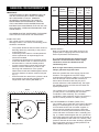
Zircon Installation Manual
Unvented Direct & Indirect Water Heaters
Installation & Servicing Instructions
Pack Contents
• Zircon unvented water heater incorporating immersion heater(s) & thermal controls
• Factory fitted temperature/pressure relief valve (set at 90°C / 1 Mpa (10bar))
• Cold water combination valve assembly
• Expansion vessel & mounting bracket
• Tundish
• 2 Port motorised valve (indirect models only)
• Compression nuts & olives
• Immersion heater spanner
• Installation & servicing instructions
• Guarantee card
IMPORTANT
Please read & understand all these instructions before commencing installation.
Please leave this manual with the customer for future reference.
1
CONTENTS
INTRODUCTION............................................................2
GENERAL REQUIREMENTS........................................3
INSTALLATION GENERAL............................................5
INSTALLATION DISCHARGE........................................7
INSTALLATION DIRECT...............................................11
INSTALLATION INDIRECT...........................................12
COMMISSIONING.......................................................14
MAINTENANCE...........................................................15
USER INSTRUCTIONS...............................................16
FAULT FINDING & SERVICING..................................17
SPARES.......................................................................18
HEAT LOSS.................................................................19
ENVIRONMENTAL INFORMATION.............................19
COMMISSIONING CHECK LIST.................................22
INTRODUCTION
The cylinder is a purpose designed unvented water
heater. The unit has a stainless steel inner vessel,
which ensures an excellent standard of corrosion
resistance. The outer casing is a combination of
resilient thermoplastic mouldings and plastic coated
corrosion proofed steel sheet. All products are
insulated with CFC free polyurethane foam to give
good heat loss performance. (see Table 6, page 19)
The unit is supplied complete with all the necessary
safety and control devices needed to allow
connection to the cold water mains. All these
components are preset and not adjustable.
This appliance complies with the requirements of the
CE marking directive and is Kiwa approved to show
compliance with Building Regulations (Section G3).
The following instructions are offered as a guide
to installation which must be carried out by a
competent plumbing and electrical installer in
accordance with Building Regulation G3, The
Building Standards (Scotland) Regulations 1990, or
The Building Regulations (Northern Ireland).
NOTE: Prior to installation the unit should be stored
in an upright position in an area free from excessive
damp or humidity.
SERVICE RECORD.....................................................23
GUARANTEE...............................................................24
TECHNICAL SUPPORT...............................................24
THE BENCHMARK SCHEME
Benchmark places responsibilities on both
manufacturers and installers. The purpose is to
ensure that customers are provided with the correct
equipment for their needs, that it is installed,
commissioned and serviced in accordance with the
manufacturer’s instructions by competent persons
and that it meets the requirements of the appropriate
Building Regulations. The Benchmark Checklist can
be used to demonstrate compliance with Building
Regulations and should be provided to the customer
for future reference.
Installers are required to carry out installation,
commissioning and servicing work in accordance
with the Benchmark Code of Practice which is
available from the Heating and Hotwater Industry
Council who manage and promote the Scheme. Visit
www.centralheating.co.uk for more information.
IMPORTANT NOTE TO USER: PLEASE REFER TO
THE USER INSTRUCTIONS SECTION ON PAGE 16
FOR IMPORTANT INFORMATION WITH RESPECT TO
THE BENCHMARK SCHEME
2
GENERAL REQUIREMENTS
IMPORTANT:
THIS APPLIANCE IS NOT INTENDED FOR THE
USE BY PERSONS (INCLUDING CHILDREN)
WITH REDUCED PHYSICAL, SENSORY
OR MENTAL CAPABILITIES, OR LACK OF
KNOWLEDGE AND EXPERIENCE, UNLESS
THEY HAVE BEEN GIVEN SUPERVISION OR
INSTRUCTION CONCERNING THE USE OF THE
APPLIANCE BY A PERSON RESPONSIBLE FOR
THEIR SAFETY.
CHILDREN MUST BE SUPERVISED TO ENSURE
THEY DO NOT PLAY WITH THE APPLIANCE.
SITING THE UNIT
The cylinder must be vertically floor mounted.
Although location is not critical, the following points
should be considered:
•
•
•
•
•
The cylinder should be sited to ensure minimum
dead leg distances, particularly to the point of
most frequent use.
Avoid siting where extreme cold temperatures
will be experienced. All exposed pipe work
should be insulated.
The discharge pipework from the safety valves
must have minimum fall of 1:200 from the unit
and terminate in a safe and visible position.
Access to associated controls and immersion
heaters must be available to provide for the
servicing and maintenance of the system.
Where these controls are installed against a wall a
minimum distance of 250mm must be left (see
Fig. 1).
Ensure that the floor area for the cylinder is level
and capable of permanently supporting the
weight when full of water. (see Table 1)
WALL
Min 250mm
Fig. 1: Siting the Unit
Nominal Weight of
Capacity unit full
(litres)
(Kg)
Weight
of unit
(Kg)
Type
Model
Reference
Indirect
120zi
120
147
27
150zi
150
182
32
170zi
170
204
34
210zi
210
250
40
250zi
250
294
44
300zi
300
352
52
120zd
120
144
24
150zd
150
178
28
170zd
170
201
31
210zd
210
247
37
250zd
250
289
39
300zd
300
349
49
Direct
Table 1: Unit weights
WATER SUPPLY
Bear in mind that the mains water supply to the
property will be supplying both the hot and cold
water requirements simultaneously.
It is recommended that the maximum water
demand is assessed and the water supply
checked to ensure this demand can be
satisfactorily met.
Note: A high mains water pressure will not
always guarantee high flow rates.
Wherever possible the mains supply pipe should
be 22mm. We suggest the minimum supply
requirements should be 0.15MPa (1.5 bar) pressure
and 20 litres per minute flowrate. However, at
these values outlet flow rates may be poor if
several outlets are used simultaneously. The higher
the available pressure and flow rate the better the
system performance.
The cylinder has an operating pressure of 0.35MPa
(3.5 bar) which is controlled by the cold water
combination valve assembly. The cold water
combination valve assembly can be connected to a
maximum mains pressure of 1.6MPa (16 bar).
Min 250mm
OUTLET/TERMINAL FITTINGS (TAPS, ETC.)
The cylinder can be used with most types of terminal
fittings. It is advantageous in many mixer showers
to have balanced hot and cold water supplies. In
these instances a balanced pressure cold water
connection should be placed between the 2 pieces
of the cold water combination valve assembly (see
Fig. 2). Outlets situated higher than the cylinder will
give outlet pressures lower than that at the heater, a
10m height difference will result in a 0.1MPa (1 bar)
pressure reduction at the outlet. All fittings, pipework
and connections must have a rated pressure of at
least 0.6MPa (6 bar) at 80°C.
3
LIMITATIONS
The cylinder should not be used in association with
any of the following:
• Solid fuel boilers or any other boiler in which the
energy input is not under effective thermostatic
control, unless additional and appropriate safety
measures are installed.
• Ascending spray type bidets or any other class
1 back syphonage risk requiring that a type A air
gap be employed.
• Steam heating plants unless additional and
appropriate safety devices are installed.
• Situations where maintenance is likely to be
neglected or safety devices tampered with.
• Water supplies that have either inadequate
pressure or where the supply may be
intermittent.
• Situations where it is not possible to safely pipe
away any discharge from the safety valves.
• In areas where the water consistently contains a
high proportion of solids, e.g. suspended matter
that could block the strainer, unless adequate
filtration can be ensured.
• In areas where the water supply contains
chloride levels that exceed 250mg/l.
OPERATIONAL SUMMARY
Maximum mains pressure Operating pressure Maximum design pressure Expansion vessel charge pressure
Expansion relief valve setting T&P relief valve setting
Maximum primary circuit pressure
(indirect only)
Pressure drop (Primary coil) Storage capacity
Weight when full
1.6MPa (16 bar)
0.35MPa (3.5 bar)
0.6MPa (6 bar)
0.35MPa (3.5 bar)
0.6MPa (6 bar)
90-95°C/1.0MPa (10 bar)
1.0MPa (10 bar)
0.02MPa (0.2 bar)
see Table 1
see Table 1
Indirect Models in conformance with BS EN 12897:2006
4
INSTALLATION GENERAL
PIPE FITTINGS
All pipe fittings are made via 22mm compression
fittings directly to the unit. The fittings are threaded
3/4”BSP male parallel, should threaded pipe
connections be required. COLD FEED
A 22mm cold water supply is recommended, however,
if a 15mm (1/2”) supply exists, which provides sufficient
flow, this may be used (although more flow noise
may be experienced).
A stopcock or servicing valve should be incorporated
into the cold water supply to enable the cylinder and
its associated controls to be isolated and serviced.
COLD WATER COMBINATION VALVE ASSEMBLY
The 2-piece cold water combination valve assembly
(see Fig. 2) can be located anywhere on the cold
water mains supply prior to the expansion vessel
(see Fig. 6 Page 10) but the two pieces do not have
to be installed together.
The pressure reducing valve incorporates the
pressure reducer and strainer and the expansion valve
incorporates the expansion and check valves. Ensure
that the valves are installed in the correct order
and orientation. No other valves should be placed
between the expansion valve and the cylinder. A
connection can be made between the expansion and
pressure reducing valves to provide a balanced cold
water connection. The expansion valve connection
must not be used for any other purpose.
SECONDARY CIRCULATION
If secondary circulation is required it is recommended
that it be connected to the cylinder as shown (see
Fig. 3 page 5) via a swept tee joint into the cold
feed to the unit. A swept tee joint is available as an
accessory (order code no. 5133565).
The secondary return pipe should be in 15mm pipe
and incorporate a check valve to prevent backflow.
A suitable WRAS approved bronze circulation
pump will be required. On large systems, due to
the increase in system water content, it may be
necessary to fit an additional expansion vessel to the
secondary circuit. This should be done if the capacity
of the secondary circuit exceeds 10 litres.
Pipe capacity (copper):
15mm O.D. = 0.13 l/m (10 litres = 77m)
22mm O.D. = 0.38 l/m (10 litres = 26m)
28mm O.D. = 0.55 l/m (10 litres = 18m)
NOTE: Secondary circulation is NOT recommended for
direct electric units.
OUTLET
The hot water outlet is a 22mm compression fitting
located at the top of the cylinder. Hot water distribution
pipework should be 22mm pipe with short runs of
15mm pipe to terminal fittings such as sinks and
basins. Pipe sizes may vary due to system design.
DRAIN TAP
A suitable draining tap should be installed in the cold
water supply to the cylinder between the expansion
valve (see Fig. 6 Page 10) and the heater at as low a
level as possible. It is recommended that the outlet
point of the drain pipework be at least 1 metre below
the level of the heater (this can be achieved by
attaching a hose to the drain tap outlet spigot).
EXPANSION VESSEL
The expansion vessel accommodates expansion
that results from heating the water inside the unit.
The expansion vessel is pre-charged at 0.35MPa
(3.5 bar). The expansion vessel must be connected between the expansion valve and the cylinder (see
Fig. 6 Page 10). The location of the expansion
vessel should allow access to recharge the pressure
as and when necessary, this can be done using
a normal car foot pump. It is recommended that
the expansion vessel is adequately supported. An
expansion vessel wall mounting bracket is supplied
for this purpose and should be fitted.
Fig. 2: Cold water combination valve assembly
Fig. 3: Secondary circulation connection
5
Ø5
595
50
45°
25°
30°
45°
HOT OUTLET
B
A
T&P VALVE
315
306 - direct
COLD INLET
354 - indirect
PRIMARY FLOW
PRIMARY RETURN
Fig. 4 General dimensions
Type
Indirect
Direct
Model
Reference
Dimensions (mm)
Primary Flow
(ltrs/min @80°C
+/- 2°C)
Coil Rating
(kW)
Heat-up Time
(mins)
Hot Water
Capacity (ltrs)
B
120zi
930
615
15
12.5
29
104
150zi
1114
800
15
12.5
37
138.5
170zi
1240
925
15
15
35
156.5
210zi
1498
1184
15
15
43
196
250zi
1752
1378
15
18
43
227
300zi
2067
1693
15
19
49
242.5
120zd
930
615
121
104
150zd
1114
800
152
138.5
170zd
1240
925
173
156.5
210zd
1498
1184
215
196
250zd
1752
1378
257
227
300zd
2067
1693
310
242.5
Table 2: Dimensions and performance
Notes:
1. Indirect cylinders tested in conformance with BS EN 12897:2006
2. Heat up time from cold through 45°C, with a primary flow rate 15ltrs/min at 80°C +/- 2°C.
3. Direct heating times assume use of lower element only, from cold, through 45°C.
6
(volume of water
drawn off >40°C)
A
INSTALLATION DISCHARGE
DISCHARGE PIPEWORK
It is a requirement of Building Regulation G3 that
any discharge from an unvented system is conveyed
to where it is visible, but will not cause danger to
persons in or about the building. The tundish and
discharge pipes should be fitted in accordance
with the requirements and guidance notes of
Building Regulation G3. The G3 Requirements and
Guidance section 3.50 - 3.63 are reproduced in the
following sections of this manual. For discharge
pipe arrangements not covered by G3 Guidance
advice should be sought from your local Building
Control Officer. Any discharge pipe connected
to the pressure relief devices (Expansion Valve
and Temperature/Pressure Relief Valve) must be
installed in a continuously downward direction and in
a frost free environment.
Water may drip from the discharge pipe of the
pressure relief device. This pipe must be left open to
the atmosphere. The pressure relief device is to be
operated regularly to remove lime deposits and to
verify that it is not blocked.
Tundish
3.54The tundish should be vertical, located in the
same space as the unvented hot water storage
system and be fitted as close as possible to, and
lower than, the valve, with no more than 600mm of
pipe between the valve outlet and the tundish (see
Diagram 1).
Note: To comply with the Water Supply (Water
Fittings) Regulations, the tundish should incorporate
a suitable air gap.
3.55Any discharge should be visible at the tundish.
In addition, where discharges from safety devices
may not be apparent, e.g. in dwellings occupied by
people with impaired vision or mobility, consideration
should be given to the installation of a suitable safety
device to warn when discharge takes place, e.g.
electronically operated.
Discharge pipe D2
3.56The discharge pipe (D2) from the tundish
should:
G3 REQUIREMENT
“...there shall be precautions...to ensure that the
hot water discharged from safety devices is safely
conveyed to where it is visible but will not cause
danger to persons in or about the building.”
(a) have a vertical section of pipe at least 300mm
long below the tundish before any elbows or bends
in the pipework (see Fig. 5); and
(b) be installed with a continuous fall thereafter of
at least 1 in 200.
The following extract is taken from the latest G3
Regulations
3.57The discharge pipe (D2) should be made of:
(a) metal; or
(b) other material that has been demonstrated to
be capable of safely withstanding temperatures of
the water discharged and is clearly and permanently
marked to identify the product and performance
standard (e.g. as specified in the relevant part of BS
7291).
Discharge pipes from safety devices
Discharge pipe D1
3.50Each of the temperature relief valves or
combined temperature and pressure relief valves
specified in 3.13 or 3.17 should discharge either
directly or by way of a manifold via a short length of
metal pipe (D1) to a tundish.
3.52Where a manifold is used it should be sized to
accept and discharge the total discharge form the
discharge pipes connected to it.
3.58The discharge pipe (D2) should be at least one
pipe size larger than the nominal outlet size of the
safety device unless its total equivalent hydraulic
resistance exceeds that of a straight pipe 9m long,
i.e. for discharge pipes between 9m and 18m the
equivalent resistance length should be at least two
sizes larger than the nominal outlet size of the safety
device; between 18 and 27m at least 3 sizes larger,
and so on; bends must be taken into account in
calculating the flow resistance. See Fig 1, Table 3
and the worked example.
3.53Where valves other than the temperature
and pressure relief valve from a single unvented
hot water system discharge by way of the same
manifold that is used by the safety devices, the
manifold should be factory fitted as part of the hot
water storage system unit or package.
Note: An alternative approach for sizing discharge
pipes would be to follow Annex D, section D.2 of
BS 6700:2006 Specification for design, installation,
testing and maintenance of services supplying
water for domestic use within buildings and their
curtilages.
3.51The diameter of discharge pipe (D1) should
be not less than the nominal outlet size of the
temperature relief valve.
3.59Where a single common discharge pipe serves
more than one system, it should be at least one pipe
size larger than the largest individual discharge pipe
(D2) to be connected.
7
3.60The discharge pipe should not be connected to
a soil discharge stack unless it can be demonstrated
that the soil discharge stack is capable of safely
withstanding temperatures of the water discharged,
in which case, it should:
(a) contain a mechanical seal, not incorporating
a water trap, which allows water into the branch
pipe without allowing foul air from the drain to be
ventilated through the tundish;
(b) be a separate branch pipe with no sanitary
appliances connected to it;
(c) if plastic pipes are used as branch pipes
carrying discharge from a safety device they should
be either polybutalene (PB) to Class S of BS 72912:2006 or cross linked polyethylene (PE-X) to Class
S of BS 7291-3:2006; and
(d) be continuously marked with a warning that no
sanitary appliances should be connected to the pipe.
Note:
1. Plastic pipes should be joined and assembled
with fittings appropriate to the circumstances in which
they are used as set out in BS EN ISO 1043-1.
2. Where pipes cannot be connected to the
stack it may be possible to route a dedicated pipe
alongside or in close proximity to the discharge stack.
Termination of discharge pipe
3.61The discharge pipe (D2) from the tundish
should terminate in a safe place where there is no
risk to persons in the vicinity of the discharge.
3.62Examples of acceptable discharge
arrangements are:
(a) to a trapped gully with the end of the pipe below
a fixed grating and above the water seal;
(b) downward discharges at low level; i.e. up to
100mm above external surfaces such as car parks,
hard standings, grassed areas etc. are acceptable
providing that a wire cage or similar guard is
positioned to prevent contact, whilst maintaining
visibility; and
(c) discharges at high level: e.g. into a metal
hopper and metal downpipe with the end of the
discharge pipe clearly visible or onto a roof capable
of withstanding high temperature discharges of
water and 3m from any plastic guttering system that
would collect such discharges.
3.63The discharge would consist of high
temperature water and steam. Asphalt, roofing felt
and non-metallic rainwater goods may be damaged
by such discharges.
8
Worked example of discharge pipe sizing
Fig. 5: shows a G1/2 temperature relief valve with a
discharge pipe (D2) having 4 No. elbows and length
of 7m from the tundish to the point of discharge.
From Table 3:
Maximum resistance allowed for a straight length of
22mm copper discharge pipe (D2) from a G1/2
temperature relief valve is 9.0m.
Subtract the resistance for 4 No. 22mm elbows at
0.8m each = 3.2m
Therefore the permitted length equates to: 5.8m
5.8m is less than the actual length of 7m therefore
calculate the next largest size.
Maximum resistance allowed for a straight length
of 28mm pipe (D2) from a G1/2 temperature relief
valves equates to 18m.
Subtract the resistance of 4 No. 28mm elbows at
1.0m each = 4.0m
Therefore the maximum permitted length equates to:
14m
As the actual length is 7m, a 28mm (D2) copper pipe
will be satisfactory.
WARNINGS:
• Under no circumstances should the factory fitted
temperature/pressure relief valve be removed other
than by a competent person. To do so will invalidate
any guarantee or claim.
• The cold water combination valve assembly must
be fitted on the mains water supply to the cylinder.
• No control or safety valves should be tampered with
or used for any other purpose.
• The discharge pipe should not be blocked or used
for any other purpose.
• The tundish should not be located adjacent to any
electrical components.
VALVE OUTLET
SIZE
MINIMUM SIZE OF
DISCHARGE PIPE D1
MINIMUM SIZE OF
DISCHARGE PIPE D2
FROM TUNDISH
MAXIMUM RESISTANCE
ALLOWED, EXPRESSED
AS A LENGTH OF
STRAIGHT PIPE (I.E. NO
ELBOWS OR BENDS
RESISTANCE CREATED BY
EACH ELBOW OR BEND
G 1/2
15MM
G 3/4
22MM
G1
28MM
22mm
28mm
35mm
28mm
35mm
42mm
35mm
42mm
54mm
UP TO 9M
UP TO 18M
UP TO 27M
UP TO 9M
UP TO 18M
UP TO 27M
UP TO 9M
UP TO 18M
UP TO 27M
0.8M
1.0M
1.4M
1.0M
1.4M
1.7M
1.4M
1.7M
2.3M
Table 3: Sizing of copper discharge pipe (D2) for common temperature relief valve outlet sizes
NOTE: The above table is based on copper tube. Plastic pipes may be of different bore and resistance. Sizes and
maximum lengths of plastic should be calculated using data prepared for the type of pipe being used.
Safety device
(e.g. Temperature
relief valve)
Metal discharge pipe (D1) from
Temperature relief valve to tundish
600mm maximum
Tundish
300mm
minimum
Discharge pipe (D2) from tundish,
with continuous fall. See Building
Regulation G3 section 3.56, Table 1
and worked example
Discharge below
fixed grating
(Building Regulation
G3 section 3.61 gives
alternative points
of discharge)
Fixed grating
Trapped
gully
Fig. 5: Typical discharge pipe arrangement (extract from Building Regulation G3 Guidance section 3.50)
9
T&P RELIEF
VALVE
EXPANSION
VESSEL
BALANCED
COLD WATER
CONNECTION
(IF REQUIRED)
COLD WATER
COMBINATION
VALVE
(2-PIECE)
MAINS
WATER
SUPPLY
TO HOT
OUTLETS
ISOLATING
VALVE (NOT
SUPPLIED)
ELEMENT /
CONTROLS
HOUSING
PRIMARY
RETURN
TUNDISH
PRIMARY
FLOW
INLET
Fig. 6: Typical installation - schematic
10
DRAIN COCK
(NOT SUPPLIED)
SECONDARY RETURN
TAPPING (IF REQUIRED)
NOT SUPPLIED
DISCHARGE
PIPE
INSTALLATION - DIRECT
SAFETY
DISCONNECT FROM THE MAINS ELECTRICAL
SUPPLY BEFORE REMOVING ANY COVERS.
Never attempt to replace the immersion heater(s)
other than with the recommended immersion
heater(s).
DO NOT bypass the thermal cut-out(s)
in any circumstances. Ensure the two
male spade terminations on the underside of the
combined thermostat and thermal cut-out are
pushed firmly onto the corresponding terminations
on the element plate assembly.
In case of difficulty contact service support; contact
details available at the back of this booklet.
ELECTRICAL SUPPLY
All electrical wiring should be carried out by a
competent electrician and be in accordance with the
latest I.E.E Wiring Regulations.
Each circuit must be protected by a suitable fuse
and double pole isolating switch with a contact
separation of at least 3mm in both poles.
The immersion heater(s) should be wired in
accordance with Fig 7. The immersion heaters
MUST be earthed. The supply cable should be
1.5mm2 3 core HOFR sheathed and must be routed
through the cable grip provided with the outer sheath
of the cable firmly secured by tightening the screws
on the cable grip.
N
L
1.5mm² 3 Core
HOFR sheathed
cable
Fig. 7: Electrical connections (direct schematic)
DO NOT operate the immersion heaters until the
cylinder has been filled with water.
Ensure the thermostat and thermal cut-out sensing
bulbs are pushed fully into the pockets on the
element plate assembly.
PLUMBING CONNECTIONS
Direct cylinders require the following pipework
connections.
• Cold water supply to and from inlet controls.
• Outlet to hot water draw off points.
• Discharge pipework from valve outlets to
tundish.
11
INSTALLATION - INDIRECT
SAFETY
DISCONNECT FROM THE MAINS ELECTRICAL
SUPPLY BEFORE REMOVING ANY COVERS.
Never attempt to replace the immersion heater(s)
other than with the recommended authorised
immersion heater(s).
DO NOT bypass the thermal cut-out(s)
in any circumstances. Ensure the two
male spade terminations on the underside of the
combined thermostat and thermal cut-out are
pushed firmly onto the corresponding terminations
on the element plate assembly.
In case of difficulty contact service support; contact
details available at the back of this booklet.
ELECTRICAL SUPPLY
All electrical wiring should be carried out by a
competent electrician and be in accordance with the
latest I.E.E Wiring Regulations.
Each circuit must be protected by a suitable fuse
and double pole isolating switch with a contact
separation of at least 3mm in both poles.
PRIMARY CIRCUIT CONTROL
The 2 port motorised valve supplied with the cylinder
MUST be fitted on the primary flow to the cylinder
heat exchanger and wired in series with the indirect
control thermostat and thermal cut-out fitted to the
unit.
Primary circulation to the cylinder heat exchanger
must be pumped; gravity circulation WILL NOT
WORK.
SPACE AND HEATING SYSTEMS CONTROLS
The controls provided with the cylinder will ensure
the safe operation of the unit within the central
heating system. Other controls will be necessary to
control the space heating requirements and times
that the system is required to function, see Fig. 8
below.
The cylinder is compatible with most heating
controls, examples of electrical circuits are shown in
Figs. 9 and 10 (Page 13). However, other systems
may be suitable, refer to the controls manufacturers’
instructions, supplied with the controls selected, for
alternative system wiring schemes.
Element Connections
The immersion heater(s) should be wired in
accordance with Fig 8. The immersion heaters
MUST be earthed. The supply cable should be
1.5mm2 3 core HOFR sheathed and must be routed
through the cable grip provided with the outer sheath
of the cable firmly secured by tightening the screws
on the cable grip.
DO NOT operate the immersion heaters until the
cylinder has been filled with water.
Ensure the thermostat and thermal cut-out sensing
bulbs are pushed fully into the pockets on the element
plate assembly.
PLUMBING CONNECTIONS
Indirect cylinders require the following
pipework connections.
• Cold water supply to and from inlet controls.
• Outlet to hot water draw off points.
• Discharge pipework from valve outlets to
tundish.
• Connection to the primary circuit.
All connections are 22mm compression. However,
3/4”BSP parallel threaded fittings can be fitted to the
primary coil connections if required.
BOILER SELECTION
The boiler should have a control thermostat and non
self-resetting thermal cut-out and be compatible with
unvented storage water heaters.
Where use of a boiler without a thermal cut-out
is unavoidable a “low head” open vented primary
circuit should be used. The feed and expansion
cistern head above the cylinder should not exceed
2.5m.
12
1
Indirect control
wiring
2
3
L
N
1.5mm² 3 Core
HOFR sheathed
cable
Fig. 8: Electrical connections (indirect schematic)
Fig. 9: Schematic wiring diagram - Basic 2 x 2 port valve system
Fig. 10: Schematic wiring diagram - 3 port mid position valve system. N.B. Must be used in conjunction with 2 port
zone valve supplied
13
COMMISSIONING
FILLING THE UNIT WITH WATER
Ensure that all fittings and immersion heaters are
correctly fitted and tightened. An immersion heater key
is provided to aid tightening the immersion heater(s)
• Check expansion vessel pre-charge pressure
The vessel is supplied precharged to 0.35MPa
(3.5 bar) to match the control pressure of
the pressure reducing valve. The precharge
pressure is checked using a car tyre gauge by
unscrewing the plastic cap opposite the water
connection.
• Check all connections for tightness including the
immersion heater(s). An immersion heater key
spanner is supplied for this purpose.
• Ensure the drain cock is CLOSED.
• Open a hot tap furthest from the cylinder.
• Open the mains stop cock to fill the unit. When
water flows from the tap, allow to run for a few
minutes to thoroughly flush through any residue,
dirt or swarf, then close the tap.
• Open successive hot taps to purge the system
of air.
SYSTEM CHECKS
• Check all water connections for leaks and rectify
as necessary.
• Turn off mains water supply.
• Remove the pressure reducing valve head work
to access the strainer mesh, clean and re-fit.
• Manually open, for a few seconds, each relief
valve in turn, checking that water is discharged
and runs freely through the tundish and out at
the discharge point. • Ensure that the valve(s) reseat satisfactorily.
DIRECT UNITS
Switch on electrical supply to the immersion
heater(s) and allow the cylinder to heat up to
normal working temperature (60°C recommended,
approximately graduation 4 on the thermostat).
If necessary the temperature can be adjusted by
inserting a flat bladed screwdriver in the adjustment
knob on top of the immersion heater thermostat and
rotating. The adjustment range 1 to 5 represents
a temperature range of 12°C to 68°C. Check
the operation of thermostat(s) and that no water
has issued from the expansion relief valve or
temperature/pressure relief valve during the heating
cycle.
14
INDIRECT UNITS
Fill the indirect (primary) circuit following the boiler
manufacturer’s commissioning instructions. To ensure
the cylinder primary heat exchanger is filled, the 2
port motorised valve (supplied) should be manually
opened by moving the lever on the motor housing to
the MANUAL setting. When the primary circuit is full
return the lever to the AUTOMATIC position.
Switch on the boiler, ensure the programmer is
set to Domestic Hot Water and allow the cylinder
to heat up to a normal working temperature (60oC
recommended, approximately graduation 4 on the
thermostat). If necessary the temperature can be
adjusted by inserting a flat bladed screwdriver in
the adjustment knob and rotating. The minimum
thermostat setting is 12°C.
The adjustment range 1 to 5 represents a
temperature range of 12°C to 68°C.
Check the operation of the indirect thermostat and
2 port motorised valve and that no water has issued
from the expansion relief valve or temperature/
pressure relief valve during the heating cycle.
BENCHMARK LOG BOOK
On completion of the installation and commissioning
procedures detailed in this manual the Benchmark
“Installation, Commissioning and Service Record Log,
pages 22 and 23 should be completed and signed off
by the competent installer or commissioning engineer
in the relevant sections. The various system features,
location of system controls, user instructions and
what to do in the event of a system failure should be
explained to the customer. The customer should then
countersign the BenchmarkTM commissioning checklist
(page 22) to accept completion. The Service Record
should be filled in when any subsequent service or
maintenance operation is carried out on the product.
MAINTENANCE
MAINTENANCE REQUIREMENTS
Unvented hot water systems have a continuing
maintenance requirement in order to ensure safe
working and optimum performance. It is essential
that the relief valve(s) are periodically inspected
and manually opened to ensure no blockage has
occurred in the valves or discharge pipework.
Similarly cleaning of the strainer element and
replacement of the air in the expansion vessel will
help to prevent possible operational faults.
The maintenance checks described below should
be performed by a competent person on a
regular basis, e.g. annually to coincide with boiler
maintenance.
After any maintenance, please complete the relevant
Service Interval Record section of the Benchmark
Checklist on Page 22 of this document.
INSPECTION
The immersion heater boss can be used as an
access for inspecting the cylinder internally.
SAFETY VALVE OPERATION
Manually operate the temperature/pressure relief
valve for a few seconds. Check water is discharged
and that it flows freely through the tundish and
discharge pipework. Check valve reseats correctly
when released. NOTE: Water discharged may be
very hot!
Repeat the above procedure for the Expansion
Relief Valve.
STRAINER
Turn off the cold water supply, boiler and immersion
heaters. The lowest hot water tap should then be
opened to de-pressurise the system. Remove the
pressure reducing cartridge to access the strainer
mesh. Wash any particulate matter from the strainer
under clean water. Re-assemble ensuring the seal
is correctly fitted. DO NOT use any other type of
sealant.
DESCALING IMMERSION HEATER(S)
Before removing the immersion heater(s) the unit
must be drained. Ensure the water, electrical supply
and boiler are OFF before draining. Attach a
hosepipe to the drain cock having sufficient length
to take water to a suitable discharge point below the
level of the unit. Open a hot tap close to the unit and
open drain cock to drain unit.
DIRECT UNITS
Switch on electrical supply to the immersion
heater(s) and allow to heat up to normal working
temperature (60ºC recommended, approximately
graduation 4 on the thermostat). If necessary the
temperature can be adjusted by inserting a flat
bladed screwdriver in the adjustment knob on top of
the immersion heater thermostat and rotating.
The adjustment range 1 to 5 represents a
temperature range of 12°C to 68°C. Check the
operation of thermostat(s) and that no water
has issued from the expansion relief valve or
temperature/pressure relief valve during the heating
cycle.
INDIRECT UNITS
Open the cover(s) to the immersion heater
housing(s) and disconnect wiring from immersion
heater(s) thermostat(s). Remove thermostat by
carefully pulling outwards. Remove thermostat
capillary sensors from the pockets on the immersion
heater. Unscrew immersion heater backnut(s) and
remove immersion heater from the unit. A key
spanner is supplied with the cylinder unit for easy
removal/tightening of the immersion heater(s). Over
time the immersion heater gasket may become stuck
to the mating surface. To break the seal insert a
round bladed screwdriver into one of the pockets on
the immersion heater and gently lever up and down.
Carefully remove any scale from the surface of the
element(s). DO NOT use a sharp implement as
damage to the element surface could be caused.
Ensure sealing surfaces are clean and seals are
undamaged, if in doubt fit a new gasket
(part number 95 611 822).
Replace immersion heater(s) ensuring the lower
(right angled) element hangs vertically downwards
towards the base of the unit. It may be helpful to
support the immersion heater using a round bladed
screwdriver inserted into one of the thermostat
pockets whilst the backnut is tightened. Replace
thermostat capillaries into pocket. Replace the
immersion heater thermostat by carefully plugging
the two male spade terminations on the underside
of the thermostat head into the corresponding
terminations on the element. Rewire, check, close
and secure immersion heater housing cover(s).
EXPANSION VESSEL CHARGE PRESSURE
Remove the dust cap on top of the vessel. Check
the charge pressure using a tyre pressure gauge.
The pressure (with system de-pressurised) should
be 0.35MPa (3.5 bar). If it is lower than the required
setting it should be re-charged using a tyre pump
(Schrader valve type). DO NOT OVER-CHARGE.
Re-check the pressure and when correct replace the
dust cap.
RE-COMMISSIONING
Check all electrical and plumbing connections are
secure. Close the drain cock. With a hot tap open,
turn on the cold water supply and allow unit to
refill. DO NOT switch on the immersion heater(s)
or boiler until the unit is full. When water flows
from the hot tap allow to flow for a short while to
purge air and flush through any disturbed particles.
Close hot tap and then open successive hot taps in
system to purge any air. When completely full and
purged check system for leaks. The heating source
(immersion heater(s) or boiler) can then be switched
on.
15
USER INSTRUCTIONS
WARNINGS
IF WATER DISCHARGES FROM THE
TEMPERATURE/PRESSURE RELIEF VALVE ON
CYLINDER SHUT DOWN THE BOILER. DO NOT
TURN OFF ANY WATER SUPPLY. CONTACT
A COMPETENT INSTALLER FOR UNVENTED
WATER HEATERS TO CHECK THE SYSTEM.
DO NOT TAMPER WITH ANY OF THE SAFETY
VALVES FITTED TO THE SYSTEM. IF A FAULT
IS SUSPECTED CONTACT A COMPETENT
INSTALLER.
BENCHMARK
The cylinder is covered by the Benchmark Scheme
which aims to improve the standards of installation
and commissioning of domestic heating and
hot water systems in the UK and to encourage
regular servicing to optimise safety, efficiency and
performance.
Benchmark is managed and promoted by the
Heating and Hotwater Industry Council. For more
information visit www.centralheating.co.uk.
Please ensure that the installer has fully completed
the Benchmark Checklist (Page 22 & 23) of this
manual and that you have signed it to say that
you have received a full and clear explanation of
its operation. The installer is legally required to
complete a commissioning checklist as a means of
complying with the appropriate Building Regulations
(England & Wales).
All installations must be notified to Local Area
Building Control either directly or through a
Competent Persons Scheme. A Building Regulations
Compliance Certificate will then be issued to the
customer who should, on receipt, write the
Notification Number on the Benchmark Checklist.
This product should be serviced regularly to optimise
its safety, efficiency and performance. The service
engineer should complete the relevant Service
Record on the Benchmark Checklist after each
service.
The Benchmark Checklist may be required in the
event of any warranty work and as supporting
documentation relating to home improvements
in the optional documents section of the Home
Improvements Pack. FLOW PERFORMANCE
When initially opening hot outlets a small surge in
flow may be noticed as pressures stabilise. This is
quite normal with unvented systems. In some areas
cloudiness may be noticed in the hot water. This is
due to aeration of the water, is quite normal and will
quickly clear.
16
TEMPERATURE CONTROLS – DIRECT UNITS IMMERSION HEATER(S) A combined adjustable thermostat and thermal
cut-out is provided for each immersion heater. The
thermostat is factory set to give a water storage
temperature of approx. 55°C to 60°C. Access to the
thermostat can be made by opening the immersion
heater cover - DISCONNECT THE ELECTRICAL
SUPPLY BEFORE OPENING THE COVER(S).
Temperature adjustment is made by inserting a flat
bladed screwdriver in the slot on the adjustment
disc on top of the thermostat and rotating. The
adjustment range 1 to 5 represents a temperature
range of 12°C to 68°C (60°C will be approximately
position 4). If in any doubt contact a competent
electrician.
DO NOT bypass the thermal cut-out(s) in any
circumstances.
TEMPERATURE CONTROLS - INDIRECT UNITS
The cylinder units are fitted with an indirect
thermostat and thermal cut-out. These controls must
be wired in series with the 2 port motorised zone
valve supplied to interrupt the flow of primary water
around the heat exchanger coil when the control
temperature has been reached. The controls are
located within the lower terminal housing along with
the immersion heater thermostat. The thermostat
is factory set to give a water storage temperature
of approx. 55°C to 60°C. Access to the thermostat
can be made by opening the terminal housing
cover - DISCONNECT THE ELECTRICAL SUPPLY
BEFORE OPENING THE COVER. Temperature
adjustment is made by inserting a flat bladed
screwdriver in the adjustment knob and rotating. The
minimum thermostat setting is 12°C. The adjustment
range 1 to 5 represents a temperature range of 12°C
to 68°C (60°C will be approximately position 4). If in
any doubt contact a competent electrician.
An immersion heater is also provided for use should
the indirect heat source be shut down for any purpose.
The immersion heater control temperature is set
using the immersion heater thermostat.
DO NOT bypass the thermal cut-out(s) in any
circumstances.
OPERATIONAL FAULTS
Operational faults and their possible causes are
detailed in the Fault Finding section of this book. It
is recommended that faults should be checked by a
competent installer.
The air volume within the expansion vessel will
periodically require recharging to ensure expanded
water is accommodated within the unit. A discharge
of water INTERMITTENTLY from the expansion
valve will indicate the air volume has reduced to
a point where it can no longer accommodate the
expansion.
FAULT FINDING & SERVICING
IMPORTANT
• After servicing, complete the relevant Service
Interval Record section of the Benchmark
Checklist located on page 22 and 23 of this
document.
• Servicing should only be carried out by
competent persons in the installation and
maintenance of unvented water heating
systems.
• Any spare parts used MUST be authorised
parts.
• Disconnect the electrical supply before removing
any electrical equipment covers.
• NEVER bypass any thermal controls or operate
system without the necessary safety valves.
• Water contained in the cylinder may be very
hot, especially following a thermal control failure.
Caution must be taken when drawing water from
the unit.
Fault
No hot water flow
SPARE PARTS
A full range of spare parts are available for the
cylinder range (Table 5 Page 18). Refer to the
technical data label on the unit to identify the model
installed and ensure the correct part is ordered. You
will need to quote the serial number, which is printed
on the data label.
FAULT FINDING
The fault finding chart (Table 4 Page 17) will enable
operational faults to be identified and their possible
causes rectified. Any work carried out on the cylinder
unvented water heater and its associated controls
MUST be carried out by a competent installer for
unvented water heating systems. In case of doubt
contact service support (see contact details on back
page).
WARNING
DO NOT TAMPER WITH ANY OF THE SAFETY VALVES
OR CONTROLS SUPPLIED WITH THE CYLINDER AS
THIS WILL INVALIDATE ANY GUARANTEE.
Possible Cause
Remedy
Mains supply off
Check and open stop cock
Strainer blocked
Turn off water supply. Remove strainer and
clean
Cold water combination valve incorrectly Check and refit as required
fitted
Direct immersion heater not switched on Check and switch on
Water from hot tap
is cold
Water discharges
from expansion
valve
Water discharges
from T&P relief
valve
Milky water
Direct immersion heater thermal cut-out
has operated
Check, reset by pushing button on thermostat
Indirect programmer set to central heating only
Check, set to domestic hot water programme
Indirect boiler not working
Check boiler operation. If fault is suspected
consult boiler manufacturer’s instructions
Indirect thermal cut-out has operated
Check, reset by pushing button on thermostat
Check operation of indirect thermostat
Indirect motorised valve not connected
correctly
Check wiring and/or plumbing connections to
motorised valve
INTERMITTENTLY
Expansion vessel charge pressure has
reduced below 3.5bar, or set to high
See Maintenance section for re-charging of
expansion vessel procedure
CONTINUALLY
cold water combination valve pressure
reducer not working correctly.
Expansion valve seat damaged
Check pressure from cold water combination
valve. If greater than 3.5bar replace pressure
reducing valve
Remove expansion valve cartridge, check
condition of seat. If necessary fit new expansion
valve
Thermal control failure
NOTE: water will be very hot
Switch off power to immersion heater(s) and
shut down boiler.
DO NOT turn off water supply. When discharge
stops check all thermal controls, replace if faulty
Oxygenated water
Water from a pressurised system releases
oxygen bubbles when flowing. The milkiness will
disappear after a short while
Table 4: Fault Finding Chart
17
SPARES
Item
Description
Number
14
Part Number
1
Immersion heater (Bent)
95 606 984
2
Immersion heater (Straight)
95 606 986
3
Solar pocket plate assembly
95 607 064
4
Blanking plate assembly
95 605 881
5
Immersion heater gasket
95 611 822
6
Immersion heater backnut
95 607 869
7
Immersion heater key
spanner
95 607 861
8
Indirect thermostat &
thermal cut-out
95 612 716
9
Direct thermostat & thermal
cut-out
95 612 717
10
Solar thermal cut-out
95 612 698
11
6 Way terminal block
95 607 933
12
3 Way terminal block
95 607 932
13
Terminal cover
95 614 095
14
Temperature / Pressure
relief valve
95 605 810
15
Tundish
95 605 838
16
Expansion valve - complete
- 0.6MPa (6 Bar)
95 607 030
17
Cold water combination
valve - complete
95 605 047
18
Motorised 2 port valve
95 605 049
19
Accessory Kit - Indirect
(without expansion vessel)
95 607 968
20
Accessory Kit - Direct
(without expansion vessel)
95 607 969
21
Expansion vessel - 12 litre
(120 & 150 litre models)
95 607 863
22
Expansion vessel - 18 litre
(170 & 210 litre models)
95 607 864
23
Expansion vessel - 24 litre
(250 & 300 litre models)
95 607 612
4
6
13
9
8
11
6
13
5
1
Fig. 11: Indirect Cylinder Spares Diagram
5
14
9
12
2
6
13
9
12
1
6
Table 5: Spares
5
Fig. 12: Direct Cylinder Spares Diagram
18
13
HEAT LOSS
Nominal
Capacity
(Litres)
ENVIRONMENTAL
Standing Heat Loss
per day
(kWh/24h)
per year
(kWh/365d)
120
1.47
537
150
1.70
621
170
1.92
701
210
2.10
767
250
2.22
811
300
2.52
920
Products are manufactured from many recyclable
materials. At the end of their useful life they should be
disposed of at a Local Authority Recycling Centre in
order to realise the full environmental benefits.
Insulation is by means of an approved CFC/HCFC free
polyurethane foam with an ozone depletion factor of
zero.
Table 6: Standing heat losses (based on an ambient air
temperature of 20°C and a stored water temperature of
65°C)
19
NOTES
20
NOTES
21
22
23
Sales & Support
Guarantee
Servicing
Spares
On site service support including
parts and labour for 12 months from
date of installation. After the initial 12
months, a guarantee will apply for
a further 24 years for the stainless
steel inner vessel only. During this 24
year period, in the event of a cylinder
leak, a replacement product will be
issued provided that the replacement
is carried out by one of our heateam
engineers, for which reasonable labour
charges will apply.
heateam
For all technical support, replacement
parts & service issues please contact:
heateam is Elson’s very own service
division. With us on your side, you can
be sure that your customers are in the
very best of hands. Totally committed
to quality and safety, heateam is open
7 days a week, for 363 days a year,
and offers:
Electric Water Heating Co.
2 Horsecroft Place, Pinnacles,
Harlow, Essex CM19 5BT
Tel: 0845 0553811
E-mail: [email protected]
•
Dedicated Trade Advice
Line - our helpful and qualified
specialists are always on hand
to help you with even the most
complex technical query.
SPD
Special Product Division, Units 9 & 10
Hexagon Business Centre,
Springfield Road,
Hayes, Middlesex UB4 0TY
Tel: 020 8606 3567
•
Installer Priority Call-Outs - our
280 strong team of specifically
trained expert heating engineers
covers the UK, no one is better
qualified to look after Elson’s
products for the duration of the
guarantee.
Parts Center
Tel: 0845 270 9800
www.partscenter.co.uk
The guarantee is valid provided that:
•
•
•
•
•
•
•
•
•
•
It has been correctly installed as
per the instructions contained
in the instruction manual and all
relevant Codes of Practice and
Regulations in force at the time of
installation.
The Benchmark Checklist
has been completed upon
commissioning and the
Benchmark Service Record is
completed for each service.
It has not been modified in any
way, other than by ELSON.
It has not been frost damaged.
It has only been used for the
storage of potable water.
It has not been tampered with
or been subjected to misuse or
neglect.
The fault is not scale related.
Within 60 days of installation the
user completes and returns the
certificate supplied along with the
proof of purchase to register the
product.
It has been installed in the United
Kingdom.
The fault is not caused by high
chloride levels in the water supply
or incorrect disinfection methods.
•
•
Fully Stocked Vans - a
nationwide fleet of vans, fully
stocked with spare parts meaning we can repair our
appliances on the first visit 95% of
call-outs.
Exclusive Service Plans heateam also offer Elson’s
customers a range of exclusive
annual service plans.
Opening Times: Monday-Friday 8am6pm, weekends and Bank Holidays*
8.30am-2pm.
Newey & Eyre
Specialists Products Division
Please contact your local branch
UK Spares Ltd
Tower Lane, Warmley,
Bristol BS30 8XT
Tel: 0117 961 6670
www.uk-spares.com
Advanced Water Company Ltd
Unit 5D, Enterprise Way, Vale Park,
Evesham, Worcestershire WR11 1GS
Tel: 01386 760 066
*excluding Christmas Day and New Year’s Day.
Simply call 0844 3358819 or visit our
website at www.heateam.co.uk
Evidence of purchase and date
of supply may be required. The
guarantee is transferable. This
guarantee does not affect your
statutory rights.
Policy Statement
The policy of ELSON is one of
continuous product development
and, as such, we reserve the right to
change specifications without notice.
Fifers Lane, Norwch, Norfolk NR6 6XB
T: 0844 335 8819
F: 0844 871 1528
E: [email protected]
W: elsonhotwater.co.uk
36006102_issue_02
24