1
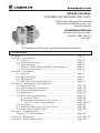
MODEL 224/224C
DIFFERENTIAL PRESSURE UNIT (DPU)
(M224C for Industrial Service and
Barton® brand M224 (non-C) for
Nuclear Service)
Installation Manual
(Replaces/Supersedes ID#10085)
Part No. 10087, Rev. 01
July 2007
[This manual is for DPU only - see separate instrument manual.]
CONTENTS
Prepages................................................................................ Section 1 - Introduction
1-1. General.................................................................... 1-2. Product Description................................................... 1-3. Specifications............................................................ Table 1-1. DPU Material/Range Specifications............. 1-4. Theory of Operation.................................................. Section 2 - Installation
2-1. General.................................................................... 2-2. DPU Mounting.......................................................... 2-3. DPU Piping............................................................... 2-4. DPU Piping/Startup Examples................................... Section 3 - Maintenance and Calibration
3-1. Required Tools.......................................................... 3-2. Test/Calibration Equipment........................................ 3-3. Preventative Maintenance........................................... 3-4. Calibration................................................................ 3-5. DPU Cleaning/Inspection........................................... A. Pressure Check..................................................... B. Cleaning and Inspection Procedure.......................... Table 3-1. Bolt Torque Ratings............................... 3-6. Servicing................................................................... 3-7. Attaching Drive Arm to Torque Tube........................... 3-8. Drive Arm Tightness Test........................................... Section 4 - Troubleshooting
Table 4-1. Troubleshooting................................................ Section 5 - Dimensions............................................................ Section 6 - Parts Drawing/List................................................. Page 2
Page 3
Page 3
Page 3
Page 4
Page 5
Page 7
Page 7
Page 7
Page 9
Page 19
Page 19
Page 19
Page 19
Page 19
Page 20
Page 20
Page 21/22
Page 23
Page 24
Page 24
Page 25
Page 26/27
Page 28
SAFETY
Before installing this instrument, become familiar with the installation instructions in
Section 2 and in the separate instrument manual.
DANGER notes indicate the presence of a hazard which will cause severe personal
injury, death, or substantial property damage if warning is ignored.
WARNING notes indicate the presence of a hazard which can cause severe personal
injury, death, or substantial property damage if warning is ignored.
CAUTION notes indicate the presence of a hazard which will or can cause moderate
personal injury or property damage if warning is ignored.
DANGER, WARNING, and/or CAUTION notes that appear on the following pages of
this manual should be reviewed before proceeding: 3, 7, 8, 19, 20, and 23. (Important!
Before installing or operating this instrument, review all safety notices contained in the
separate actuated instrument manual.)
PRODUCT WARRANTY STATEMENT
Product warranty for this instrument is as stated on the back cover of this manual.
NOTICE: DPU warranty will be voided if the following limitations are exceeded:
Temperature - Do not subject the DPU to temperatures above 200°F or below -60°F
(+40°F minimum for water filled units).
Pressure - Do not subject the DPU to operating pressures in excess of the working
pressure rating stamped on the unit or attached dataplate.
Corrosion - Do not subject the DPU to incompatible process media.
Sealed Components - Do not loosen or remove the torque tube gland nut, the drive arm
hole plug, or the torque tube housing from the centerplate. To do so will cause loss of
bellows fill fluid and render the unit inoperable.
Vibration/Shock - Do not subject the DPU to severe mechanical or hydraulic shock.
"C" VERSION DESIGN CHANGE
The 224C is a redesigned version of the 224 DPU. The "C" version is identical in function, performance, installation, and operation to the previous version - redesign was for
improved manufacturing only. This design change does not affect the instrument being
actuated. Barton-brand Model 224 (Non-C) DPU configurations are for
Nuclear service only.
RECORD OF CHANGES
VERSION
DATE
DESCRIPTION (initial issue 95E1 [5/95])
99D8
8/99
Updated specs., Table 4-1, Table 5-1, and Section 6 drawings
01D18d
4/01
Revised to Booklet Format
03G50c
7/03
Rev. Co. Name/Logo; Rev. Sections 1, 2, & 3 for PED compliance
03H50b
(ID#10087)
8/03
Rev. Spec. Table 1-1; Combined 224 and 224C (replaces 10080); Add
224 DPU information to Section 6
04C50b
(ID#10085)
8/03
Produced separate manual under Barton brand for Nuclear/Government
Service (No Tech. Changes from ID#10085)
06C75m
(ID#10087)
4/06
Eliminated separate Barton-brand manual (ID#10085); Rev. Safety/ "C"
Ver. statements; Rev. Tables 1-1, 3-1, and 6-1; Added Piping/Startup
Examples (para. 2-4); Rev. housing bolt caution to warning (page 8); Rev.
Figure 6-1; non-technical changes throughout
06D76a
4/06
Removed Government Service designation; No Tech. Changes.
01
7/07
Revised corporate name/logo/contact information to reflect Cameron
ownership.
SECTION 1 - INTRODUCTION
1-1. General
The Model 224/224C Differential Pressure Unit (DPU) is a mechanical device
that measures differential pressure relative to a gas or liquid flowing through a
process system, or to the level of a liquid contained in a process vessel.
For process flow measurements, the DPU is connected across a primary device
(e.g., venturi, orifice plate, or flow tube) located in the process system.
For liquid level measurements, the DPU may be connected in a variety of ways
to measure the difference in pressure caused by variations in the level of the
liquid in the process vessel.
1-2. Product Description
The Model 224/224C DPU is a dual bellows assembly enclosed within pressure
housings. The dual bellows assembly consists of two opposing internally connected liquid-filled bellows, a center-block, range springs, overrange valves, and
a torque tube assembly.
The pressure housings are connected by pipe or tubing to the primary device
located in the system piping. Variations in differential pressure within the
pressure housings cause the bellows to expand or contract in a linear direction
towards the side having the lowest pressure.
The linear movement of the bellows is converted into angular rotation when
transmitted to the torque tube shaft by the drive arm and this mechanical motion
actuates the mechanism of the process monitoring instrument.
The process monitoring instrument that is connected to the torque tube assembly may be an indicator, a switch, a transmitter, a recorder, or other process
control device.
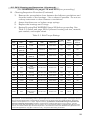
1-3. Specifications
The Model 224/224C DPU is available in various pressure ratings to measure
to specific ranges between 0-30 inches of water column and 0-1000 psi, with
safe working pressure (SWP) ratings from 500 to 10,000 psi (224 Non-C limited to 500 to 3,000 psi SWP). See Table 1-1, page 4.
The 224C Bellows Unit Assembly (BUA) is produced in three bellows sizes: 15/8 inch, 5/8 inch, and 3/4 inch diameter.
The 1-5/8 inch diameter BUA accommodates differential pressures to 55 psi.
The range springs of this BUA are contained within the bellows and do not
come in contact with the measured liquid.
The 3/4 inch BUA accommodates differential pressures up to 400 psi and the
5/8 inch BUA up to 1,000 psi. The range springs of these BUAs are grouped
around the outside of the bellows and must be of a material that is compatible
with the liquid being measured.
CAUTION
Ambient temperatures below +40°F should never be allowed for water
filled (D-fill) units.
Cold Rolled Steel (C1018)
Stainless Steel (316)
3,000
(207)
6,000
(414)
224C
1.55" (25.4 cc)
0.14" (2.3 cc)
1.55" (25.4 cc)
1.66" (27.2 cc)
0-100" w.c. (0-248 mbar) to
0-60 psi (0-4.1 bar)
0-60" w.c. (0-149 mbar) to
0-60 psi (0-4.1 bar)
0-30" w.c. (0-75 mbar) to
0-60 psi (0-4.1 bar)
1-5/8" (41mm) O.D.
0.03" (0.49 cc)
2.42" (39.7 cc)
2.51" (41.1 cc)
0-61 psi (0-4.2 bar) to
0-400 psi (0-27.6 bar)
0-61 psi (0-4.2 bar) to
0-400 psi (0-27.6 bar)
3/4" (19mm) O.D.
0.03" (0.49 cc)
2.42" (39.7 cc)
2.51" (41.1 cc)
0-61 psi (0-4.2 bar) to
0-400 psi (0-27.6 bar)
0-61 psi (0-4.2 bar) to
0-400 psi (0-27.6 bar)
0.025" (0.41 cc)
2.50" (40.9 cc)
2.61" (42.8 cc)
0-400 psi (0-27.6 bar) to
0-1000 psi (0-69 bar)
0-400 psi (0-27.6 bar) to
0-500 psi (0-34 bar)
0-400 psi (0-27.6 bar) to
0-500 psi (0-34 bar)
5/8" (16mm) O.D.
Inconel Bellows
3/4" (19mm) O.D.
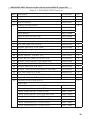
AVAILABLE DIFFERENTIAL PRESSURE RANGES
Beryllium Copper Bellows (224C Only)
1/4" NPT
9/16 AMINCO
(1/4" ODT)
1/2" NPT
1/2" NPT
1/4" NPT
MS-16142-4
1/4" NPT
1/4" NPT
Top
1/4" NPT
9/16 AMINCO
(1/4" ODT)
1/4" NPT
1/4" NPT
1/4" NPT
MS-16142-4
1/4" NPT
1/4" NPT
Bottom
PRESSURE CONNECTIONS
Notes: Zero center or split ranges available on special order (e.g., 0-60" w.c. (0-149 mbar) range may be ordered 30-0-30" w.c. (75-0-75 mbar) or (15-0-45" w.c. (37-0-112 mbar). Absolute pressure ranges available from 30" w.c. (75
mbar) to 600 psi (41.4 mbar). Other sizes and types of connections (welding stubs, MA, A.N.D., etc.) available upon request. Outline dimension drawings available upon request. Metric conversions ( ) are approximate. M224C with
NACE (MR-01-75) compliant materials available upon request. *Model 224 (Non-C) for specific Nuclear service applications only.
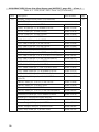
Performance: Torque Tube Rotation = 8° ±10%; Torque Tube Material = Beryllium Copper (BeCu); Temperature Limits = -40°F/°C to +180°F (+82°C); Maximum Non-linearity = per Range;
Repeatability = 0.2% of full scale differential pressure (see DP Indicators, Switches, & Transmitters bulletin #21920 for additional information).
0.14" (2.3 cc)
1.66" (27.2 cc)
H.P. Head
0-100" w.c. (0-248 mbar) to
0-60 psi (0-4.1 bar)
0-60" w.c. (0-149 mbar) to
0-60 psi (0-4.1 bar)
0-30" w.c. (0-75 mbar) to
0-60 psi (0-4.1 bar)
1-5/8" (41mm) O.D.
Stainless Steel or
Inconel Bellows
L.P. Head
Displacement cu.in. (cu. cm) for full-scale Travel
Net Volume
cu.in. (cu. cm)
10,000
(689)
Cold Rolled Steel (C1018)
Stainless Steel (316)
Monel
Alloy Steel (4140)
Cold Rolled Steel (C1018)
Stainless Steel (316)
Copper Nickel (70-30)
(MIL-C-15726)
Cold Rolled Steel (C1018)
Stainless Steel (316)
Forged Brass
(ASTM-B124#2)
Housing Material
BODY
1,500
(103)
1,000
(69)
500
(34)
500
(34)
SWP psi (bar)
224 (Non-C)*
Table 1-1. 224/224C DPU Material/Range Specifications (4/06a)
224/224C DPU Specifications
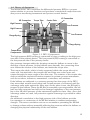
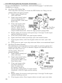
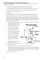
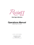
1-4. Theory of Operation
The M224/224C DPU measures the differential pressure (DP) in a process
system relative to process functions and produces a mechanical output that actuates process monitoring instruments and process control devices.
HP Connection
High Pressure
Torque Tube
Center Plate
LP Connection
Low Pressure
High Pressure
Range Spring
Low Pressure
Range Spring
Temperature
Compensator
Figure 1-1. DPU Components
The high-pressure (HP) housing is connected by pipe or tubing to the high-pressure side of the primary device. The low-pressure (LP) housing is connected to
the low-pressure side of the primary device.
Any pressure changes within the housings causes the bellows to move in the
direction of least pressure. As the bellows move laterally, the connecting drive
arm follows the motion of the bellows, and twists the torque tube.
The torque tube shaft, which is freely supported within the torque tube at its
outer end, but attached to the torque tube and drive arm at the inner end,
rotates through the same angle as the drive arm. The rotation of the torque tube
shaft provides the mechanical motion required to actuate process instruments,
such as recorders, indicators, transmitters, controllers, and switches.
If the bellows are subjected to a pressure greater than the range of the DPU,
they move their normal travel range and a small amount of overtravel until the
overrange valve seals against the valve seat. As the valve closes, the fill liquid is
trapped in the bellows. Since the fill fluid is essentially noncompressible, the bellows are fully supported and will not be damaged regardless of the overpressure
(up to the full rated pressure of the instrument) applied to them. Also, since dual
overrange valves are used, full protection against overrange is provided in either
direction.
An additional convolution in the high-pressure side of the bellows provides
for expansion or contraction of the fill fluid relative to ambient temperature
changes. This extra convolution acts as an accumulator permitting the fill fluid
to change volume without materially affecting the pressure within the bellows or
changing the physical relationship of the two bellows.
(Blank Page)
SECTION 2 - INSTALLATION
2-1. General
The instrument should be inspected at time of unpacking to detect any damage
that may have occurred during shipment. Note: The DPU was checked for
accuracy at the factory — do not change any of the settings during examination or accuracy will be affected.
For applications requiring special cleaning/precautions, a polyethylene
bag is used to protect the instrument from contamination. This bag
should be removed only under conditions of extreme cleanliness.
2-2. DPU Mounting
A. Flush or Panel
1. Cut an opening in the panel and drill four holes (17/64"), per outline
dimension drawings in Section 5.
2. Pass the instrument through the cutout in the panel (from panel front).
3. Attach the indicator to the panel with four screws.
C. Pipe
Refer to Section 5. The unit must be mounted approximately level for
proper operation.
2-3. DPU Piping
WARNING
HIGH PRESSURE HAZARD. TO PREVENT PERSONAL INJURY
OR DAMAGE TO EQUIPMENT, DIRECT ALL PIPING AWAY
FROM THE OPERATOR WHILE CONNECTING THE DPU TO
THE SYSTEM PIPING.
WARNING
EXPLOSION HAZARD. NO ORGANIC COMPOUNDS, OIL,
GREASE, DIRT, OR SCALE OF ANY KIND CAN BE TOLERATED
IN AN OXYGEN INSTALLATION.
WARNING
FOR INSTALLATIONS WHERE THE PRESSURE COULD EXCEED
THE RATED MAXIMUM SAFE WORKING PRESSURE OF THE
DPU, THE PIPING SYSTEM MUST INCLUDE PROTECTIVE
MEASURES TO PREVENT OVER PRESSURE, IN ACCORDANCE
WITH APPLICABLE LOCAL AND NATIONAL PIPING CODES.
WARNING
THE MODEL 224/224C DPU IS NOT DESIGNED FOR HIGH
STATIC OR DYNAMIC LOADS AT IMPULSE LINE CONNECTIONS.
THE IMPULSE PIPING SYSTEM MUST BE DESIGNED WITH
ADEQUATE SUPPORTS TO MINIMIZE THE LOADS AT THE
DPU.
2-3. DPU Piping (Cont.)
WARNING
DO NOT REUSE HOUSING BOLTS. SEE HOUSING BOLT
WARNING ON PAGE 20.
CAUTION
DPU pressure rating has been determined using standard methods
without specific considerations for corrosion (internal or external) or
fatigue. The system designer should appropriately derate any DPU
where these considerations are significant issues. Do not subject DPU
to unnecessary shock/overrange pressure during operation.
CAUTION
DPU bellows protects torque tube from exposure to process fluid.
Cyclic conditions can cause undetected bellows failure resulting in
exposure of the torque tube to the process fluid.
NOTICE
Do not share filling or vapor return lines with DPU piping lines.
Standard Piping Practices (observe when installing piping):
1. Shorten distance between primary device and DPU as much as possible. Distances exceeding 100 feet are not recommended. For distances up to
50 feet, use 1/4-inch pipe or tubing. For runs 50 to 100 feet, use 1/2inch pipe or tubing. The recommended limitation does not apply if an air
purge or blow-back system is used.
2. Slope all piping at least 1-inch/linear foot to avoid liquid/gas entrapment.
3. Provide two feet of un-insulated piping between the DPU and the primary
device for each 100 degrees in excess of +180°F (+162°C), if process
media exceeding +200°F (+93.3°C) must be measured.
4 Assure that the temperature of the DPU never exceeds 180°F (+162°C).
When steam tracing is necessary, the steam pressure should not exceed five
pounds per square inch and insulation should not be used. If pressure must
exceed five pounds per square inch, limit the length of tubing around the
DPU to two turns and do not insulate.
5. When severe pulsation is present, install a suitable pulsation dampening
device upstream of the DPU; otherwise, accuracy will be affected.
6. Mount DPU on a solid support to minimize vibration. Tighten all points,
using a suitable compound; leaks in piping can cause measurement errors.
7. Rotate the housing as necessary to place the connection in the proper position. The DPU has connections in the pressure housings to accommodate
various pipe sizes (refer to Section 5).
8. Install a valve manifold connecting the DPU and the source of differential
pressure to facilitate operation and checking of the DPU.
9. Install all shutoff and bypass valves so they are easily accessible from front
of instrument. Locate block valves at the source of differential pressure.
10. For gas service, it is recommended that zero check be performed with both
block valves closed. If gas flow is pulsating, a standing wave effect may be
in the process line displacing the indicator (appearing to be a zero error).
2-4. DPU Piping/Startup Examples
"Typical" piping diagrams and startup procedures are presented on pages 9-17.
For specific application/installation/piping information, contact Cameron.
Review all WARNINGS, CAUTIONS, AND NOTICES (pages 7 and 8) before
installation or startup.
• Flow Applications (pages 9-13) (HP = High Pressure)
Ensure DPU HP housing is connected to the primary device upstream tap.
NOTICE: To prevent overheating DPU during blow-down, operator should
monitor temperature by placing his hands on pipe between DPU and the manifold pipe containing the vent valves.
• Liquid Level Applications (pages 13-16)
The process media may be used as a reference leg seal fluid when it is of
a type that will condense in the reference leg under all conditions. If the
process or process media characteristics are such that the above conditions
cannot be met, a special reference leg seal fluid will be required.
If special seal fluid media characteristics are such that the above conditions
cannot be met, a special reference leg seal fluid will be required. The special seal fluid must not be volatile and must not be miscible with the process
media. The difference in densities (special seal fluid vs process media) will
require compensation in calculating differential pressure range of the DPU.
• Liquid Specific Gravity Applications (page 17)
This method of piping is used for determining specific gravity changes in a
process media using differential pressure instruments.
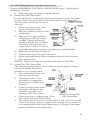
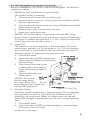
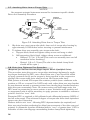
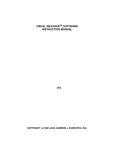
A. Gas Flow, DPU Above Run
Recommended for use whenever possible, as the DPU is self-draining.
However, NOT recommended when hydrates are present.
1. Open bypass valve(s) and close vent valve.
2. Open both shutoff valves
and one block valve to
pressurize DPU, then close
block valve.
3. Close one bypass valve and
check system for leaks.
If output travels upscale,
check for low-pressure
piping leaks. If output.
travels downscale, check for
high-pressure piping leaks.
Figure 2-1. Gas Flow,
4. Repair piping if necessary and repeat steps
DPU Above Run
1 through 3 until output remains stationary
at zero.
5. Close both shutoff valves and open bypass valve(s).
6. Open both block valves and slowly open both shutoff valves.
7. Close bypass valves and if two bypass valves are used, open vent valve.
8. Close bypass valves, and if two bypass valves are used, open vent
valve.
2-4. DPU Piping/Startup Examples (Continued)
Review all WARNINGS, CAUTIONS, AND NOTICES (pages 7 and 8) before
installation or startup.
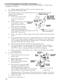
B. Gas Flow, DPU Below Run
Used only when necessary to mount the DPU below run. Drip pots are
required when wet gas is present.
1. Open bypass valve(s) and
close vent valve.
2. Open both shutoff valves
and one block valve to
pressurize DPU, then close
block valve.
3. Close one bypass valve
and check system for
leaks. If output travels
Figure 2-2. Gas Flow,
upscale, check for lowDPU Below Run
pressure piping leaks. If
output travels downscale, check for high-pressure piping leaks.
4. Repair piping if necessary and repeat steps 1 through 3 until output
remains stationary at zero.
5. Close both shutoff valves and open bypass valve(s).
6. Open both block valves and slowly open both shutoff valves.
7. Close bypass valves, and if two bypass valves are used, open vent
valve.
8. If drip pots are used, open drip valves and blow out accumulated liquid.
C. Gas Flow, Hydrates Present
The following is used if hydrates or heavy solids are present, piping and
shutoff not less than 1/2-inch in diameter. Bypass the manifold above to
isolate the meter from connecting piping. Drip pots
prevent plugging.
1. Open bypass valve(s) and
close vent valve.
2. Open both shutoff valves
and one block valve to
pressurize the DPU, then
close block valve.
3. Close one bypass valve
and check system for
leaks. If output travFigure 2-3. Gas Flow,
els upscale, check for
Hydrates Present
low-pressure piping leaks. If output travels
downscale, check for high-pressure piping
leaks.
4. Repair piping if necessary and repeat steps 1 through 3 until output
remains stationary at zero.
5. Close bypass valves. If two bypass valves are used, open vent valve.
10
2-4. DPU Piping/Startup Examples (Continued)
Review all WARNINGS, CAUTIONS, AND NOTICES (pages 7 and 8) before
installation or startup.
6. Drain drip pots of hydrates at regular intervals.
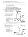
D. Steam Flow, DPU Below Run
For this application, condensing reservoirs and piping to orifice taps must
be level. Assure that the reservoir and steam lines are at the same level.
Two-inch pipe crosses may be used as
seal pots.
1. Close vent valves if used, open
bypass and shutoff valves.
2. Remove condensing reservoir side
and fill plugs.
3. Pour water into both reservoirs
until piping and DPU housings
are filled. Piping and housing
chambers shall be free of bubbles.
The pointer will rest at zero (or
output will be 4 mA or 10 mA as
applicable) when the instrument and piping are completely filled.
4. Install side and fill plugs in reservoirs.
5. Close shutoff valves and open block valves.
6. Slowly open both shutoff valves simultaneously and check for leaks.
7. Close bypass valve.
NOTICE: Ensure that plugs are used and never valves on the DPU.
E. Liquid Flow, DPU Above Run
The following steps should be used if sediments may be present. Inspect
piping periodically. Not recommended for hot or gassy liquids.
1. Close both shutoff valves and
open both block valves.
2. Open bypass valve. Crack
vent valves or loosen plugs
from top ports of DPU body
housings.
3. Crack and close shutoff valves
alternately until liquid is free
of bubbles and spills out of
both upper DPU body ports.
Figure 2-5. Steam Flow,
4. Close vent valves or tighten plugs. Close
DPU Above Run
block valves and open shutoff valves.
5. The pointer will rest at zero (or output will be 4 mA or 10 mA as applicable). If not and no leaks are detected, the housing and/or piping are
not completely filled with liquid. Repeat steps 1 through 4 until output
remains stationary at the lowest value.
11
2-4. DPU Piping/Startup Examples (Continued)
Review all WARNINGS, CAUTIONS, AND NOTICES (pages 7 and 8) before
installation or startup.
6. Slowly open both block valves and close bypass valve.
F. Liquid Flow, DPU Below Run
The following steps are recommended for hot or gassy liquids. Periodic
inspections of piping are
recommended.
1. Close both shutoff valves
and open both block
valves.
2. Open bypass valve. Crack
vent valves or loosen
plugs from top ports of
DPU pressure housings.
3. Crack and close shutoff
valves alternately until the
Figure 2-6. Liq.Flow,
liquid is free of bubbles and spills out of both
DPU Below Run
upper DPU body ports.
4. Close vent valves or tighten plugs. Close block valves and open shutoff
valves.
5. The pointer will rest at zero (or output will be 4 mA or 10 mA as applicable). If not and no leaks are detected, the housing and/or piping are
not completely filled with liquid. Repeat steps 1 through 4 until output
remains stationary at the lowest value.
6. Slowly open both block valves and close bypass valve.
7. For service with hot or gassy liquids, fill both sides of the manifold
through the fill tee, with the liquid to be measured cooled to +200°F
(+93.3°C) or less, expel gas bubbles from DPU and piping.
8. Open vent valve in the bypass valve. Tighten the fill plug when bubble
free liquid flows.
G. Corrosive Liquid Flow
1. Close shutoff valves and open
block valves.
2. Open bypass valve and close
DPU drain plugs.
3. Remove fill and side plugs
from seal pots.
4. Fill seal pots, piping and DPU
housing with immiscible seal
fluid by pouring into upper fill
Figure 2-7. Corrosive
ports. DPU housing tubing, and scale pots
Liquid Flow
must be filled to seal pot side ports with
bubble-free liquid. The pointer will indicate zero (or 4 mA or 10 mA as
applicable) when high and low pressure chambers are filled with liquid.
5. Install side plugs.
(continued on next page...)
12
2-4. DPU Piping/Startup Examples (Continued)
Review all WARNINGS, CAUTIONS, AND NOTICES (pages 7 and 8) before
installation or startup.
G. Corrosive Liquid Flow (Continued)
6. Slowly open each shutoff valve alternately, until bubble-free line liquid
spills from both upper fill plugs.
7. Replace fill plugs.
8. Open and close block valves. Check for piping leaks (repair as needed).
9. Close shutoff valves and open block valves.
10. Slowly open both shutoff valves and close bypass valve.
H. Cool Non-Condensing Liquid, DPU Level with Tank Bottom
High-pressure side of DPU is connected to bottom outlet of tank. The lowpressure side is connected to top or gas outlet of tank.
NOTICE: Do not share filling
or vapor return lines with DPU
Figure 2-8. Cool.
piping.
Non-Condensing Liq.
The following steps are suitable
for piping layout for water, oil, or
other media that will not condense in low-pressure piping.
1 . Close both shutoff valves,
open lower block valve and
crack vent valve.
2. Slowly open lower shutoff
valve. When bubble-free
liquid spills from vent, close
vent valve.
3. Open upper block valve and
slowly open shutoff valve.
4. Crack drain valve to remove any condensation and close drain valve.
I. Cool Non-Condensing Liquid, DPU Below Tank
High-pressure side of DPU is connected to the bottom outlet of tank. The
low-pressure side is connected to top or gas outlet of tank. The following
steps are suitable for piping
Figure 2-9. Cool.
layout for water, oil, or other
Non-Condensing Liq.
media that will not condense in
(DPU Below Tank)
low-pressure piping.
1 . Close both shutoff valves,
open lower block valve and
crack vent valve.
2. Slowly open lower shutoff
valve. When bubble-free
liquid spills from vent,
close vent valve.
(continued on next page...)
13
2-4. DPU Piping/Startup Examples (Continued)
Review all WARNINGS, CAUTIONS, AND NOTICES (pages 7 and 8) before
installation or startup.
I.
Cool Non-Condensing Liquid, DPU Below Tank (Continued)
3. Open upper block valve and slowly open shutoff valve.
4. Crack drain valve to remove any condensation and close drain valve.
NOTICE: Do not share filling or vapor return lines with DPU piping.
J. DPU Below Tank with Reference Leg
Cool Liquids:
Use of reference leg cancels out the "dead leg" (piping from the tank
bottom to center line of meter body). Seal fluid in reference leg must not
volatilize. Process media can be used as a reference leg seal fluid if it is
such that it will condense in reference leg under all conditions. Otherwise,
special, immiscible seal fluid must be used. Difference in densities between
process media and seal fluid must be considered when computing differential pressure range of DPU.
1. Partially fill reference leg by opening bottom block valve, both shutoff
valves, and bypass valve.
2. Crack drain plugs on the
DPU housing and vent the
valve. Close when clear,
bubble-free liquid flows.
3. Close bypass and shutoff
valve on reference leg.
4. Remove plug from the top
port in 2-inch pipe cross
connection, and fill the
reference leg manually.
5. Open top shutoff valve
and crack vent valve until
bubbles are expelled.
Leave the reference leg
full.
6. Replace plug in pipe cross
and close vent valve.
Figure 2-10. DPU Below
7. Slowly open upper block valve.
Tank w/Ref. Leg
Hot Liquids (Volatile):
1. Open both shutoff valves, bypass valve and vent valve.
2. Remove plug from the top port in 2-inch pipe cross. Fill both high and
low DPU housings with liquid until it runs out of vent valve. Use liquid
to be measured, cooled below +200°F (+93.3°C) or other suitable seal
liquid. Expel bubbles in DPU housing.
(continued on next page...)
14
2-4. DPU Piping/Startup Examples (Continued)
Review all WARNINGS, CAUTIONS, AND NOTICES (pages 7 and 8) before
installation or startup.
J. DPU Below Tank with Reference Leg (Continued)
Hot Liquids (Volatile): (Continued)
3. Close bypass and shutoff valve on reference leg.
4. Remove plug from top port in 2-inch pipe cross connection, and fill
reference leg manually.
5. Open top shutoff valve and crack vent valve until bubbles are expelled.
Leave reference leg full.
6. Replace plug in pipe cross and close vent valve.
7. Slowly open upper block valve.
NOTICE: Do not share filling or vapor return lines with DPU piping.
If bypass valve is opened at any time, the reference leg must be filled again.
If no bypass is installed, disregard steps 1, 2, and 3. Open the lower block
valve in step 6 and shut off valve in step 7.
K. Liquid CO2
The instrument may be located above or below the vessel. The recommended vapor generator is a 12-inch length of 1 to 1-1/2-inch diameter
pipe. Avoid traps or pockets between the vapor generator and the tank.
Install the inverted "U" shaped gas trap inside the vessel.
1. Close shutoff valves.
2. Open drain valve and DPU housing drain
plugs to remove all liquid from the system,
and close drains.
3. Open bottom block valve slowly
to allow liquid to enter gas generator. Assure that vent valve is
closed.
4. Open top block valve and
shutoff valves.
NOTICE: Do not insulate the piping below
the lower block valve.
Do not
share filling and vapor return lines
with the DPU piping lines.
Figure 2-11. Liq. CO2
L. Cryogenic Liquids
Instrument may be located above or below the vessel. The recommended
vapor generator is a spiral of 3/8-inch tubing. Install the inverted "U"
shaped gas trap inside vessel. Meters for oxygen service are specially
cleaned and packaged in polyethylene bags, and must be kept extremely
clean.
1. Close shutoff valves.
2. Open drain valve and DPU housing drain plugs to remove all liquid
from system, and close drains.
(continued on next page...)
15
2-4. DPU Piping/Startup Examples (Continued)
Review all WARNINGS, CAUTIONS, AND NOTICES (pages 7 and 8) before
installation or startup.
L. Cryogenic Liquids (Continued)
3. Open bottom block
valve slowly to
allow liquid to enter
gas generator.
Assure that vent
valves are closed.
4. Open top block
valve and open
shutoff valves.
NOTICE: Do not share filling or vapor return
lines with DPU piping.
Figure 2-12. Cryo Liq.
M. Bubbler System
Recommended when piping connections must be made at the top of the
tank or whenever solids or sludge are present.
1 . Set bubbler input gas regulator pressure slightly higher than process
vessel pressure.
2. Open block valves and
shutoff valves, and close
bypass valve.
3. Check sight-flow into bubbler tube.
4. Adjust bubbler system to
minimum flow by adjusting input gas regulator.
NOTICE: Do not share filling or vapor return lines with DPU piping.
16
2-4. DPU Piping/Startup Examples (Continued)
Review all WARNINGS, CAUTIONS, AND NOTICES (pages 7 and 8) before
installation or startup.
N. Liquid Specific Gravity
This method is for determining specific gravity changes in a process media
using a differential pressure instrument.
1 . Set bubbler input gas regulator pressure slightly higher than process
vessel pressure.
2. Open block valves and
shutoff valves, and close
bypass valve.
3. Check sight-flow into bubbler tube.
4. Adjust bubbler system
to minimum flow by
adjusting digit flow gages
throttling valves.
Figure 2-14. Liq. Specifc Gravity
17
(Blank Page)
18
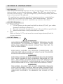
SECTION 3 - MAINTENANCE
3-1. Required Tools
Tool
Screwdriver
50 lb. Torque wrench
Purpose
Bracket Screws
Pressure housing bolts
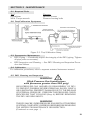
3-2. Test/Calibration Equipment
Figure 3-1. Test/Calibration Setup
3-3. Preventative Maintenance
•
DPU Piping — Periodically inspect the integrity of the DPU piping. Tighten
all pipe joints as necessary.
• DPU Inspection and Cleaning — See DPU Cleaning and Inspection Procedure that follows.
3-4. Calibration
For calibration procedures, refer to separate actuated instrument manual.
3-5. DPU Cleaning and Inspection
WARNING
(High Pressure Gas Installations
with pressures greater than 200 psig)
HIGH PRESSURE GAS HAZARD ON DISASSEMBLY OF DPU.
TO PREVENT POSSIBLE SEVERE PERSONAL INJURY, DEATH, OR SUBSTANTIAL PROPERTY DAMAGE DUE TO THE RELEASE
OF INTERNAL PRESSURE, PERFORM THE PRESSURE CHECK
PROCEDURE THAT FOLLOWS (Step A) BEFORE REMOVING
THE DPU HOUSING BOLTS.
WARNING
THE DPU MAY BE UNDER PRESSURE. ENSURE THAT THE PIPING
SYSTEM IS COMPLETELY DEPRESSURIZED BEFORE REMOVING
THE METER FOR MAINTENANCE OR INSPECTION.
(Continued on next page...)
19
3-5. DPU Cleaning and Inspection (Continued)
(See WARNINGS on page 19 before proceeding.)
WARNING.
(Housing Bolts)
DO NOT REUSE HOUSING BOLTS. IF BOLTS ARE DISTURBED,
REPLACE WITH NEW BOLTS, PER TABLE 3-1.
REUSE OF HOUSING BOLTS, ESPECIALLY IN CRITICAL.
APPLICATIONS LIKE HYDROGEN SULFIDE AND SALT WATER
EXPOSURES, CAN RESULT IN SEVERE INJURY, DEATH OR
SUBSTANTIAL PROPERTY DAMAGE DUE TO BOLT FAILURE.
NOTICE
If accumulation of solids or semi-solids is extensive, remove the
housings carefully to prevent damage to the bellows.
A. Pressure Check
WARNING
FAILURE TO PERFORM THIS PROCEDURE CAN RESULT IN
SEVERE INJURY, DEATH OR SUBSTANTIAL PROPERTY.
DAMAGE DUE TO THE RELEASE OF INTERNAL PRESSURE.
This procedure should be performed prior to removing the DPU housing
bolts, especially if the DPU has been installed in gas applications with working pressures greater than 200 psig.
1. Back off all housing bolts 4 turns.
2. Check for internal pressure by attempting to move the housing in and
out along the bolts.
a. If the housing moves freely — no pressure is present — servicing
or repair may continue.
b. If the housing does not move freely — the bellows may be pressurized and is POTENTIALLY HAZARDOUS if further disassembled.
Tighten the bolts and return the unit to the factory or authorized
service center for repair.
Tag the unit and specify “Gas in Bellows”.
B. Cleaning/Inspection Procedure
Instruments used in services where solids or semi-solids may accumulate
inside the pressure housings require periodic inspection and cleaning, as
follows.
1. Remove the DPU from service and remove the pressure housings.
2. Carefully remove the pressure housings from the bellows unit assembly.
NOTICE
If the accumulation of material inside the housing is extensive, rapid
removal of the housing may damage the bellows convolutions.
20
3-5. DPU Cleaning and Inspection (Continued)
(See WARNINGS on pages 19 and 20 before proceeding.)
B. Cleaning/Inspection Procedure (Continued)
3. Remove the accumulation from between the bellows convolutions and
from the inside of the housings. Use a solvent if possible. Do not use
a sharp instrument to clean between convolutions.
4. Assure that there are no broken range springs.
5. Replace the housings and O-rings.
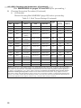
6. Review Housing Bolt WARNING (page 20) before proceeding. See
Table 3-1 (below and page 22) for pressure housing bolt size, material,
part number, and torque values.
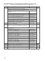
Table 3-1. Bolt Torque Ratings
HOUSING
BOLT
SWP
MATL.
MATL.
SIZE
PART NO.
LUBE
(Note 1)
TORQUE
LB-FT
(Note 2)
ROTATION
(Degrees)
(Note 3)
400
ALUM
(Note 6)
STEEL
1/4-28 x 2
0220-0035J
NO
8-10
135
400
ALUM
(Note 6)
18-8
1/4-28 x 2
0220-1016J
NO
8-10
135
500
BRASS
STEEL
1/4-28 x 2
0220-0035J
NO
8-10
135
500
BRASS
18-8
(Note 5)
1/4-28 x 2
0220-1010J
YES
10-12
450
500
BRASS
K-MONEL
1/4-28 x 2
0220-1018J
YES
8-10
180
500
STEEL
STEEL
1/4-28 x 2.5
0220-0029J
NO
12-14
180
500
SST
17-4 PH
1/4-28 x 2.5
0220-1017J
YES
12-14
180
500
SST
A286
(Salt Spray &
NACE)
1/4-28 x 2.5
0220-1112J
YES
16-18
—
500
SST
STEEL
(NACE)
1/4-28 X 1/2
S408-0067Z
NO
12
—
500
Cu-Ni
K-MONEL
1/4-28 x 2.5
0220-0045J
YES
9-11
180
1,000
Cu-Ni
K-MONEL
1/4-28 x 2.5
0220-0045J
YES
9-11
180
1,500
STEEL
STEEL
1/4-28 x 2.5
0220-0029J
NO
12-14
180
1,500
STEEL
K-MONEL
1/4-28 x 2.5
0220-0045J
YES
12-14
180
1,500
SST
STEEL
1/4-28 x 2.5
0220-0029J
NO
12-14
180
1,500
SST
17-4 PH
1/4-28 x 2.5
0220-1017J
YES
12-14
180
SST
A286
(Salt Spray &
NACE)
1/4-28 x 2.5
0220-1112J
YES
16-18
—
1,500
(table continued on next page . . .)
Notes: (1) Lubricant: Lightly apply Molykote G-n paste (0002-0010U) on the first two threads only, unless otherwise specified - do not lube bearing surface. Special applications such as Nuclear, Cryogenic, and oxygen services
may require special lubricants. Check BOM for specifics such as thread, head, and gasket surfaces. (2) Torque
on bolts is accomplished in 3 or 4 steps. Tighten uniformly. (3) Cameron recommends using a torque wrench
whenever installing housing bolts. Rotation of bolt head is measured after bolt is "snug" (approx. 1/16 turn
past head contact) with approximately 2 LB-FT torque. Do not exceed this rotation. To tighten bolts without torque
wrench, use rotation values. (4) Lube threads per Note 1 and under the head of the MP35N bolts. (5) Denotes for
commercial applications only. (6) For reference only - 400 psi ALUM housing is obsolete.
21
3-5. DPU Cleaning and Inspection (Continued)
(See WARNINGS on pages 19 and 20 before proceeding.)
B. Cleaning/Inspection Procedure (Continued)
6. (Continued)
Review Housing Bolt WARNING (page 20) before proceeding.
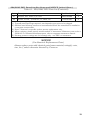
Table 3-1. Bolt Torque Ratings (Continued)
HOUSING
BOLT
LUBE
(Note 1)
TORQUE
LB-FT
(Note 2)
ROTATION
(Degrees)
(Note 3)
SWP
MATL.
MATL.
SIZE
PART NO.
3,000
STEEL
STEEL
3/8-24 x 2.5
0220-0022J
NO
30
90
3,000
SST
17-4 PH
3/8-24 x 1.5
0220-1028J
YES
40
90
3,000
SST
17-4 PH
3/8-24 x 3.0
0220-1015J
YES
35
90
3,000
SST
A286
(Salt Spray &
NACE)
3/8-24 x 2.5
0220-1111J
YES
34-36
—
3,000
SST
STEEL
(NACE)
3/8-24 x 2-1/2
S408-0065Z
NO
35
—
3,000
SST
17-4 PH
3/8-24 x 2.5
0220-1014J
YES
35
90
3,000
MONEL
17-4 PH
3/8-24 x 2.5
0220-1014J
YES
45
180
3,000
MONEL
A286
(Salt Spray &
NACE)
3/8-24 x2.5
0220-1111J
YES
19-21
—
6,000
STEEL
STEEL
3/8-24 x 2.5
0220-0022J
NO
35
135
6,000
SST
17-4 PH
3/8-24 x 2.5
0220-1014J
YES
40
135
6,000
SST
MP35N
(Salt Spray)
3/8-24 x 2.5
0220-1109J
(Note 4)
50-52
—
10,000
STEEL
STEEL
3/8-24 x 2.5
0220-0022J
YES
40
180
10,000
SST
17-4 PH
3/8-24 x 2.5
0220-1014J
YES
45
180
10,000
K-MONEL
17-4 PH
3/8-24 x 2.5
0220-1014J
YES
45
180
10,000
K-MONEL
STEEL
1/2-13 x 3.5
S408-0113C
NO
40
180
Notes: (1) Lubricant: Lightly apply Molykote G-n paste (0002-0010U) on the first two threads only, unless otherwise specified - do not lube bearing surface. Special applications such as Nuclear, Cryogenic, and oxygen services
may require special lubricants. Check BOM for specifics such as thread, head, and gasket surfaces. (2) Torque
on bolts is accomplished in 3 or 4 steps. Tighten uniformly. (3) Cameron recommends using a torque wrench
whenever installing housing bolts. Rotation of bolt head is measured after bolt is "snug" (approx. 1/16 turn
past head contact) with approximately 2 LB-FT torque. Do not exceed this rotation. To tighten bolts without torque
wrench, use rotation values. (4) Lube threads per Note 1 and under the head of the MP35N bolts. (5) Denotes for
commercial applications only. (6) For reference only - 400 psi ALUM housing is obsolete.
22
3-6. Servicing
Range Change
To change the range of the DPU, the bellows unit assembly (BUA) must be
replaced with a unit of the desired range.
BUA Replacement
WARNING
REVIEW ALL WARNINGS, CAUTIONS, AND NOTICES UNDER DPU
CLEANING AND INSPECTION (PAGES 19 AND 20) BEFORE PERFORMING
THIS PROCEDURE.
NOTICE
Do not loosen drive-arm hold plug (located on the top of the BUA center plate)
when removing the mounting bracket. If the plug is loosened, the fill fluid in the
bellows will be lost and the unit will be rendered inoperable.
1. Disconnect the DPU piping, remove the instrument from service, and
remove the mounting bracket from the DPU.
2. Loosen the actuated instrument drive arm and separate it from the torque
tube shaft. Do not disconnect the actuated instrument linkage.
NOTICE
See the actuated instrument's manual for particular components that
must be removed to gain access to the DPU mounting fasteners.
3. Perform Pressure Check Procedure (A) under DPU Cleaning and Inspection on page 20. If internal pressure was found, do not continue
this procedure.
4. Remove pressure housing bolts and pressure housings.
NOTICE
It is recommended that new O-Rings be used whenever pressure housings are replaced.
5. Install the pressure housings onto the new BUA and attach with
appropriate housing bolts (see Table 3-1 for torque requirements).
6. Re-attach DPU (See para. 3-7, page 24 for procedure) to the actuated
instrument.
NOTICE
(Drive Arm/Torque Tube Tightness Test)
For nuclear seismic/high impact qualified units, a tightness test must
be performed whenever a DPU is attached to an instrument. See para.
3-8., page 24 for specific instructions.
7. Install the assembled instrument into service (in reverse order of removal)
and calibrate, per separate actuated instrument manual.
23
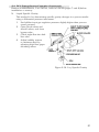
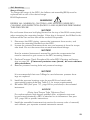
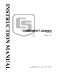
3-7. Attaching Drive Arm to Torque Tube
NOTICE
See separate actuated instrument manual for instrument specific details.
Drive Arm Assembly Procedure
SINTERED
CLAMP BLO CK
LINK
.03 (approx)
DRIVE
ARM
M224/M224C
LINK
DRIVE
ARM
SLO TTED
CLAMP BLO CK
3/32" ALLEN
W RENCH
CLAMP
SCREW
1/8" W RENCH 0163-0044C
SHAFT
TO TIGHTEN
SHAFT
CLAMP
SCREW
TO TIGHTEN
Figure 3-2. Attaching Drive Arm to Torque Tube
1. Slip drive arm over torque tube shaft; clear end of torque-tube housing by
approximately 0.030-inches before securing to prevent interference.
2. To tighten drive arm assembly onto torque-tube shaft:
a. Support block/shaft and tighten clamp screw until snug to shaft.
b. Still supporting block/shaft, tighten clamp screw an additional:
• Sintered: 1/3 to 1/2 turn (This screw can normally turn one full
revolution before breaking.)
• Slotted: 1/4 to 1/3 turn (The slot in the slotted clamp block
should still be open.)
3-8. Drive Arm Tightness Test Procedure
(Required for Nuclear Seismic/High Impact Shock Qualified Units)
This procedure tests drive arm to torque-tube attachment tightness by applying torque developed by DPU onto a fixed drive arm. Care should be taken
to apply pressure slowly as the torque is being applied to the connection
through the torque-tube drive shaft and not the torque-tube itself.
With pointer at normal 0% torque-tube rotation position (max. minimum scale
position or 0% on a normal 0 to 100% scale unit), adjust drive arm stop bracket
(or use alternate means) to prevent pointer from moving (stop bracket interferes
with drive arm movement). Note: On reverse acting and split range units, the
DPU must be pressurized to move pointer to max. minimum scale position and
on suppressed units it will be necessary to apply pressure to establish a reference
point to check for “zero” shift.
Pressurize DPU as required to full calibrated scale differential pressure (100% of
the full scale range). This achieves 8-degree of torque-tube drive shaft equivalent
torque onto the connection.
Observe shift in unit “zero” following DPU depressurization (as required) and
drive arm stop bracket readjusting (to allow free movement of the drive arm and
pointer). A downscale (counter-clockwise) shift in “zero” of greater than 1/2% is
indicative of drive arm slippage necessitating further clamp block tightening.
24
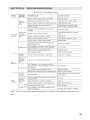
SECTION 4 - TROUBLESHOOTING
Table 4-1. Troubleshooting
Note: See actuated instrument manual for additional troubleshooting information.
25
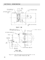
SECTION 5 - DIMENSIONS
Figure 5-1. 224/224C Dimensional Drawing (Part 1 of 2)
(based on 224C-12303, Rev. 00)
26
27
Figure 5-1. 224/224C Dimensional Drawing (Continued) (Part 2 of 2)
(based on 224C-12303, Rev. 00)
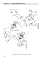
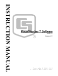
SECTION 6 - PARTS DRAWING/LIST
Figure 6-1. 224/224C DPU Parts Drawing
28
224/224C DPU Parts List (See Notes and NOTICE, page 33)
Table 6-1. 224/224C DPU Parts List
Item
Description
Part Number
1
Bellows Unit Assembly, 3/4" or 5/8"
Specify
2
Bellows Unit Assembly, 1-5/8"
Specify
-
3
Spacer, Bracket
0224-0302C
1
4
O-Ring, Housing Gasket
Qty.
-
2
Buna-N
0001-0028R
Viton
0001-0039R
Viton (NACE)
0001-1164R
Viton (10,000 psi units only)
0001-0062R
EPT
0001-1054R
5
Bracket, Mounting (Not for use with Brass Housings)
0273-0001C
2
6
Nut, Hex, Steel, 5/16-18 CP
0500-0033J
4
7
Washer, Split Lock, 5/16" Steel
0003-0006K
4
8
2" Pipe Mounting Kit (w/U-bolts, Nuts, & Washer)
0440-0001J
2
9
Not Used
10
Screw, Hex Hd., 1/4-28 x 1/2"
0116-1011J
8
11
Screw, Rd. Hd., Steel CP, 10-32 x 3/8"
0111-0057J
4
12
Bracket, Flush (500 psi Forged Brass only)
0224-0235B
1
13
Screw, Fil. Hd., SST, 10-32 x 1/2"
0114-0031J
4
14
Washer, Split Lock, #10, SST
0003-0032K
4
15
Bracket, Universal Mounting (Wall or Yoke Mtg.)
0273-0003C
1
16
Nut, Hex, Steel CP, 1/4-28
0500-0011J
4
17
Washer, Lock, Ext. Tooth, SST, 1/4"
0003-0068K
12
18
Screw, Fl. Hd., Steel CP, 1/4-28 x 1/2"
0112-0018J
4
19
Housing, Pressure (See Note 5)
2
224C DPU
Brass, Forged, 500 psi, 1/4 NPT Ports
224C-1016C
Brass, Forged 500 psi, 1/8 NPT Ports
224C-1018C
Steel, 500/1500 psi, 1/4 NPT Ports
224C-1113C
Steel, 500/1500 psi, 1/4 X 1/2 NPT Ports
224C-1123C
Steel, 500/1500 psi, 1/2 NPT Ports
224C-1130C
Steel, 3000/6000 psi, 1/2 X 1/4 NPT Ports
224C-1108C
Steel, 3000/6000 psi, 1/4 NPT Ports
224C-1120C
Steel, 3000/6000 psi, 1/2 NPT Ports
224C-1128C
29
224/224C DPU Parts List (See Notes and NOTICE, page 33)
(Cont.)
Table 6-1. 224/224C DPU Parts List (Continued)
Item
19
Description
Part Number
Housing, Pressure (See Note 5) (Continued)
2
224C DPU (Continued)
Steel, 10,000 psi, 1/4 NPT Ports
224C-1049C
Steel, 10,000 psi, 9/16 AMINCO Ports
224C-1189C
Cu-Ni, 1000 psi, 1/4 NPT Ports
224C-1021C
Cu-Ni, 1000 psi, 1/2 NPT Ports
224C-1022C
Cu-Ni, 1000 psi, 1/8 NPT Ports
224C-1292C
SST, 500/1500 psi, 1/2 NPT Ports
224C-1032C
SST, 500/1500 psi, 1/4 NPT Ports
224C-1033C
SST, 500/1500 psi, 3/8 NPT Ports
224C-1036C
SST, 500/1500 psi, 1/8 NPT Ports
224C-1238C
SST, 500/1500 psi, 1/4 NPT Ports (NACE)
0224-1621C
SST, 500/1500 psi, 1/4 X 1/2 NPT Ports (NACE)
0224-1626C
SST, 500/1500 psi, 1/2 NPT Ports (NACE)
0224-1697C
SST, 3000/6000 psi, 1/4 NPT Ports
224C-1040C
SST, 3000/6000 psi, 1/2 NPT Ports
224C-1041C
SST, 3000/6000 psi, 1/4 X 1/2 NPT Ports
224C-1042C
SST, 3000/6000 psi, 9/16 AMINCO Ports
224C-1187C
SST, 3000/6000 psi, Seal Welded, 3/4
0224-1641C
SST, 3000/6000 psi, 1/4 X 1/2 NPT Ports
(NACE)
0224-1637C
Monel, 3000 psi, 1/4 X 1/2 NPT Ports
224C-1028C
Monel, 3000 psi, 1/2 NPT Ports
224C-1029C
Monel, 3000 psi, 1/4 NPT Ports
224C-1121C
Monel, 3000 psi, 1/4 X 1/2 NPT Ports (NACE)
0224-1685C
K-Monel, 10,000 psi, 9/16 AMINCO Ports
224C-1215C
224 (Non-C Version) DPU (See Note 3)
30
Qty.
Brass, Forged, 500 psi, Absolute (No Ports)
0224-1602C
Brass, Forged, 500 psi, 1/4 NPT Ports
0224-1532C
Brass, Forged, 500 psi, 1/8 NPT Ports
0224-1606C
Steel, 500/1500 psi, 1/4 NPT Ports
0224-1576C
224/224C DPU Parts List (See Notes and NOTICE, page 33) (Cont.)
Table 6-1. 224/224C DPU Parts List (Continued)
Item
19
Description
Part Number
Housing, Pressure (See Note 5) (Continued)
Qty.
2
224 (Non-C Version) DPU (See Note 3) (Continued)
Steel, 500/1500 psi, 1/2 NPT Ports
0224-1577C
Steel, 500/1500 psi, Absolute (No Ports)
0224-1664C
Steel, 500/1500 psi, 3/8 NPT Ports
0224-1667C
Steel, 500/1500 psi, 1/4 X 1/2 NPT Ports
0224-1613C
Steel, 3000/6000 psi, Absolute (No Ports)
0224-1715C
Steel, 3000/6000 psi, 1/4 NPT Ports
0224-1555C
Steel, 3000/6000 psi, 1/2 NPT Ports
0224-1578C
Steel, 3000/6000 psi, 1/4 X 1/2 NPT Ports
0224-1607C
Steel, 10,000 psi, 1/4 NPT Ports
0224-1662C
Steel, 10,000 psi, 9/16 AMINCO Ports
0224-1663C
SST, 500/1500 psi, 1/4 NPT Ports
0224-1543C
SST, 500/1500 psi, 1/2 NPT Ports
0224-1579C
SST, 500/1500 psi, 1/4 X 1/2 NPT Ports
0224-1610C
SST, 500/1500 psi, Absolute (No Ports)
0224-1618C
SST, 500/1500 psi, 1/4 NPT Ports, Nipple Mod.
0224-1619C
SST, 500/1500 psi, 1/8 NPT Ports
0224-1675C
SST, 500/1500 psi, Seal Welded, 1/2 NPT Ports
0224-1679C
SST, 500/1500 psi, 3/8 NPT Ports
0224-1721C
SST, 500/1500 psi, 1/2 NPT Ports (NACE)
0224-1697C
SST, 500/1500 psi, 1/4 NPT Ports (NACE)
0224-1621C
SST, 500/1500 psi, Seal Welded, 1/4 NPT Ports
0224-1622C
SST, 500/1500 psi, 1/4 X 1/2 NPT Ports (NACE)
0224-1626C
SST, 3000/6000 psi, 1/4 NPT Ports
0224-1556C
SST, 3000/6000 psi, 1/2 NPT Ports
0224-1580C
SST, 3000/6000 psi, 1/4 X 1/2 NPT Ports
0224-1608C
SST, 3000/6000 psi, Seal Welded, 3/4
0224-1641C
SST, 3000/6000 psi, 9/16 AMINCO Ports
0224-1645C
SST, 3000/6000 psi, 1/4 X 1/2 Ports, Nipple
Mod.
0224-1647C
31
224/224C DPU Parts List (See Notes and NOTICE, page 33) (Cont.)
Table 6-1. 224/224C DPU Parts List (Continued)
Item
19
Description
Part Number
Housing, Pressure (See Note 5) (Continued)
Qty.
2
224 (Non-C Version) DPU (See Note 3) (Continued)
SST, 3000/6000 psi, 1/4 X 1/2 NPT Ports
(NACE)
0224-1637C
Cu-Ni, 1000 psi, 1/4 NPT Ports
0224-1581C
Cu-Ni, 1000 psi, 1/4 X 1/2 NPT Ports
0224-1616C
Cu-Ni, 1000 psi, Absolute (No Ports)
0224-1651C
Cu-Ni, 1000 psi, 1/2 NPT Ports
0224-1655C
Monel, 3000 psi, 1/4 X 1/2 NPT Ports (NACE)
0224-1685C
Monel, 3000 psi, 1/4 X 1/2 NPT Ports
0224-1687C
Monel, 3000 psi, 1/2 NPT Ports
0224-1696C
20
Spacer, DPU Mounting
0224-1547C
1
21
Bolt, Housing
(Refer to Housing Bolt WARINING on page 20.)
Refer to Table
3-1, pg. 21/22
for Part No.
4
22
Plug, Pipe/Port
2
Pipe Plug, 1/4" NPT Brass
0224-0100C
Pipe Plug, 1/8" NPT, Brass
0224-0058C
Pipe Plug, 1/8" NPT, SST
0224-1676C
Pipe Plug, 1/4" NPT, Steel CP
0199-0191C
Pipe Plug, 1/4" NPT, Monel
0199-0235C
Pipe Plug, 1/4" NPT, SST
0199-0214C
Pipe Plug, 1/2" NPT, Steel CP
0199-0192C
Pipe Plug, 1/2" NPT, SST
0199-0215C
Pipe Plug, 1/2" NPT, Monel
0199-0234C
Pipe Plug, 3/8" NPT, SST
0605-0010L
23
Screw, 1/4-28 x 5/8", Steel, CP
0111-0033J
4
24
Washer, Lock, Ext. Tooth, SST, 1/4"
0003-0068K
4
25
Bracket, Mounting (Not for use with Brass Housings)
0224-0055C
2
26
Nut, Hex, 1/4-28, Steel, CP
0500-0011J
4
32
224/224C DPU Parts List (See Notes and NOTICE, below) (Cont.)
Table 6-1. 224/224C DPU Parts List (Continued)
Item
Description
Part Number
Qty.
27
Washer, Ext. Tooth, 1/4" SST
0003-0068K
4
28
Screw, Fl. Hd., 1/4-28 x 1/2", Steel, CP
0112-0018J
4
Notes:
(1) Typically two Pipe Plugs required, size depends upon ports to be plugged.
(2) Stainless steel housing screws are recommended when the instrument is installed in
a corrosive environment.
(3) Non-C Versions for specific nuclear service applications only.
(4) When ordering, please specify model number of instrument. Minimum parts order is
$100.00. For actuated instrument parts, refer to separate instrument manual.
(5) Housing pressure ratings are for housings only - not DPU or instrument.
NOTICE
(Use Identical Replacement Parts)
Always replace parts with identical parts (same material, rating(s), certs,
size, etc.), unless otherwise directed by Cameron.
33
(Blank Page)
34
Product Warranty
A. Warranty
Cameron International Corporation ("Cameron") warrants that at the time
of shipment, the products manufactured by Cameron and sold hereunder
will be free from defects in material and workmanship, and will conform to
the specifications furnished by or approved by Cameron.
B. Warranty Adjustment
(1) If any defect within this warranty appears, Buyer shall notify Cameron
immediately.
(2) Cameron agrees to repair or furnish a replacement for, but not install,
any product which within one (1) year from the date of shipment by
Cameron shall, upon test and examination by Cameron, prove defective within the above warranty.
(3) No product will be accepted for return or replacement without the
written authorization of Cameron. Upon such authorization, and in
accordance with instructions by Cameron, the product will be returned
shipping charges prepaid by Buyer. Replacements made under this
warranty will be shipped prepaid.
C. Exclusions from Warranty
(1) THE FOREGOING WARRANTY IS IN LIEU OF AND EXCLUDES ALL
OTHER EXPRESSED OR IMPLIED WARRANTIES OF MERCHANTABILITY, OR FITNESS FOR .
A PARTICULAR PURPOSE, OR OTHERWISE.
(2) Components manufactured by any supplier other than Cameron shall bear
only the warranty made by the manufacturer of that product, and Cameron
assumes no responsibility for the performance or reliability of the unit as a
whole.
(3) "In no event shall Cameron be liable for indirect, incidental, or consequential damages nor shall the liability of Cameron arising in connection with
any products sold hereunder (whether such liability arises from a claim
based on contract, warranty, tort, or otherwise) exceed the actual amount
paid by Buyer to Cameron for the products delivered hereunder."
(4) The warranty does not extend to any product manufactured by Cameron
which has been subjected to misuse, neglect, accident, improper installation
or to use in violation of instructions furnished by Cameron.
(5) The warranty does not extend to or apply to any unit which has been
repaired or altered at any place other than at Cameron's factory or service
locations by persons not expressly approved by Cameron.
Product Brand
Barton® is a registered trademark of Cameron International Corporation .
("Cameron").
35
MEASUREMENT SYSTEMS
Formerly: NuFlo Measurement Systems • Barton Instrument Systems • Caldon, Inc.
HOUSTON
HEAD OFFICE
ASIA
PACIFIC
281.582.9500
603.2287.1039
[email protected]
NORTH
AMERICA
EUROPE,
MIDDLE EAST
& AFRICA
1.800.654.3760
[email protected]
44.1243.826741
[email protected]
USA • CANADA • UK • SCOTLAND • CHINA • UAE
ALGERIA • MALAYSIA • SINGAPORE • www.c-a-m.com/flo