1
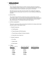
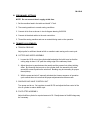
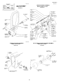
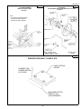
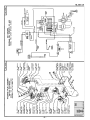
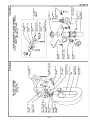
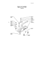
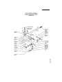
ML199-4
CLINTON'S
MODEL 199
UNDERBED TRIMMER
FOR
UNION SPECIAL 63900
PULLOFF
ASSEMBLY
NIPPER
NEEDLE
COOLER
TRIM AND WIPER
ASSEMBLY
FOLDER OPENER
SERVICE MANUAL
40-0252-01
ML199-5
TABLE OF CONTENTS
THREAD TRIMMER SECTION
SECTION
SECTION
I
II
GENERAL INFORMATION . . . . . . . . . . . . . . . . . . . . . .
1
A. INTRODUCTION . . . . . . . . . . . . . . . . . . . . . . . . . . .
B. APPLICATION . . . . . . . . . . . . . . . . . . . . . . . . . . . . .
C. TRIMMER COMPONENTS . . . . . . . . . . . . . . . . . . .
1
1
1
TRIMMER INSTALLATION . . . . . . . . . . . . . . . . . . . . . .
2
A.
B.
C.
D.
E.
F.
PULLOFF ASSEMBLY . . . . . . . . . . . . . . . . . . . . . . .
TENSION RELEASE AND PULLOFF ASSEMBLY. .
CUTTER AND WIPER ASSEMBLY . . . . . . . . . . . . .
SOLENOID AIR VALVE CONTROL UNIT. . . . . . . . .
NEEDLE COOLER . . . . . . . . . . . . . . . . . . . . . . . . .
FOLDER OPENER . . . . . . . . . . . . . . . . . . . . . . . . . .
2
2
2
2
2
2
SECTION
III
PRELIMINARY SETTINGS . . . . . . . . . . . . . . . . . . . . . . .
3
SECTION
IV
TRIMMER ADJUSTMENTS . . . . . . . . . . . . . . . . . . . . . .
3
A.
B.
C.
D.
E.
F.
TENSION RELEASE AND PULLOFF ASSEMBLY . .
CUTTER AND WIPER ASSEMBLY . . . . . . . . . . . . .
SOLENOID AIR VALVE CONTROL UNIT . . . . . . . .
FOOTLIFTER ASSEMBLY . . . . . . . . . . . . . . . . . . .
NEEDLE COOLER . . . . . . . . . . . . . . . . . . . . . . . . .
FOLDER THREAD WIPER . . . . . . . . . . . . . . . . . . .
3
3
3
3
4
4
TRIMMER SEQUENCE OF OPERATION . . . . . . . . . . .
4
A. UNDERBED TRIMMER . . . . . . . . . . . . . . . . . . . . . .
B. TENSION RELEASE . . . . . . . . . . . . . . . . . . . . . . . .
C. NEEDLE THREAD WIPER . . . . . . . . . . . . . . . . . . .
4
4
4
5
SECTION
V
SECTION
VI
TROUBLE SHOOTING . . . . . . . . . . . . . . . . . . . . . . . . .
SECTION
VII
PARTS DRAWINGS . . . . . . . . . . . . . . . . . . . . . . . . . . . . 6-12
ML199-6
I.
GENERAL INFORMATION
A. INTRODUCTION
The air Operated Underbed Trimmer contains a trimming system that cuts both the
needle and bobbin threads simultaneously. A movable and a stationary blade, mounted
on the throat plate are used in combination to pick up and cut the threads.
Solid state electronics are used to sense the position of the needle and to trigger the
trimming mechanism at the proper time as well as to control footlifting and backtacking
operations.
B. APPLICATION
The underbed Trimmer/Positioner enables the operator to automatically control the
position of the needle in or out of the work, thereby eliminating the need for hand positioning. In addition, the top and bottom threads are automatically cut beneath the throat
plate after positioning. This eliminates the need for hand trimming.
C. SYSTEM COMPONENTS
The trimmer components, which can be either pre-installed on the sewing machine head
and factory tested, or field installed, include:
1. Standard Components
a. Pulloff Assembly
b. Tension Release and Pulloff Assembly
c. Thread Cutter and Wiper Air Cylinder Assembly
d. Solenoid Air Valve Control Unit
2. Optional Components
e. Foot Lifter
f. Needle Cooler
g. Folder Opener
D. TUBING
1/8” O.D. X 1/16” I.D.
MATERIAL VINIL
30-1134-01 CLEAR
-02 YELLOW
-03 RED
-04 BLACK
-05 BLUE
-06 GREEN
-07 ORANGE
-08 WHITE
-09 GRAY
-10 BROWN
3/16” O.D. X 3/32” I.D.
MATERIAL POLYURETHANE
30-1540-01 CLEAR
-02 YELLOW
-03 RED
-04 BLACK
-05 BLUE
-06 GREEN
-07 ORANGE
-08 WHITE
-09 GRAY
-10 BROWN
1/4” O.D. X 1/8” I.D.
MATERIAL POLYURETHANE
30-2102-01 CLEAR
-03 RED
ML199-7
II.
TRIMMER INSTALLATION
A. PULLOFF ASSEMBLY
Remove the machine face plate and mount the Pulloff assembly as shown in INS-2377.
B. TENSION RELEASE AND PULLOFF ASSEMBLY
1. Remove from the machine the thread tension discs assembly and tension release
pin.
2. Drill and Tap mounting holes using appropriate drill fixture supplied. Refer to machine
drilling instructions shown in drawing INS-2355.
3. Mount tension release assembly and the thread tension discs assembly to the sewing
machine as shown in drawing INS-2353.
C. CUTTER AND WIPER ASSEMBLY
1. Remove from the machine throat plate and feed shaft clamp plate.
2. Rework clamp plate as shown in drawing INS-1630 and fasten to the machine.
3. Fasten cutter and wiper cylinder assembly to sewing machine bed.
4. Mount new throat plate assembly on the machine with original hook basket retaining
finger.
D. SOLENOID AIR VALVE CONTROL UNIT
1. Mount solenoid valve assembly in back of the machine bed as shown in INS-2379.
2. Mount foot lifter air cylinder assembly as shown in INS-2379.
E. NEEDLE COOLER
1. Fasten needle cooler tube to presser foot and roller housing bracket.
2. Mount treadle air valve assembly supplied between the motor and treadle arm.
F. FOLDER OPENER
1. Mount folder opener air cylinder assembly on bed of machine.
2. Assemble the folder opener assembly to the machine cylinder arm.
-2-
ML199-8
III. PRELIMINARY SETTINGS
NOTE: Do not connect the air supply at this time.
1. Set the machine head in the table and install "V" belt.
2. Time sewing machine to normal sewing conditions.
3. Connect all air lines as shown in circuit diagram drawing INS-2339.
4. Connect all electrical cables to the main control box.
5. Thread the sewing machine and sew on material being used on the operation.
IV. TRIMMER ADJUSTMENTS
A. TENSION RELEASE
Adjust puller for sufficient thread tail left on needle to start sewing on the next cycle.
B. CUTTER AND WIPER ASSEMBLY
1. Loosen the 10-32 nut on the cylinder shaft and adjust the knife travel so that the
cutting edge is about 1/16" past the cutting edge of the stationary blade.
2. Adjust the wiper to pass between the needle and the presser foot without striking
either. By loosening the two nuts on the cylinder shaft, the assembly will rotate
around the screw to position the wire hook. Bending may be necessary for proper
thread pickup.
3. With the power and air off, manually stimulate the trimmer sequence of operation
cycle several times to insure that the proper adjustments have been made.
C. SOLENOID AIR VALVE CONTROL UNIT
Turn power and air on. Set regulator to read 60 PSI and adjust the flow control of the
trim air cylinder to reduce bobbin spin.
D. FOOTLIFTER ASSEMBLY
Adjust footlifter cylinder for required amount of lift. Readjustment of footlift linkage may
be necessary.
-3-
ML199-9
E. NEEDLE COOLER
Adjust the flow control for the desired air flow to cool the needle and keep the throat plate
knife clean.
F. FOLDER OPENER
Adjust folder opener mounting bracket for required amount of opening.
V. TRIMMER SEQUENCE OF OPERATION
A. UNDERBED TRIMMER
The operation of the underbed trimmer is as follows:
1. Needle positioner stops with the needle thread positioned between the 5 and 6 o'clock
position across the hook. The needle is used for the reference point or 12 o'clock
position.
2. The movable knife is extended into the needle loop and in position to pick up the
bobbin thread.
3. The needle positioner moves the takeup and needle to up position.
4. The tension release, the pulloff and wiper cylinders operate after the positioner
reaches to up position.
5. Then the movable knife is returned to cut both needle and bobbin threads.
B. TENSION RELEASE
The needle thread tension is released so that the thread puller can pull off enough
thread to start the next sewing operation.
C. NEEDLE THREAD WIPER
The needle thread wiper pulls the needle thread above the foot before it is raised. If the
thread is trapped under the foot a long tail will be left at the start of the next sewing
opera-tion.
-4-
ML199-10
VI.TROUBLESHOOTING
PROBLEM
PROBABLE CAUSE
CORRECTIVE ACTION
Positioner solenoid binding
Remove bind
Movable blade missed needle
loop
Check synchronizer timing
to see that trimmer is fired
at correct time
Binds in trimmer linkage
Locate and remove bind.
A light bind would slow it
enough to miss needle
loop
Defective movable blade
Replace
Water in air lines
Check filter. Remove
water from air lines
Defective solenoid air valve or air
cylinder
Repair or replace
Defective needle positioner logic
Repair logic
Binds in trimmer linkage
Locate and remove bind
Defective movable or stationary
blade
Replace
Stroke misadjusted failing to
reach cutting position
Readjust
Needle thread cut short
Pulloff cylinder improperly
adjusted
Readjust
Long tail left on top side at
start of sewing
Wiper not operating or incorrectly
positioned causing thread to be
trapped under foot
Repair or reposition thread
wiper as required
Bobbin tension too tight
Lossen bobbin tension as
much as possible
Bobbin thread slipped out of hook
on case
Run bobbin thread
through hook
Bobbin case without hook being
used
Replace with correct
bobbin case
Needle thread not cut.
Bobbin thread is cut
Both threads not cut not
picked up
Both threads picked up not
cut
Bobbin thread is cut short
-5-
ML199-11
INS-2377C
INS-2337E
TRIM AND WIPER ASSEMBLY
PULLOFF ASSEMBLY
MODEL 199 FOR U.S. 63900
80-0514-01
MODEL 199 U.S. 63900
80-0503-01
INS-2354A
INS-2353C
TENSION RELEASE ASSEMBLY
AIR CYLINDER THREAD RELEASE ASSEMBLY
MODEL 199 U.S. 63900
80-0517-01
MODEL 199 U.S. 63900
10-1403-01
-6-
DRILLING INSTRUCTIONS / DRILL FIXTURE KIT
ML199-12
MODEL 199 FOR U.S. 63900
10-1405-01
INS-2355A
INS-765B
DRILLING AND MOUNTING INSTRUCTIONS
THREAD NIPPER ASSEMBLY 61400 M, T, W - 63900 M, T, W
REWORK - TAKEUP SPRING THREAD WIRE 61400 M, T, W
63900 M, T, W
THREAD NIPPER
01-4944-01
01-5010-01
BASE PLATE
SPRING
STEP 1.
REMOVE LOWER NEEDLE
THREAD EYELET & SCREW
AS SHOWN.
01-3053-01
STUD
01-3038-61
01-5798-01
BUSHING
BRACKET
01-3052-01
01-4943-01
NUT
PLATE NIPPER
STEP 2.
REPLACE EYELET & SCREW
WITH THREAD NIPPER
ASSEMBLY (10-0477-01).
.312
.656
10-0477-01
61400 M, T, W
THREAD NIPPER
.187
STEP 1.
DRILL AND TAP HOLE SQUARE (90O) TO SURFACE
OF MACHINE USING # 31 DRILL AND UNION
SPECIAL #V107 TAP.
UNION SPECIAL
# 61453-6
61400 M, T, W
STEP 2.
MOUNT THREAD NIPPER ASSEMBLY (10-0477-01).
CUT OFF SHADED AREA
-7-
ML199-13
INS-2335B
INS-1667C
ACCUSTOP
FOLDER ASSEMBLY
SYNCHRONIZER ADAPTER MOUNTING FOR U.S. 63900
80-0323-51
MODEL 199 FOR U.S. 63900
80-0513-01
NOTE:
ALL PARTS NOT IDENTIFIED ARE
SUPPLIED BY UNION SPECIAL.
SEE UNION SPECIAL MANUAL.
02-2702-01
BRACKET-SOL.
MOUNT
33-3105-08
SCREW S.H.C.S.
30-2553-01
AIR CYLINDER
30-1783-01
ELBOW
33-3108-12
SCREW S.H.C.S.
02-2652-01
BLOCK
33-0706-20
SCREW FIL.H.M.S.
INS-1630-1
REWORK FEED SHAFT CLAMP PLATE
UNION SPECIAL
#63939F
CHAMFER THIS
CORNER APPROX.
AS SHOWN
MACHINED DOTTED
AREA TO THE
COUNTERBORES
-8-
ML199-16
NEEDLE COOLER ASSEMBLY
80-0204-03
MODEL 199
(MACHINE REAR VIEW)
01-493601
TUBE
01-493801
CLAMP
30-106401
SCREW
TENSION
RELEASE
ASSEMBLY
SOLENOID
VALVE
ASSEMBLY
FILTER,
REGULATOR,
GAUGE
ASSEMBLY
NEEDLE
COOLER
ASSEMBLY
FOOTLIFTER
ASSEMBLY
INS-2379B
-11-
INS-2341D
THROAT PLATE ASSEMBLY
MODEL 199 FOR U.S. 673900
80-0515-01
-12-
FOOTLIFTER ASSEMBLY
MODEL 199 FOR U.S. 63900
80-0180-125
ML199-17
FILTER/REGULATOR
ML-000-5B
OPERATION
FILTER, REGULATOR, AND LUBRICATOR
AIR ENTERS THE INTEGRAL FILTER/REGULATOR UNIT AND IS DIRECTED DOWNWARD
THROUGH A SET OF LOUVERS (10) TO IMPART A WHIRLING ACTION. THIS CENTRIFUGAL ACTION CAUSES LIQUID PARTICLES TO BE SEPARATED FROM THE AIR STREAM
AND SETTLE TOT HE BOTTOM OF THE BOWL. ACCUMULATED LIQUID IS DRAINED
MANUALLY (15).
30-2347-01
AIR THEN PASSES THROUGH THE SINTERED BRONZE FILTER ELEMENT (11) WHERE
SMALLER SIZE FOREIGN PARTICLES ARE REMOVED.
THE CLEAN AIR PASSES THROUGH THE VALVE (5,6,7,8) OF THE REGULATOR AND IS
CONTROLLED TO A PRESSURE, DETERMINED BY THE ADJUSTMENT OF THE REGULATOR.
PRESSURE IS INCREASED BY ROTATING THE KNOB CLOCKWISE, OR DECREASED BY
ROTATING THE KNOB COUNTERCLOCKWISE.
CAUTION:
30-1160-01
THIS MINIATURE INTEGRAL FILTER/REGULATOR SHOULD NOT BE USED IN
APPLICATIONS WHICH MAY EXCEED 250 PSIG. DURING MAINTENANCE PERIODS,
INSPECT AND CLEAN EACH PART CAREFULLY, USING ONLY CLEAR, WARM
WATER OR KEROSENE. DO NOT USE SOLVENTS AS THE POLYCARBONATE BOWL
MAY BE DAMAGED.
MAINTENANCE:
REGULATOR SECTION: DISASSEMBLE THE REGULATOR SECTION AS FOLLOWS: TURN OFF
AIR SUPPLY. TURN THE ADJUSTING KNOB COUNTERCLOCKWISE TO RELIEVE COMPRESSION
ON THE REGULATING SPRING (2). UNSCREW THE BONNET (1), REMOVE THE REGULATING
SPRING (2), AND PISTON ASSEMBLY (4). UNSCREW THE VALVE SEAT (5) WITH A 3/8"
SOCKET AND REMOVE THE VALVE ASSEMBLY (7) AND VALVE SPRING (8).
BONNET
30-2788-01
FILTER/REG.
REPAIR KIT
(CONTAINS ITEMS
3,4,5,6,7,8,10,14,16)
30-2797-01
CLEAN AND INSPECT EACH PART FOR WEAR OR DAMAGE. REPLACE IF NECESSARY.
CAUTION:
WHEN REASSEMBLING, VALVE SEAT (5) SHOULD NOT BE TIGHTENED TO MORE
THAN 4 TO 6 INCH POUND TORQUE. BONNET ASSEMBLY (1) SHOULD BE
TIGHTENED 50 TO 60 INCH POUNDS TORQUE.
MANUAL DRAIN FILTER SECTION: TO SERVICE THE FILTER SECTION SHUT OF THE AIR
PRESSURE. UNSCREW BOWL ASSEMBLY (14) AND REMOVE "O" RING (9) UNSCREW STUD (13)
AND FROM THE STUD REMOVE FILTER ELEMENT (11), LOUVER (10) AND GASKETS (12).
THE FILTER ELEMENT SHOULD BE CLEANED PERIODICALLY WITH KEROSENE AND BLOWN
OUT WITH COMPRESSED AIR.
AFTER CLEANING, INSPECT EACH PART CAREFULLY, REPLACE ANY DAMAGED PARTS. WHEN
REASSEMBLING, TIGHTEN STUD (13) TO 5 TO 10 INCH POUNDS TORQUE.
LUBRICATOR
CAUTION:
THIS UNIT HAS A POLYCARBONATE BOWL.
1.
BE SURE IT IS NOT MOUNTED WHERE TEMPERATURES OF 125 FOR MORE WILL BE
NEAR IT, OR ON A LINE WHERE AIR PRESSURE EXCEEDS 150PSI.
2.
BEWARE OF CONDITIONS, FUMES AND FLUIDS THAT WILL HARM THE TRANSPARENT
BOWL.
3.
TO CLEAN BOWL, RINSE OR WIPE WITH A PETROLEUM SOLVENT ONLY, SUCH AS
KEROSENE, OR HOUSEHOLD DISHWASHER DETERGENT.
4.
DO NOT USE NEAR, OR CLEAN WITH SUCH MATERIALS AS ACETONE, ALCOHOL,
BENZENE, DIOXANE, ETHEL ACETATE, LACQUER THINNER, TOLUENE, CHLORIDE,
CARBON TETRACHLORIDE, ALKALIES, AMINES, ESTERS, KETONES AND AROMATIC
HYDROCARBONS.
5.
30-1108-01
FILTER ELEMENT
5 MICRON
30-1561-01
DO NOT INSTALL ON A COMPRESSED AIR LINE WHERE THE COMPRESSOR IS LUBRICATED WITH, OR THE AIR CONTAINS, A SYNTHETIC, FIRE-RESISTANT LUBRICANT.
BOWL
IMPORTANT: INSTALLATIONS INSTRUCTIONS FOR LUBRICATORS.
WHERE AND HOW TO INSTALL:
1.
INSTALL AS CLOSE AS FEASIBLE TO EQUIPMENT TO BE LUBRICATED WITH AIR
FLOWING IN AND OUT PORTS SO MARKED.
2.
TO FILL THE LUBRICATOR, TURN OFF AIR PRESSURE, REMOVE BOWL AND FILL.
3.
POUR IN ONLY CLEAN OIL. SAE 10 OR LIGHTER USUALLY IS BEST, NEVER USE
ONE OF THE FOLLOWING OILS: CELLULUBE #150 AND #220, KANO KROIL,
KEYSTONE PENETRATING OIL #2 OR PYDRAUL AC.
4.
AS SOON AS AIR PRESSURE REBUILDS INSIDE THE BOWL, OIL WILL DRIP THROUGH
THE SIGHT GAUGE. CONTROL THE RATE OF OIL ENTERING THE AIR STREAM BY
TURNING THE ADJUSTMENT SCREW DOWN TO GIVE LESS OIL AND UP TO GIVE MORE
OIL. THIS IS A UNIQUE LUBRICATOR. YOU ADJUST THIS TYPE SO THAT WHILE
THE SMALLEST AMOUNT OF AIR IS FLOWING THROUGH IT YOU GET THE DESIRED
AMOUNT OF OIL FOR THAT FLOW. THE MORE THE AIR FLOW INCREASES, THE MORE
OIL YOU WILL NEED AND THE MORE YOU WILL GET AUTOMATICALLY.
HOW TO MAINTAIN:
1.
PERIODICALLY CLEAN ADJUSTING SCREW NEEDLE VALVE AND SEAT BY SWISHING A
CLEANER AND BLOWING OFF WITH AIR.
2.
DRAIN OFF ANY CONTAMINANTS OR WATER IF THEY SETTLE IN THE BOTTOM OF
THE BOWL.
INS-2100-2A
30-1085-01
BOWL
30-1610-01
LUBRICATOR
REPAIR KIT
(CONTAINS ITEMS
18,20,22)
INS-2100-1B