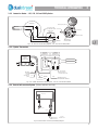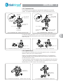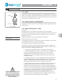
1
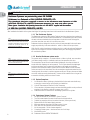
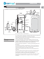
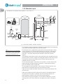
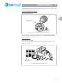
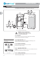
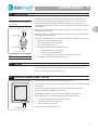
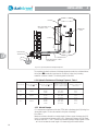
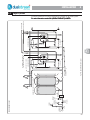
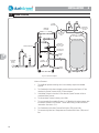
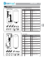
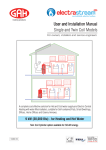
heating products Technical and Installation manual All Models For owners, installers and service engineers Important Health and Safety Information for Installers and Service Engineers Health and Safety at Work Act 1974 OTHER MATERIALS Consumer Protection Act 1987 SEALANTS, ADHESIVES AND PAINTS COSHH Regulations 1988 Sealants, Adhesives and Paints are used in the construction of the Dualstream components. When used in the manner for which they are intended they do not present any known hazard. The following information is given as a requirement of the above legislation. Great care is taken by GAH (HEATING PRODUCTS) LIMITED to ensure that Dualstream systems are designed and manufactured to meet general safety requirements when properly used and installed as recommended in this manual. It is the responsibility of Users and Engineers to ensure that adequate protective clothing and glasses are worn when working with the Dualstream system. SEALS AND INSULATION ELECTRIC All cylinders have electrical supply of 240V (enough to endanger life) connected to the Immersion Heater. Always isolate before adjustment, servicing and repair. All electrical installation and maintenance of the Dualstream must be carried out by a competent qualified installer. All electrical work must be installed to the requirements of these ‘User and Installation Instructions’. Insulation and sealing materials are used in the construction of the Dualstream cylinders. Units are sealed and when used in the manner for which they are intended the insulating and sealing materials do not present any known hazard. However always observe the following recommendations:1. Avoid inhalation of fibres or dust, wear face mask. 2. Avoid eye contamination by fibres or dust - wear eye protection. 3. As far as possible avoid any skin contact with Fibreglass Insulation, Glass Rope, Mineral Wool, Insulation Pads and Ceramic Fibre. In pursuance of a policy of constant development, GAH (HEATING PRODUCTS) LIMITED reserve the right to change any boiler part or design without notice, therefore certain details included in this manual may not be correct at the time of printing. Any modification and improvements detailed in this manual does not commit GAH to update any system previously supplied. Manual Part No. ...................015-15011 Manual Ref ......................... DS07 Issue ...................................4 Date .................................... Aug 2008 Patents GB 2349908 © 2008 GAH (HEATING PRODUCTS) LLTD. TD. rademark of GAH (HEATING PRODUCTS) LLTD. TD. Dualstream Dualstr eam is a TTrademark HTS REF HDUAL06 0206 23/02/06 Manual by Harber Technical Services Tel/Fax 01986 781605 E-mail:[email protected] www.harbertech.co.uk GAH (HEATING PRODUCTS) LIMITED will not accept responsibility for any damage or personal injury caused by not giving due consideration to the above safety recommendations. GAH (Heating Pr oducts) Ltd. Products) Building 846 Bentwaters Parks Rendlesham Woodbridge Suffolk IP12 2TW Tel: 01394 421160 Fax: 01394 421170 email: [email protected] www.gah.co.uk 33 CONTENTS CONTENTS Section 1 Intr oduction Introduction 1-1 Introduction ---------------------------------------------- 2 1 INTRODUCTION 1-2 System Layout ------------------------------------------- 3 1-3 System Requirements ------------------------------------ 4 Section 2 Operator Contr ols Controls 2-1 Hot Water Temperature - Heating System ---------------- 7 2-2 Hot Water Temperature - Immersion Heater --------------- 7 2 OPERA TOR CONTROLS OPERATOR 2-3 Hot Water Overheating ----------------------------------- 8 2-4 Shut Off Valves ------------------------------------------ 10 2-5 Expansion Relief----------------------------------------- 11 2-6 Servicing ------------------------------------------------ 11 2-7 Protech Anti-corrosion System -------------------------- 11 3 TECHNICAL INFORMA TION INFORMATION Section 3 TTechnical echnical Information 3-1 Specifications ------------------------------------------- 12 3-2 Dimensions --------------------------------------------- 13 3-3 Wiring --------------------------------------------------- 15 4 INST ALLA TION INSTALLA ALLATION Section 4 Installation 4-1 Building Control ----------------------------------------- 17 4-2 Installation ---------------------------------------------- 17 4-3 Expansion Discharge ------------------------------------ 20 4-4 Larger Systems ------------------------------------------ 22 4-5 System Pressure ---------------------------------------- 23 5 COMMISSIONING 4-6 Parts Supplied - ----------------------------------------- 24 Section 5 Commissioning 5-1 Commissioning Checks --------------------------------- 27 5-2 Handing Over ------------------------------------------- 28 6 SERVICING Section 6 Servicing 6-1 Routine Service ----------------------------------------- 29 Section 7 Fault Finding 7-1 Fault Finding -------------------------------------------- 30 7 FFAUL AUL T FINDING AULT IMPORTANT BEFORE STARTING THE INSTALLATION OF THE DUALSTREAM CHECK ALL COMPONENTS HAVE BEEN DELIVERED AND ARE IN SATISFACTORY CONDITION. 1 INTRODUCTION 1 1 1-1 Introduction Dualstream Systemss are protected by patent GB 2349908 Coldstr eam is a TTrademark rademark of GAH (HEATING PRODUCTS) LLTD. TD. Coldstream This Handbook has been compiled to assist in the Installation and Operation of GAH (HEATING PRODUCTS) LIMITED Dualstream domestic hot and cold water system. Please Ignor uctions rref ef Ignoree ‘Installation and Operating Instr Instructions ef.. 620-0027C 620-0027C’’ supplied with Accumulator Accumulator.. © 2008 GAH (HEATING PRODUCTS) LIMITED After installation the Installer of the system should give full operating instructions to the householder for the Dualstream System. Note It is recommended to obtain the nominal mains pressure and flow rate before installing a Dualstream system, this will enable the optimum system to be configured to suit conditions. 1-1.1 The Dualstream System The Dualstream systems by GAH Heating Products have been developed as an advanced solution for domestic hot and cold water installations. A Dualstream system will increase the water volume and maintain the mains pressure to both the hot and cold supplies, even when more than one outlet is in use at the same time. Dualstream has been designed to function on the minimum standard for domestic water supply as provided by local water authorities - which is 1 Bar at 9 litres per minute. GAH offer full technical assistance and design service to enable the optimum Dualstream system to be configured to overcome situations where poor mains supply and pressure are considered a problem. Note Direct cylinder heated by immersion heater. Indirect cylinder heated by boiler (also has immersion heater). Note For components supplied with system refer to page 24. 1-1.2 How the Dualstream system works The system mainly comprises:- an unvented direct or indirect cylinder, an accumulator (cold water storage vessel), a combination valve and an expansion relief valve. The accumulator has an internal controlled butyl diaphragm, incoming cold water is stored within this diaphragm at mains pressure. The air space between the diaphragm and the accumulator case is pressurised, this balances the supply and maintains pressure to the unvented hot water cylinder and cold outlets. When hot and cold water outlets are turned on the stored water from the accumulator supplements water from the incoming main, this results in consistent pressure and flow to all taps, showers and baths even when outlets are used simultaneously. Pressure will be sustained for as long as the accumulator is holding suffficient volume of water. 1-1.3 System Comprises 1. An unvented hot water cylinder pre-plumbed with all valves and controls with easy access pipe connections for quick, trouble-free installation. 2. Cylinder Thermostat and Thermal Cut-Out Thermostat. 3. An accumulator (cold water storage) and associated fittings which can be positioned anywhere in the dwelling, outhouse or garage, refer to 4-2.6. 4. A Motorised Valve for connection to the heating systems flow to cylinder. 1-1.4 Dualstream System Features 1. All taps and showers are at maximum ‘System Pressure’. 2. Provide increased water flow rate to both hot and cold water outlets. 3. Suitable for properties with very low mains flow rates (9 litres per minute). 4. Balanced Hot and Cold water supply pressures. 5. Minimum pressure drop when more than one tap is in use. 6. More than 25% less pipework than traditional systems. 7. No loft storage tank - no risk of water stagnation. 8. Completely sealed system - wholesome water to all cold taps. 9. No tank filling noise. 10. Dualstream utilises GREEN TECHNOLOGY. 2 INTRODUCTION 1 1-2 System Layout 1 1-2.1 Standard System All installations must comply with relevant regulations - refer to section 4-1. UNVENTED CYLINDER HOT WATER SUPPLY TO TAPS BALANCED COLD SUPPLY TO TAPS HTPV ACCUMULATOR COMBINATION VALVE OUTSIDE TAP KITCHEN SINK COLD TAP INCOMING MAINS SUPPLY SINGLE CHECK VALVE (If required) CHECK VALVE TUNDISH HEATING SYSTEM FILL PRV BOILER FLOW WATER SOFTENER DRAIN EXPANSION DISCHARGE BOILER RETURN DRAIN Fig. 1-2a Schematic Installation - Standard Arrangement Fig. 1:2a shows a typical configuration of a Dualstream system when the accumulator and hot water cylinder can be installed within close proximity of each other. Note This layout will, in practice, be found to be the most efficient. This installation method allows for the accumulator to take up expansion from the unvented cylinder, no further expansion vessels are required. The incoming mains supply is connected to the Combination Valve which is factory assembled to the unvented hot water cylinder. The Combination Valve has an integral check valve. A Single Check Valve is supplied, this is only required to be fitted if back syphonage is possible from any item fitted prior to the Combination Valve. Provision must be made, as applicable, for:- outside tap, boiler/heating system fill and water softener. The Combination Valve limits the incoming pressure to 3.5 bar, it has an integral non return valve and pressure relief valve (PRV). Once passed the Combination Valve the incoming mains water supplies the accumulator and the cylinder. Supply to all the cold taps and outlets is taken from the Tee fitting at the base of the accumulator. Supply to the hot taps and outlets is taken from the cylinder in the traditional manner. The cylinder HTP Valve and the combination valve PRV should be plumbed to the tundish (supplied), installation must comply with building regulations. Three full bore lever valves are supplied, it is recommended to install these, one each:incoming mains to combination valve, hot supply from cylinder, cold supply from accumulator. 3 INTRODUCTION 1 1-2.2 Alternative Layout 1 All installations must comply with relevant regulations - refer to section 4-1. UNVENTED CYLINDER ACCUMULATOR HOT WATER SUPPLY TO TAPS HTPV MAINS SUPPLY CHECK VALVE SPLIT COMBINATION VALVE OUTSIDE TAP KITCHEN SINK COLD TAP INCOMING MAINS SUPPLY SINGLE CHECK VALVE EXPANSION VESSEL BALANCED COLD SUPPLY TO TAPS PRV HEATING SYSTEM FILL BOILER FLOW WATER SOFTENER DRAIN DRAIN 3.5 Bar PRESSURE REDUCING VALVE BOILER RETURN EXPANSION DISCHARGE Fig. 1-2b Schematic Installation - Alternative Arrangement Fig. 1:2b shows a typical configuration of a Dualstream system when the accumulator has to be installed at a distance away from the hot water cylinder. Note The expansion vessel is not supplied with the Dualstream system. GAH Heating Products can supply expansion vessels if ordered with the Dualstream system. The Combination valve is supplied factory assembled to the unvented hot water cylinder. For this configuration it is recommended to split this valve and fit the 3.5 bar pressure reducing part of the valve on the incoming mains supply immediately after the single check valve. The PRV/non return valve part should be re-fitted to the cylinder as supplied. This installation method does not allow for the accumulator to take up expansion from the unvented cylinder, therefore a suitably sized independant expansion vessel must be fitted. This should be connected to the 6 Bar port of the PRV/non return valve part of the combination valve at the cylinder.. The incoming mains supply is connected to the accumulator. Provision must be made between the single check valve and the accumulater for:- outside tap, boiler/heating system fill and water softener, as applicable. The cold supply from the accumulator is connected to the PRV/non return valve, once passed this the incoming water supplies the accumulator and cylinder. Supply to all the cold taps and outlets is taken from the T fitting located under the PRV/ non return valve. Supply to the hot taps and outlets is taken from the cylinder in the traditional manner. The cylinder HTP Valve and the combination valve PRV should be plumbed to the tundish (supplied), installation must comply with building regulations. 4 Three full bore lever valves are supplied, it is recomended to install these, one each:incoming mains to the PRV/non return valve, hot supply from cylinder, cold supply to taps. INTRODUCTION 1 1-2.3 Typical Twin Coil Cylinder Layout 1 SOLAR COLLECTORS GAH (Heating Products) Ltd. supply a range of Solar Water Heating Systems that compliment the GAH Dualstream System. For further details consult GAH. SOLAR SYSTEM CONTROL AUXILIARY HEAT SOURCE (BOILER) UNVENTED TWIN COIL CYLINDER HTPV HOT WATER SUPPLY TO TAPS AUXILIARY HEAT SOURCE (BOILER) FLOW TWIN COIL CYLINDER BALANCED COLD SUPPLY TO TAPS ACCUMULATOR TYPICAL SOLAR WATER HEATING SYSTEM AUXILIARY HEAT SOURCE (BOILER) RETURN PRIMARY HEAT SOURCE (SOLAR) FLOW DRAIN All installations must comply with relevant regulations - refer to section 4-1. PRIMARY HEAT SOURCE (SOLAR) RETURN Fig. 1-2c Twin Coil Cylinder Application 1-3 System Requirements 1-3.1 Sizing of System The size of the Dualstream system is determined by the capacity of the accumulator and cylinder models selected. As the accumulator provides the pressure for the system it is important that this is of adequate size. The accumulator water content is up to 65% of its gross volume. Note The accumulator model is designated as its gross volume, the actual water content of the accumulator is up to 65% of its gross volume. When sizing the Dualsteam system close consideration should be given to the following:1. Incoming mains supply pipe size. 2. Incoming mains flow and static pressure. 3. House type, building height and number of occupants. 4. Typical daily water usage and peak demands. 5. Number of bathrooms and total number hot and cold water outlets 6. Types of shower, taps and baths and the volume and pressure of water to operate them. 5 INTRODUCTION 1 1 The following chart is given as a guide only. Flat Smaller House Small House Medium House Larger House Large House Kitchen 1-2 Bedrooms 1 Bath & Shower Kitchen Cloakroom 2-3 Bedrooms 1 Bath & Shower Kitchen, Cloakroom 4-5 Bedrooms 2 Baths & Showers Kitchen, Cloakroom Utility Room 4-6 Bedrooms 2 Baths & Showers Kitchens, Cloakrooms Utility Rooms Multiple Beds 4-5 Baths & Showers Preferred Accumulator Model 100 200 240 200 240 300 240 300 500 300 500 500 2 x 500 Preferred Cylinder Size 125 150 210 250 250 300 500 2 x 500 Size of Dwelling Usage Note The accumulator model is designated as its gross volume, the actual water content of the accumulator is up to 65% of its gross volume. GAH offer full technical assistance and design service to enable the optimum Dualstream system to be configured to overcome situations where poor mains supply and pressure are considered a problem. 1-3.2 Central Heating System The Dualstream system does not affect the central heating installation. However consideration has to be given to the best method of connection and control of the heating system to the indirect cylinder. 1-3.4 Scale Protection IMPORTANT All installations should have a scale protection device fitted and in areas known to have hard water, a water softening device is strongly recommended. GAH offer a range of quality Water Softeners, for information contact GAH (HEATING PRODUCTS). GAH recommend and promote the use of scale prevention devices and water softeners in areas that are known to have hard water. Installed correctly they prolong the life of equipment and help prevent lime-scale formation in the pipework. Water Softeners provide the advantages of soft water, as well as preventing scale build up on taps and shower heads. Water softeners and any mains fed system must be of adequate capacity and should be installed with suitably sized hoses to prevent any possibility of flow reduction. 1-3.5 Frost Protection When planning the installation location of both the accumulator and the unvented cylinder consideration must be given to the risk of frost and the use of frost protection. The design of the accumulator gives it a degree of frost protection enabling it to be located within the dwelling,loft space or garage without further protection. The cylinder can also be installed within the dwelling or loft space without further protection. Cylinders or accumulators must have frost protection when they are installed where low temperatures could be a potential problem. Cylinders can be protected by a frost thermostat. To comply with Building Regulations all necessary pipework must be suitably lagged. 6 OPERA TOR CONTROLS OPERATOR 2 2-1 Hot Water Temperature - Heating System 2-1.1 Hot Water Control - Heating System When the hot water is heated by the heating system the temperature of the hot water at the taps is controlled by the Cylinder Thermostat. This controls a motorised valve that opens and closes the flow from the heating system. Note For 500 Cylinders see 2-2.2. The temperature range is 30°C to 85°C. 2 Recommended setting is 60°C. MOTORISED VALVE LOWER HIGHER FLOW FROM HEATING SYSTEM CYLINDER THERMOSTAT SHOWN AT 60° APPROX. THERMAL CUT-OUT SAFETY THERMOSTAT DOUBLE POLE SWITCH IMMERSION HEATER WATER HEATER Fig. 2-1a Typical Hot Water Control 2-2 Hot Water Temperature - Immersion Heater 2-2.1 Hot Water Control 125, 150, 210 & 300 Cylinders When the hot water is heated by the electric Immersion Heater the temperature of the hot water at the taps is controlled by the Immersion Heater Thermostat. This is located under the black Immersion Heater cover. RESET The temperature range is 30°C to 85°C. Recommended setting is 60°C. Fig. 2-2a shows the approximate setting position for 60°C. The Immersion Heater has a Thermal Cut-Out, refer to 2:3.1. N 2 1 L WARNING ALWAYS ISOLATE THE IMMERSION HEATER BEFORE REMOVING COVER. When the cover is removed electrical live terminals are exposed. ADJUSTMENT Fig. 2-2a Immersion Heater Thermostat 7 OPERA TOR CONTROLS OPERATOR 2 2-2.2 Hot Water Control - 500 Cylinders When the hot water is heated by the electric Immersion Heater the temperature of the hot water at the taps is controlled by the Immersion Heater Thermostat which has an adjusting knob located on top of the plastic Immersion Heater cover. The temperature range is 30°C to 85°C. Recommended setting is 60°C. 2 Fig. 2-2b 500 Immersion Heater Adjustment 2-3 Hot Water Overheating 2-3.1 Water Heated by Heating System When the hot water is heated by the heating system a Thermal Cut-Out Thermostat prevents the water within the cylinder overheating. In the event of the water temperature within the cylinder reaching 90°C the thermostat will trip and close the motorised valve shutting off the flow from the heating system - see fig. 2-3a. The Thermal Cut-Out Thermostat is a manual reset type, this means it has a button that pops out when the thermostat has been tripped by overheating. MANUAL RESET BUTTON Fig. 2-3a Thermal Cut-Out Thermostat To reset the system after overheating allow time for the water to cool, or run off some hot water, then remove the plastic cap and press the Thermal Cut-Out Thermostat manual reset button. If the Thermal Cut-Out Thermostat trips more than once, switch off the heating system and Immersion Heater and contact your installer. 2-3.2 Water Heated by Immersion Heater When the hot water is heated by the Immersion Heater its integral Thermal Cut-Out Thermostat prevents the water within the cylinder overheating. The Immersion Heater Thermal Cut-Out Thermostat is a manual reset type, this means it has a small button that pops up when the thermostat has been tripped by overheating. To reset the system after overheating switch off the Immersion Heater, allow time for the water to cool, or run off some hot water. WARNING ALWAYS ISOLATE THE IMMERSION HEATER BEFORE REMOVING COVER. When the cover is removed electrical live terminals are exposed. 8 OPERA TOR CONTROLS OPERATOR 2 If the Immersion Heater Thermal Cut-Out Thermostat trips more than once, switch off the Immersion Heater and contact your installer. To reset 125,150, 210 & 300 Cylinders Isolate the Immersion Heater. 2 THERMAL CUT-OUT RESET 'BIPOLAR SAFETY' N 2 1 L Fig. 2-3b 125, 150, 210 & 300 Immersion Heater Thermal Cut-Out Remove the Immersion Heater cover and using a small screwdriver, press the 'Bipolar Safety' reset button - see fig. 2-3b. To reset 500 Cylinder Isolate the Immersion Heater. Remove the Immersion Heater cover and using a small screwdriver, press the 'S' reset button - see fig. 2-3c. THERMAL CUT-OUT RESET 'S' Fig. 2-3c 500 Immersion Heater Thermal Cut-Out 9 OPERA TOR CONTROLS OPERATOR 2 2-4 Shut Off Valves The Dualstream installation will have a number of shut off valves, the location of these will be dependent on the installation - fig. 2-4a shows a typical layout. 2 BALANCED COLD SUPPLY TO TAPS UNVENTED CYLINDER HTPV HOT WATER SHUT OFF VALVE ACCUMULATOR SUPPLY WATER SHUT OFF VALVE OUTSIDE TAP KITCHEN SINK COLD TAP BOILER FLOW WATER SOFTENER INCOMING MAINS SUPPLY STOP COCK HEATING SYSTEM FILL SINGLE CHECK VALVE (If fitted) DRAIN EXPANSION DISCHARGE BOILER RETURN DRAIN Fig. 2-4a Typical Shut Off Valve Locations COLD WATER SHUT OFF VALVE IMPORTANT Before closing ANY valve:1. Switch OFF the Electric Immersion Heater. 2. Turn OFF the Heating System. 2-4.1 Stop Cock Normally located at the point where the mains supply enters the dwelling. Shuts off the mains water supply to the dwelling. Note When opening the stop cock turn the valve fully open then close ½ turn, this prevents the valve sticking. CLOSED 2-4.2 Single Check Valve (If fitted) Normally located after the Stop Cock. Prevents water backfeeding to main. Shuts off the mains water supply to the dwelling. 2-4.3 Cold Water Shut Off Valve Normally located in the cold feed close to the accumulator. Shuts off the cold water to the taps. 2-4.4 Supply Water Shut Off Valve Normally located where the cold supply connects to the combination valve on the cylinder. Shuts off the cold supply to the Dualstream system. OPEN Fig. 2-4b Valves 10 2-4.5 Hot Water Shut Off Valve Normally located where the Domestic Hot Water feed comes from the cylinder. Shuts off the hot water to the taps. OPERA TOR CONTROLS OPERATOR 2 2-5 Expansion Relief Note At least the Tundish or discharge pipe should remain in view, do not box in or cover up either. AIR BREAK DISCHARGE PIPE Fig. 2-5a Tundish Note For more information see 4-3 The Dualstream installation has a TPR Valve normally mounted on the cylinder. In the event of the pressure within the system becoming too high, the TPR Valve will vent. A Tundish will be fitted in the system, this should be located in the same space or compartment as the hot water cylinder. This device provides an air break when pressure is being vented. When pressure is being vented water/steam will be evident at the Tundish and from the discharge pipe of the Tundish. Water will normally only discharge when there is an increase in pressure caused by loss of air pressure in the accumulator. In the event of water/steam being seen at the discharge pipe or Tundish do the following:1. Turn ON a hot tap to relieve the pressure. 2. Turn OFF the Electric Immersion Heater. 3. Turn OFF the Heating System. 4. Investigate possible cause for high pressure e.g:i Cylinder Thermostat is set too high. ii Restriction in hot water pipework. iii Loss of air pressure in the accumulator resulting in no expansion. 5. Contact the installer before restarting the system. 2-6 Servicing It is recommended the system is inspected by an approved engineer once per year. The service procedure is included in section 6-1.1. 2-7 Protech Anti-corrosion System - 500 only Fitted to TDI 500 & TDD 500 non stainless steel cylinders only. The Protech unit is an electronic anti-corrosion protection system which improves the life of the cylinder. The Protech unit must be permanently connected to a 240V supply at all times. The unit has a RED and a GREEN light on the front. The GREEN light should be on at all times, this indicates proper operation. When the RED light is on it indicates improper operation which could be:- Fig. 2-7a Protech Unit 1. A short circuit between the electrode and the cylinder. 2. One of the electrodes is not connected. 3. There is no water in the cylinder. Consult the installer if the RED light is on. 11 2 TECHNICAL INFORMA TION INFORMATION 3 3-1 Specifications 3-1.1 Cylinder Maximum Water Supply Pressure ..................................................................... 6.0 Bar Operating Pressure ........................................................................................... 3.5 Bar HTPR Valve ............................................................................................. 7.0 Bar/90°C Cylinder Thermostat ...................................................................... range 30°C to 85°C Recommended Setting ................................................................................. 60°C max Thermal Cut-Out ..................................................................................... fixed @ 90ºC Immersion Heater ........................................................................................................ Voltage ........................................................................................................ 240V Direct 125, 150, 210, 300 ....................................................................... 2 x 3kW 3 Indirect 125, 150, 210, 300 ..................................................................... 1 x 3kW 500 ......................................................................................................... 1 x 6kW Thermal Cut-Out ............................................................................. fixed @ 90°C Motorised Valve ................................................................................................. V4303 Protech Anti-corrosion unit - TDI 500 & TDD 500 only (non stainless steel only) ....... 240V 3amp 3-1.2 Accumulator Membrane ................................................................................. Butyl for potable water Maximum pressure .......................................................................................... 7.0 Bar Minimum pressure .................................................................................... 0.5/0.8 Bar Factory set pressure ............................................................................................ 2 Bar 3-1.3 Pipes All pipes should be sized to suit application. 3-1.4 Electrics All systems are supplied for 240V SINGLE PHASE. On 500 Cylinders the Immersion Heaters can be converted to 3 Phase - consult GAH (HEATING PRODUCTS) LIMITED for further information. Cylinder model I mmersion Heater Size Indirect TDI125 TDI150 TDI210 TDI250 TDI300 Indirect TDI500 240V 2 x 3k W 240V 1 x 3k W 240V 6k W Recommen ded Fu se Ratin g 2 x 13 amp 13 amp 30 amp Recommen ded Cable Size 2 x 2 .5 m m ² 2 .5 m m ² 6 .0 m m ² N/A N/A 240v Protech 12 Direct TDD125 TDD150 TDD210 TDD250 TDD300 Protech Recommen ded Cable Size N/A N/A 1 .5 m m ² Protech Recommen ded Fu se Ratin g N/A N/A 3 amp TECHNICAL INFORMA TION INFORMATION 3 3-2 Dimensions 3-2.1 Accumulator Dimensions PRE-CHARGE VALVE - SCHRAEDER 100 Essential Access Ø28 3 ØD H2 H TEE 28/28/28 COMPRESSION FITTING COMPRESSION FITTINGS BASE VENTED TO PREVENT CONDENSATION & FLOOR FIXING Accu mu lator Model Size (Gross Capacity) *Maximu m Water Con ten t ØD H H2 Recommen ded min imu m space requ ired. Weigh t Empty 100 100 u p to 65 litres 410m m 890m m 990m m 1 6 .3 k g 200 170 u p to 110 litres 535m m 940m m 1040m m 3 0 .4 k g 240 240 u p to 156 litres 535m m 1215m m 1315m m 3 7 .2 k g 300 310 u p to 198 litres 535m m 1500m m 1600m m 4 4 .5 k g 500 450 u p to 292 litres 668m m 1530m m 1630m m 6 9 .5 k g * Water content is up to 65% of the accumulator volume. Total weight = weight empty + water content @ 1kg/litre. Fig. 3-2a Accumulator Dimensions 13 TECHNICAL INFORMA TION INFORMATION 3-2.2 Standard Direct and Indirect Cylinder Dimensions COMPRESSION FITTINGS ARE SUPPLIED TO ADAPT THE CYLINDER TAPPINGS TO THE PIPE SIZES SHOWN. 800 ØB ØB 45° HOT WATER TO TAPS -28mm 22.5° 3 45° TPRV TPRV HOT WATER TO TAPS -22mm COLD MAINS SUPPLY IN -22mm A EXPANSION DISCHARGE E EXPANSION DISCHARGE BOILER FLOW -28mm A BOILER FLOW -22mm 500 maximum 500 maximum COLD MAINS SUPPLY IN -28mm COLD TO TAPS -28mm D D COLD TO TAPS -22mm BOILER RETURN -28mm C C BOILER RETURN -22mm 125,150, 210 & 300 CYLINDERS Capacity Coil Su r face Coil Ratin g A ØB C D E Weigh t E mp ty Weigh t Fu ll TDI 125 125 litres 0 .7 5 m ² 2 0 .5 k W 1015 Ø505 225 625 747 25k g 150k g TDI 150 150 litres 0 .9 m ² 2 6 .7 k W 1165 Ø505 225 765 905 30k g 180k g TDI 210 210 litres 0 .9 m ² 2 6 .7 k W 1495 Ø505 225 765 1221 40k g 250k g TDI 250 250 litres 1 .5 m ² 3 1 .8 k W 1555 Ø560 255 795 1316 47k g 297k g TDI 300 300 litres 1 .5 m ² 3 1 .8 k W 1795 Ø560 255 795 1551 50k g 350k g TDI 500 495 litres 1 .5 m ² 3 1 .8 k W 1870 Ø714 230 700 - 149k g 641k g TDD 125 125 litres - - 1015 Ø505 - - 747 21k g 146k g TDD 150 150 litres - - 1165 Ø505 - - 905 29k g 176k g TDD 210 210 litres - - 1495 Ø505 - - 1221 36k g 246k g TDD 250 250 litres - - 1555 Ø560 - - 1316 42k g 292k g TDD 300 300 litres - - 1795 Ø560 - - 1551 44k g 344k g TDD 500 495 litres - - 1870 Ø714 - - - 130k g 630k g Cylin der Model I N D I R E C T D I R E C T 500 CYLINDERS Fig. 3-2b Standard Cylinder Dimensions 14 3 TECHNICAL INFORMA TION INFORMATION 3 3-2.3 Indirect Twin Cylinder Dimensions COMPRESSION FITTINGS ARE SUPPLIED TO ADAPT THE CYLINDER TAPPINGS TO THE PIPE SIZES SHOWN. ØB 22.5° TWIN COIL CYLINDER ARE USED FOR SOLAR WATER HEATING APPLICATIONS SEE 1-2.3 45° TPRV HOT WATER TO TAPS -22mm 3 500 maximum BOILER FLOW -22mm COLD MAINS SUPPLY IN -22mm BOILER RETURN -22mm PRIMARY HEAT SOUCE FLOW (SOLAR) D E A EXPANSION DISCHARGE G F PRIMARY HEAT SOUCE FLOW (SOLAR) C COLD TO TAPS -22mm DI MENSI ONS Cylinder Model A ØB C D E F G I T S I 210 1495 Ø505 806 1206 1221 225 625 I T S I 250 1555 Ø560 876 1276 1316 255 655 I T S I 300 1795 Ø560 1111 1511 1551 255 795 Cylinder Model Capacity Weigh t Fu ll I T S I 210 Bottom Coil Top Coil Su r face Ratin g Su r face Ratin g Weigh t E mp ty 200 litres 0 .6 7 m ² 1 9 .0 k W 0 .6 7 m ² 1 9 .0 k W 29k g 239k g I T S I 250 250 litres 0 .6 7 m ² 1 9 .0 k W 0 .6 7 m ² 1 9 .0 k W 47k g 297k g I T S I 300 300 litres 0 .6 7 m ² 1 9 .0 k W 0 .9 0 m ² 2 6 .7 k W 49k g 349k g Fig. 3-2c Twin Cylinder Dimensions 15 TECHNICAL INFORMA TION INFORMATION 3-3 Wiring 3-3.1 Immersion Heater - 500 Cylinders 500 cylinders have three 2kW immersion heater elements (total 6kW) and must be wired using 3 x 2.5mm² 20amp Heat Resistant Cables as shown. THERMOSTAT With Thermal Safety Device 3 L1 B1 L2 B2 L3 B3 A1 A2 A3 IMPORTANT ENSURE ALL TERMINALS ARE TIGHT AND CORRECT EARTH TERMINAL BOTH PHIALS ARE INSERTED IN THIS HOLE 1 3 L1 L2 4 6 N3 N2 HEATING ELEMENTS 2 N1 L3 5 3 x 2.5mm² 20A 3-CORE HEAT RESISTANT CABLE blue blue blue AMP TAG CONNECTIONS 45 AMP DOUBLE POLE SWITCH 6mm² 32A 3-CORE brown L1 brown L2 L3 brown L 3 x 2.5mm² 20A 3-CORE HEAT RESISTANT CABLE 2 5 3 1 THERMOSTAT With Thermal Safety Device Fig. 3-3a Immersion Heater Wiring Diagram - 500 Cylinder 16 4 3 x 2kW HEATING ELEMENTS green/ yellow N 6 3 x LIVE WIRES supplied 3 TECHNICAL INFORMA TION INFORMATION 3 3-3.2 Immersion Heater - 125, 150, 210 and 300 Cylinders THERMOSTAT EARTH (green yellow) LIVE (brown) A R S AFE TY DOUBLE POLE SWITCH N 2 1 B IP OL IMMERSION HEATER L green/yellow 2.5mm 20A 3-CORE HEAT RESISTANT CABLE brown NEUTRAL (blue) LIVE blue NEUTRAL THERMOSTAT ADJUSTMENT 3 Fig. 3-3b Immersion Heater Wiring Diagram - 125, 150, 210 and 300 Cylinders 3-3.3 Cylinder Thermostats HIGH LIMIT THERMOSTAT Normally Closed CYLINDER THERMOSTAT Normally Closed HONEYWELL V4043H Normally Closed FLOW FROM BOILER NOT USED or BOILER or PUMP depending on system orange grey Not required. Can be used for hot water heated light brown blue green/yellow NEUTRAL orange EARTH SWITCHED LIVE from BOILER/HEATING CONTROLS Fig. 3-3c Cylinder Thermostats Wiring Diagram - 125, 150, 210 and 300 Cylinders 3-3.4 Protech Anti-corrosion System (500 non stainless steel only) Anode circuit L N Electronic anode Brown / Red Blue / Black 240V 3amp PERMANENT SUPPLY Fig. 3-3d Protech Anti-corrosion System Wiring Diagram 17 INST ALLA TION INSTALLA ALLATION 4 4-1 Building Control Note In some areas it is a criminal offence to install an unvented hot water storage system without notifying the local authority, or without the relevant licence. To install a Dualstream System the installer must be fully competent, suitably qualified and hold a relevant unvented certificate and any applicable licence that may be required by the local inspectorate for installation of an unvented hot water storage system. In some areas the Local Authority may require notification by means of a building notice or by the submission of full plans for the proposed installation of an unvented hot water storage system. 4-1.1 Regulations ent Building RRegulations egulations (paying particular attention to G3 The Water Byelaws and Curr Current and Part L 1 & 2) and HSE requirements should be considered when installing a Dualstream System. Note GAH offer full unvented training packages contact GAH (HEATING PRODUCTS). 4-1.2 Electrical Regulations ent IEE Wiring RRegulations. egulations. current All wiring should carried out to and comply with the curr All electrical work must comply with any rrelevant elevant rregulations egulations that apply at the time of the installation. 4 4-1.3 Electrical Work All electrical installation and maintenance of the Dualstream must be carried out by a competent qualified installer. All electrical work must be installed to the requirements of these ‘User and Installation Instructions’. 4-2 Installation 4-2.1 Unvented Hot Water Cylinder The cylinder may be installed at any convenient above ground location within the dwelling. As Dualstream is a sealed system, the cylinder is equally effective on any floor. The cylinder must always be installed vertically. Avoid positioning the cylinder where it may be subjected to frost. The floor must give adequate support to the filled cylinder. Cylinders with legs are supplied with self-tapping screws for floor fixing. For maintenance purposes leave at least 500mm at the front of the cylinder. The cylinder may be installed below ground i.e. in a basement, providing that the expansion relief discharge pipe is plumbed to a metal receptacle with a suitable pump and switch arrangement, current Building Regulations give details of this. An alternative is to use a Hepworth HepvO Self Sealing Waste Valve, this must be installed to the manufacturers specification and building regulations. 4-2.2 Cylinder Thermostat The combined Cylinder Thermostat and Thermal Cut-Out Thermostat supplied should be inserted into the socket provided in the cylinder. A screw is provided to clamp the unit in place. Fig. 4-2a Cylinder Thermostat 18 Wire the unit as wiring diagram 3-3c. INST ALLA TION INSTALLA ALLATION 4 4-2.3 Combination Valve The Combination Valve is supplied pre assembled with pipework to the unvented cylinder. For standard configurations as shown in 1:2.1 this should remain in situ. 22mm SUPPLY FROM MAINS 28mm SUPPLY FROM MAINS 3.5Bar PRESSURE REDUCING VALVE 3.5Bar PRESSURE REDUCING VALVE LINE STRAINER LINE STRAINER EXPANSION RELIEF Set at 6 bar 15mm TO TUNDISH 22mm TO TUNDISH 22mm SUPPLY TO CYLINDER AND ACCUMULATOR EXPANSION RELIEF Set at 6 bar Fig. 4-2b Combination Valve - Cylinders 125,150, 210, 300 28mm SUPPLY TO CYLINDER AND ACCUMULATOR Fig. 4-2c Combination Valve - Cylinders 500 For alternative systems as shown in 1:2.2, it is recommended to split the Combination Valve and fit the 3.5 Bar Reducing Valve section onto the incoming mains supply as shown in fig 1:2b. MAINS SUPPLY Fig. 4-2d Splitting Combination Valve - Cylinders 125,150, 210, 300 4 MAINS SUPPLY Fig. 4-2e Splitting Combination Valve - Cylinders 500 4-2.4 Expansion Vessel As the Dualstream Accumulator acts as the system expansion vessel, an independent expansion vessel system is not normally required. However, if the alternative Dualstream configuration shown in 1:2.2 is adopted or an independent expansion vessel (not supplied by GAH) is specified it should be fitted to the domestic hot water system. It is recommended to connect the expansion vessel to the Combination Valve which has a ¾ BSP port provided for this. The expansion vessel must always be open to the system with NO shut off or isolation valves in the connection pipe. ¾ BSP PORT FOR EXPANSION VESSEL ¾ BSP PORT FOR EXPANSION VESSEL Fig. 4-2f Expansion Vessel Connection - Cylinders 125,150, 210, 300 Fig. 4-2g Expansion Vessel Connection - Cylinders 500 19 INST ALLA TION INSTALLA ALLATION 4 4-2.5 Accumulator The accumulator may be installed at any convenient location within the dwelling, outhouse, garage, loft or basement. Note As Dualstream is a sealed system, the pressure at the taps is not affected by the height of the cold water storage. In normal circumstances the accumulator should be installed vertically. Where this is not possible accumulators up to 240 can be installed horizontally by supporting it in a cradle and ensuring provision is made to make it fully drainable. The floor must give adequate support to the filled accumulator. The accumulator must be protected from frost, particularly when it is sited in a loft, outhouse or garage. Note that space is required to the top of the vessel to access the pressure valve. Provision must be made to enable the accumulator to be drained when required. IMPORTANT The accumulator is supplied at 2 Bar pressure. It is recommended to set the pressure at 1.5 Bar below the mains pressure with a minimum of 0.5/0.8 Bar - see 4-5 and 5-5.1. 4-2.6 Scale Protection IMPORTANT All installations should have a scale protection device fitted and in areas known to have hard water, a water softening device is strongly recommended. 4 GAH offer a range of quality Water Softeners, for information contact GAH Heating Products. GAH recommend and promote the use of scale prevention devices and water softeners in areas that are known to have hard water. Installed correctly they prolong the life of equipment and help prevent lime-scale formation in the pipework. Water Softeners provide the advantages of soft water, as well as preventing scale build up on taps and shower heads. Water softeners and any mains fed system must be of adequate capacity and should be installed with suitably sized hoses to prevent any possibility of flow reduction. The location and position of the scale protection device or Water Softener should be as the manufacturers recommendations. 4-2.7 Pipework When all pipework has been installed, disconnect from the Dualstream components and flush all pipework thoroughly. When connecting to existing pipework remove all unwanted components, create new pipe runs then flush thoroughly before connecting to the Dualstream components. 4-2.8 Dualstream Components All Dualstream components and pipework are checked at the factory prior to dispatch, however always check the connections for leaks on commissioning as transportation and installation can cause joints to move. 20 INST ALLA TION INSTALLA ALLATION 4 4-3 Expansion Discharge AIR BREAK DISCHARGE PIPE 4-3.1 Tundish The Tundish must be vertical and fitted within 500mm of the temperature and pressure relief valve and must be located with the cylinder. The tundish must also be in a position visible to the occupants, and positioned away from any electrical devices. The discharge pipe from the tundish should terminate in a safe place where there is no risk to persons in the vicinity of the discharge and to be of metal. 4-3.2 Expansion Discharge - Self Sealing Valve A Hepvo Self Sealing Valve is available as an option, this enables alternative discharge arrangements to be used, however its use and installation must be approved by the local building control. Fig. 4-3a Tundish 4-3.3 Expansion Discharge Pipe - To Gully See Fig.4-3b Discharge pipes from the temperature TPRV and PRV may be joined together. Note The TPRV and PRVs must not be used for any other purpose. The pipe diameter must be at least one pipe size larger than the nominal outlet size of the safety device, this is adequate when the hydraulic resistance does not exceed that of a straight pipe 9m long. Bends must be taken into account in calculating the flow resistance. Minimum pipe sizes are given in Table 1. The discharge pipe must have a vertical section of pipe at least 300mm in length, below the tundish before any elbows or bends in the pipework. The discharge pipe must be installed with a continuous fall. The discharge must be visible at both the tundish and the final point of discharge, but where this is not possible or practically difficult; there should be clear visibility at one or other of these locations. Examples of acceptance are:1. Ideally below a fixed grating and above the water seal in a trapped gully. 2. Downward discharges at a low level; i.e. up to 100mm above external surfaces such as car parks, hard standings, grassed areas etc. These are acceptable providing that where children may play or otherwise come into contact with discharges, a wire cage or similar guard is positioned to prevent contact, whilst maintaining visibility. 3. Discharges at high level; i.e. into a metal hopper and metal downpipe with the end of the discharge pipe clearly visible (tundish visible or not); or onto a roof capable of withstanding high temperature discharges of water 3m from any plastic guttering systems that would collect such a discharge (tundish visible). WARNING Scalding water and steam can be blown out of the discharge pipe. Position the discharge so that it is not a hazard to property or people (especially children). 4. Where a single pipe serves a number of discharges, such as in blocks of flats, the number served should be limited to not more than 6 systems so that any installation can be traced reasonably easily. The single common discharge pipe should be at least one pipe size larger than the largest individual discharge pipe to be connected. If unvented hot water storage systems are installed where discharges from safety devices may not be apparent i.e. in dwellings occupied by blind, infirm or disabled people, consideration should be given to the installation of an electronically operated device to warn when discharge takes place. Note: The discharge will consist of scalding water and steam. Asphalt, roofing felt and nonmetallic rainwater goods may be damaged by such discharges. 21 4 INST ALLA TION INSTALLA ALLATION 4 TPR VALVE METAL DISCHARGE PIPE D1 TO TUNDISH - 15mm 500 max COMBINATION VALVE 300 min TUNDISH FIXED GRATING TRAPPED GULLY 4 CONTINUOUS FALL DISCHARGE PIPE D2 - METAL FROM TUNDISH Fig. 4-3b Typical Expansion Discharge Arrangement The equivalent hydraulic resistance of discharge pipework needs to be calculated where the length of D2 exceeds 9m (maximum for one step up in pipe size) including resistance of elbows or bends. The following table can be used: 4-3.4 Hydraulic Resistance of Discharge Pipework - Table 1 Maxi mum resi stance allowed Mi ni mum si ze of di scharge pi pe expressed as a length of strai ght from Tundi sh (D2 D 2) pi pe, i .e. no elbows or bends Valve outlet si ze Mi ni mum si ze of di scharge to Tundi sh (D1 D 1) G½ 15 mm 22 mm 28 mm 35 mm up to 9 m up to 18 m up to 27 m 0.8 m 1.0 m 1.4 m G¾ 22 mm 28 mm 35 mm 42 mm up to 9 m up to 18 m up to 27 m 1.0 m 1.4 m 1.7 m G1 28 mm 35 mm 42 mm 54 mm up to 9 m up to 18 m up to 27 m 1.4 m 1.7 m 2.3 m Resi stance created by each elbow or bend 4-3.5 Worked Example G ½ temperature and pressure relief valve (TPRV) with a discharge pipe (D2) having four elbows and length of 7m from the tundish to the point of discharge. From Table 1:Maximum resistance allowed for a straight length of 22mm copper discharge pipe (D2) from G ½ temperature and pressure valve is 9m. Subtract the resistance for four 22mm elbows at 0.8m each = 3.2m. Therefore the maximum permitted length equates to 5.8m - as 5.8m is less than the actual length of 7m therefore pipe D2 must be 28mm. 22 STOP COCK INCOMING MAINS SUPPLY DOUBLE CHECK VALVE (If required) ACCUMULATOR 1 ACCUMULATOR 2 BALANCED COLD SUPPLY TO TAPS WATER SOFTENER HEATING KITCHEN SYSTEM SINK COLD FILL TAP OUTSIDE TAP FOR REFERENCE ONLY Fig. 4-4a Typical Multi System Layout EXPANSION DISHARGE CYLINDER 1 HTPV EXPANSION VESSEL HOT SUPPLY TO TAPS CYLINDERS CONNECTED VIA SECONDARY RETURN PORT HTPV CYLINDER 2 EXPANSION VESSEL BOILER RETURN BOILER FLOW INST ALLA TION INSTALLA ALLATION 4 4-4 Larger Systems For larger systems two or more accumulators and cylinders can be linked together. For mor moree information consult GAH (HEATING PRODUCTS) LIMITED. 4 23 INST ALLA TION INSTALLA ALLATION 4 4-5 System Pressure SYSTEM PRESSURE BALANCED COLD SUPPLY TO TAPS UNVENTED CYLINDER HOT WATER SUPPLY TO TAPS HTPV ACCUMULATOR PRESSURE REDUCING VALVE (set at 3.5 Bar) MAINS PRESSURE INTEGRAL NON RETURN VALVE PRV -6 Bar 4 BOILER FLOW SYSTEM PRESSURE INCOMING MAINS SUPPLY DRAIN BOILER RETURN DRAIN Fig. 4-5a Pressure Diagram Notes on Pressures:- 24 1. The additional pressure reducing valve is not normally required on standard systems. 2. The Combination Valve has an integral pressure reducing valve fixed at 3.5 bar therefore the System Pressure will be 3.5 bar maximum. 3. If the Mains Pressure is less than 3.5 bar then the System Pressure will be at maximum Mains Pressure. 4. The Accumulator Pressure is factory set at 2 Bar. 5. The recommended Accumulator Pressure is 1.5 Bar below the mains pressure with an absolute minimum of 0.5/0.8 Bar - consult GAH Heating Products for further information. Also refer to 5-1.1. 6. The Combination Valve has a Pressure Relief Valve (PRV) set at 6 Bar. 7. The unvented cylinder has a Temperature and Pressure Relief Valve (PRV) set at 6 Bar. INST ALLA TION INSTALLA ALLATION 4 4-6 Parts Supplied 4-6.1 All models except 500 Item 1 3 7 8 6 2 5 4 Part Qt y Notes 1 Cyli nder 1 Pre-plumbed c/w Immersi on Heater 2 Cyli nder Feet 3 Complete wi th 6 screws 3 Accumulator 1 Pre-plumbed - 28mm compressi on 4 Motori sed Valve 1 For boi ler flow to cyli nder 5 Cyli nder Stat Thermal Overload Stat 1 For cyli nder 6 M.I. Coupler 22mm x ¾"BSP 2 For cyli nder boi ler Flow and Return 7 22mm Si ngle Check Valve 1 For i ncomi ng mai ns 8 22mm Ball Valves 3 1 for domesti c hot water 1 for domesti c cold water 1 for cold feed to the cyli nder 4-6.2 500 Only Item 3 1 8 7 4 5 Qty. Notes 1 Cyli nder 1 Pre-plumbed c/w Immersi on Heater 2 Cyli nder Feet 3 Suppli ed fi tted to Cyli nder 3 Accumulator 1 Pre-plumbed -28mm compressi on 4 Motori sed Valve 1 For boi ler flow to cyli nder 5 Cyli nder Stat & Thermal Overload Stat 1 For cyli nder 6 F.I. Coupler 28mm x 1"BSP 3 2 for cyli nder boi ler Flow and Return 1 for cold feed to cyli nder 7 28mm Si ngle Check Valve 1 For i ncomi ng mai ns 8 28mm Ball Valves 3 1 for domesti c hot water 1 for domesti c cold water 1 for cold feed to the cyli nder 6 2 Part 25 4 INST ALLA TION INSTALLA ALLATION 4-6.3 Connections to Dualstream - 125, 150, 210 and 300 Cylinders UNVENTED CYLINDER FROM MAINS 22mm HTPR VALVE DOMESTIC HOT WATER 22mm DOMESTIC COLD WATER 22mm DHW COMBINATION VALVE ACCUMULATOR MOTORISED VALVE SECONDARY DOMESTIC HOT WATER (PLUGGED) 4 BOILER FLOW 22mm TUNDISH DISCHARGE CYLINDER THERMOSTAT CYLINDER DRAIN COCK BOILER RETURN 22mm TO ACCUMULATOR 22mm ACCUMULATOR DRAIN COCK TO BE FITTED COLD INTO CYLINDER Domestic Hot Water 22mm Fit 22mm ball valve - supplied Domestic Cold Water 22mm Fit 22mm ball valve - supplied Mains supply 22mm Fit 22mm ball valve - supplied Tundish - Discharge to be arranged and sized to comply with Building Regulations. Boiler Flow 22mm Indirect only 22 x ¾ M.I. Coupler - supplied Fit Motorised Valve - supplied Boiler Return 22mm Indirect only 22 x ¾ M.I. Coupler - supplied Fig. 4-6a Typical Dualstream Connections 26 4 INST ALLA TION INSTALLA ALLATION 4 4-6.4 Connections to Dualstream - 500 Cylinder DOMESTIC HOT WATER 28mm DHW FROM MAINS 28mm DOMESTIC COLD WATER 28mm TPR VALVE ACCUMULATOR SECONDARY DOMESTIC HOT WATER (PLUGGED) COMBINATION VALVE 4 TUNDISH DISCHARGE BOILER FLOW 28mm MOTORISED VALVE CYLINDER THERMOSTAT COLD INTO CYLINDER CYLINDER DRAIN COCK TO ACCUMULATOR 28mm ACCUMULATOR DRAIN COCK TO BE FITTED BOILER RETURN - 28mm Domestic Hot Water Domestic Cold Water Mains supply Tundish Boiler Flow 28mm 28mm 28mm 28mm Boiler Return 28mm Fit 28mm ball valve - supplied Fit 28mm ball valve - supplied Fit 28mm ball valve - supplied Discharge to be arranged and sized to comply with Building Regulations. Indirect only 28 x ¾ M.I. Coupler - supplied Fit Motorised Valve - supplied Indirect only 28 x ¾ M.I. Coupler - supplied Fig. 4-6b Typical Dualstream Connections 27 COMMISSIONING 5 5-1 Commissioning Checks IMPORTANT It is the responsibility of the installer to ensure that the Dualstream System is properly commissioned. Should the commissioning not be carried out, then the manufacturers guarantee and any extended warranty, will become null and void. The Guarantee Form MUST be completed and returned to GAH (HEATING PRODUCTS) in the prepaid envelope provided. 5-1.1 Commissioning Procedure 1. Check accumulator pressure is 1.5 Bar below the mains pressure - minimum 0.5 Bar. 2. Check the Tundish is correctly installed to conform to the Building Regulations G3. 3. Check all pipe connections are tight and no joints have been left unsoldered. 4. Check ALL drain cocks are closed. 5. Check ALL wiring connections have been made. 6. Check the required earth continuity conductors have been fitted. 7. Check the Immersion Heater has its cover and gasket fitted and is tight in the cylinder. 8. Check the Immersion Heater is set to 60°C. 9. If fitted, check that the Scale Protection device or Water Softener has been fitted according to manufacturers instructions. 10. Open all shut off valves. 11. Turn on Mains Stop Cock and allow the system to fill. 5 12. Open all domestic taps in turn to purge air. 13. Check system for leaks including around the Immersion Heater. 14. Check the installation of the tundish complies with the Building Regulations. 15. Check no water is discharging from the Pressure Relief Valve or the TPR valve, this will be evident at the Tundish. 16. Test the operation of the TPR Valve by turning the manual test cap and ensure the water flows freely and safely to waste. 17. Test the operation of the Combination Valve by turning the manual test cap and ensure the water flows freely and safely to waste. 18. Set Cylinder Thermostat to 60°C (not required on 500 Cylinders). The Boiler and heating system should be checked before continuing. 19. (Indirect) Check heating system has correct type of motorised valve fitted and wired correcly to the cylinder flow. 20. Set Motorised Valve to Manual, open and allow the heat coil to fill. 21. Set the Motorised Valve to Auto. 22. Switch on the heating system. 23. Wait for the system to heat up. 24. Check temperature of hot tap water max. 60°C. 25. Check operation of cylinder thermostat. When turned down below tank temperature the motorised valve should open. When turned up above tank temperature the motorised valve should close. 26. Check for leaks again when the system is up to temperature. 27. Fill in details in the Benchmark Logbook. 28 COMMISSIONING CAUTION The main supply must be turned OFF and water drained from the Accumulator before lowering the charge pressure, failure to do so could result in damage to the diaphragm. Also refer to 4-2.5 and 4-5. If in doubt consult GAH Heating Products. 5 5-1.1 Accumulator Pressure Accumulators are supplied by GAH with a preset air charge of 2 Bar (28/30psi). The Combination Valve supplied with the Dualstream system has an integral pressure reducing valve fixed at 3.5 Bar. Therefore there is a pressure differential of 1.5 bar between the system pressure and the air charge of the Accumulator. When the incoming mains pressure is less than 3.5 Bar the pressure differential will be higher than 1.5 Bar and the Accumulator will not fill sufficiently, therefore it may be necessary to lower the Accumulator air charge pressure. The procedure for changing the Accumulator pressure is given below, this can be done before the system has been filled. It may be done after the system has been filled and tested, providing the incoming main has been turned OFF and the water drained from the Accumulator. Failure to do this may result in false pressure reading and damage to the butyl diaphragm. If mains pressure is 3.5 Bar or above changing the Accumulator charge pressure will not be necessary. Adjusting Air Pressure 1. Record mains pressure. 2. Turn main supply OFF. 3. Turn on cold outlets to empty Accumulator. 4. Remove black cap from top of Accumulator check/confirm Accumulator pressure with pressure gauge. 5. Lower air charge so that is 1 to 1.5 Bar below mains pressure. Minimum Accumulator pressure is 0.5 bar to 0.8 Bar. AIR CHARGE VALVE - SCHRADER 5 BUTYL DIAPHRAM Fig. 5-1a Accumulator 5-2 Handing Over Complete the Guarantee Form, the top sheet of this MUST be sent to GAH (HEATING PRODUCTS) LIMITED. Complete the Benchmark Logbook. The Installer should re-check the system and ensure it is completely satisfactory before demonstrating to the householder. The householder should be aware of the following:1. How to set the temperature of the tap hot water. 2. The function of the Pressure Relief Valve and Combination Valve and that over pressure will cause steam and scalding water to be emitted from the discharge pipe. 3. The Tundish is supplied as a visual identification for over pressure. 4. The procedure to follow in the event of over pressure. Refer to 2-5. This manual and supplements must be left with the householder together with a copy of the completed Guarantee Form. 29 SERVICING 6 6-1 Routine Service The Dualstream system should have a routine service at least once in 12 months. IMPORTANT Always turn off the heating system and electricity supply to the Dualstream before working on the Dualstream System. IMPORTANT Also carry out any service requirements of specific components as specified by the manufacturers instructions. Note If heavy scaling is evident then descaling the system is recommended. Ensure system is fully flushed following descaling. 6-1.1 Service Procedure 1. Confirm with customer service history and locate Benchmark Logbook. 2. Check cylinder model and serial number is listed in the Benchmark Logbook. 3. Visually inspect cylinder/s for damage, metal failure and signs of leaks. 4. Visually inspect accumulator for damage, metal failure and signs of leaks. 5. When applicable visually inspect expansion vessel and its pipework for damage, metal failure and signs of leaks. 6. Visually inspect all Dualstream pipework for damage, metal failure and signs of leaks. 7. Record mains pressure and system pressure. 8. Turn the Heating System OFF. 9. Turn the electrical supply to the Dualstream OFF. 10. Momentarily open the combination TPR Valve and check that the water drains freely and safely to and from the tundish. 11. Open cylinder TPRV for 15 seconds and close, valve should shut off. Repeat if valve sticks. If valve will not shut off replace valve. 12. Open combination PRV for 15 seconds and close, valve should shut off. Repeat if valve sticks. If valve will not shut off replace valve. 13. Close the Stop Cock. 14. Open the hot and cold taps, attach a hose to the cylinder and accumulator drain cocks and empty the system. 15. Check the pressure of the accumulator, this should be 1.5 Bar below the mains pressure with an absolute minimum of 0.5/0.8 Bar. 16. Remove Immersion Heater, remove limescale and examine the element. In hard water areas it is probably better to replace the Immersion Heater if heavily scaled. Refit Immersion Heater with gasket. 17. Most glass lined cylinders will have at least one magnesium anode, remove and inspect all anodes, replace if required. 18. Clean and check the line strainer in the combination valve - replace if required. 19. Check and clean the expansion relief valve in the combination valve - replace if required. 20. Close all drain cocks and refill system. 21. Check that no water is passing through the Combination Valve or the Pressure Relief Valves, this will be evident at the Tundish. 22. Switch on the heating system. 23. Check operation of motorised valve by setting heating system to call for hot water. The valve should open. Then turn hot water off - the valve should close. 24. Wait for the system to heat up. 6 25. Check temperature of tap water adjust as required, max. 60°C. 26. Check operation of cylinder thermostat. When turned down below tank temperature the motorised valve should open. When turned up above tank temperature the motorised valve should close. 27. Check for leaks again when the system is up to temperature. 30 28. Enter details of service into the Benchmark Logbook. FAUL T FINDING AULT 7 7-1 Fault Finding - also see www.gah.co.uk No COLD Water Supply Reduced Pressure No Hot Water 1. 2. 3. Check the mains supply has not been interrupted from the main. Check the stop cock and all valves on the mains supply are correctly installed. Check the stop cock and any valves on the mains supply are fully open. 1. 2. 3. Check the stop cock and any valves on the mains supply are fully open. Check the combination valve line strainer is not blocked - clean if required. Check line strainers and any other fittings are not blocked - clean if required. 1. Check there is power to the indirect heating system/boiler and/or the cylinder immersion heater. Check fuses for indirect heating system and/or the cylinder immersion heater. Check cylinder thermostat is installed and set correctly. 2. 3. Water Leaks Poor Flow Rate at Taps Good volume which falls away too quickly Cold water discoloured Hot water discoloured Please consult your installer. In the unfortunate event of a water leak from the Dualstream cylinder or accumulator, TURN OFF ELECTRIC SUPPLY, then turn off the mains water supply to the house via the stop cock. Make allowance to store some cold water for necessities. Open both cold and hot taps to drain the cylinders of water thus preventing any further leaks and consult your installer. 1. 2. 3. 4. Check to ensure combination valve filter is not blocked. Check all isolation valves are fully open. Check accumulator charge pressure is not too high - refer to 4-4. Check pipework from accumulator is of adequate size. 1. Check accumulator charge pressure is not set too high. Re-set pressure as section 4-4. 1. 2. 3. Check to make sure there is air in the accumulator. If air is not present, suspect faulty accumulator, consult GAH (HEATING PRODUCTS). Check mains supply - it may have been interrupted. Check water softener (when fitted) is operating correctly. 1. Indirect cylinder coils may be fractured, consult GAH Heating Products. 7 31 Notes 32 heating products GAH (Heating Products) Ltd. Building 846, Bentwaters Parks, Rendlesham, Woodbridge, Suffolk IP12 2TW www. gah.co.uk Tel: 01394 421160 Fax: 01394 421170 email: [email protected]