1
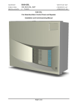
EQUIPMENT: DUO-CEL WRITTEN BY: RKP PUBLICATION: OM_DUO-CEL_USER CHECKED BY: AJC ISSUE No. & DATE: 1 APPROVED BY: JBJ 13/10/10 DUO-CEL Fire Detection/Alarm Control Panel and Repeater User Operation Manual DANGER THIS EQUIPMENT CONTAINS HAZARDOUS VOLTAGES THAT CAN CAUSE DEATH, SERIOUS PERSONAL INJURY, OR EQUIPMENT DAMAGE. THIS EQUIPMENT CONTAINS NO USER-SERVICEABLE PARTS. DO NOT REMOVE THE FRONT COVER. REFER ALL MAINTENANCE TO SUITABLY QUALIFIED PERSONNEL. PAGE 1 of 6 EQUIPMENT: DUO-CEL WRITTEN BY: RKP PUBLICATION: OM_DUO-CEL_USER CHECKED BY: AJC ISSUE No. & DATE: 1 13/10/10 List of Contents 1. INTRODUCTION ..............................................................................................................................................................3 2. USER OPERATION - FIRE AND FAULT CONDITIONS ...........................................................................................3 2.1 IF A FIRE IS DETECTED: ...............................................................................................................................................3 2.2 TO SILENCE THE FIRE ALARM SOUNDERS: ..................................................................................................................3 2.3 TO RESOUND THE FIRE ALARM SOUNDERS AFTER SILENCING:....................................................................................3 2.4 TO RESET THE PANEL FROM A FIRE ALARM: ..............................................................................................................3 2.5 TO OPERATE THE FIRE ALARM SOUNDERS IN EVACUATE MODE: ................................................................................3 2.6 IF A FAULT IS DETECTED: ...........................................................................................................................................3 2.7 TO SILENCE THE BUZZER: ..........................................................................................................................................3 2.8 SYSTEM FAULT INDICATION: .....................................................................................................................................3 2.9 USER ACTIONS IN THE EVENT OF A FAULT: .................................................................................................................4 3. PANEL OPERATION. .......................................................................................................................................................4 3.1 DISABLEMENT & TEST CONDITIONS ..........................................................................................................................4 3.1.1 To test, disable or re-enable one or more circuits: .........................................................................................4 3.1.2 To view only the disabled circuits: ..................................................................................................................4 3.1.3 To view only the circuits in test: ......................................................................................................................4 3.2 DISPLAY TEST............................................................................................................................................................4 4. DUO-CEL REPEATER PANEL OPERATION ..............................................................................................................4 5. ROUTINE TESTING AND MAINTENANCE ................................................................................................................4 6. USER RESPONSIBILITIES .............................................................................................................................................4 7. DUO-CEL USER INDICATIONS ....................................................................................................................................5 7.1 USER INDICATIONS ....................................................................................................................................................5 7.2 USER CONTROLS ........................................................................................................................................................6 PAGE 2 of 6 EQUIPMENT: DUO-CEL WRITTEN BY: RKP PUBLICATION: OM_DUO-CEL_USER CHECKED BY: AJC ISSUE No. & DATE: 1 13/10/10 1. Introduction This document contains the necessary information for operating the DUO-CEL Conventional Fire Detection control panel. 2. User Operation - Fire and Fault Conditions 2.4 To reset the panel from a Fire Alarm: This panel is capable of operating the fire alarm sounders in various ways: Sounder circuits can operate per zone or all together. Sounder circuits can be continuous or pulsed. All users should be fully aware of the particular configuration of their system and should have received training in the basic operation of the system. The following information is provided as a quick reference guide only. 2.5 To operate the fire alarm sounders in Evacuate Mode: 2.1 If a fire is detected: On the DUO-CEL Fire Alarm Panel: o The general Fire LED will flash and the buzzer will sound o The relevant zone Fire LED(s) will flash, indicating the location of the fire. o The Fire Signal output and LED will operate. o The Fire Alarm sounders will operate immediately (pulsed or continuous, zonally or together, as per configuration). o The Fire Relay will operate immediately Locate the source of the fire alarm (an LED will be visible on the detector which has been activated). Turn the Access Key to the vertical position. Press the Silence/Resound Alarms button once only. The fire alarm sounders will become silent. The General Fire LED and the Zone Fire LED(s) will become steady. Remove the Access Controls Key to lock the controls. 2.3 To Resound the fire alarm sounders after silencing: Turn the Access Controls Key on the panel door to the vertical position. Press the Silence/Resound Alarms button once only. Remove the Access Controls Key to lock the controls. Turn the Access Controls Key on the panel door to the vertical position. Press the Evacuate button. The Alert/Evac LED will illuminate and the panel buzzer will operate. All fire alarm sounders will operate continuously. Press the Silence/Resound Alarm button to silence the fire alarm sounders and clear the Alert/Evac LED. Remove the Access Controls Key to lock the controls. 2.6 If a fault is detected: 2.2 To Silence the fire alarm sounders: After the fire has been extinguished, turn the Access Controls Key on the panel door to the vertical position. Press the Reset button. The General Fire LED and the Zone Fire LED(s) will clear. Remove the Access Controls Key to lock the controls. The panel buzzer will sound. The General Fault LED will flash. One or more fault LEDs will flash; identifying which element of the system is faulty. When the fault is corrected the fault indication will clear automatically, except for the Fuse Failed indication, which requires the Reset button to be pressed. 2.7 To Silence the Buzzer: Press the Silence Buzzer button. The buzzer will silence. 2.8 System Fault Indication: In the event of a complete system failure, a System Fault will be indicated: The SYSTEM FAULT and GENERAL FAULT LED illuminate. All other LEDs will be extinguished. The internal buzzer will sound continuously. Warning. In this condition the panel is not functional and fire alarm cover is no longer available. PAGE 3 of 6 EQUIPMENT: DUO-CEL WRITTEN BY: RKP PUBLICATION: OM_DUO-CEL_USER CHECKED BY: AJC ISSUE No. & DATE: 1 13/10/10 2.9 User actions in the event of a fault: Determine the area affected by the fault and decide whether special actions (such as fire patrols) are needed in that area. Call your service engineer immediately. Record the event in the system log book. 3. Panel Operation. 3.1 Disablement & Test Conditions Each zone circuit can be disabled or placed into the test mode individually. All sounder circuits can be disabled or placed into the test mode as a group. The Fire Signal output can be disabled or placed into test mode. 3.1.1 To test, disable or re-enable one or more circuits: 1. Turn the Access Key to the vertical position. 2. Press the Select button to enter the Select Mode. The Controls On LED will flash. The cursor indication will pulse rapidly on the yellow Zone 1 fault LED. The yellow fault LED for any circuit currently in test or disabled will be illuminated. 3. Press the Select button to move the cursor to the required circuit fault LED. For each circuit the cursor is on, the General Disablement & General Test LEDs will indicate the current status for that circuit: i. General Test & General Disablement LEDS OFF: - Circuit is in normal operating mode. ii. General Test LED pulsing: - Circuit is in Test mode. iii. General Disablement LED pulsing: Circuit is Disabled. 4. To change the status of the selected circuit, press the Disable or Test button as required: Circuit is currently not disabled or in test: Press the Disable button to disable, Press the Test button to test. Circuit is currently disabled: - Press the Disable button to re-enable, Press the Test button to test (the disabled condition will also be cleared). Circuit is currently in test: - Press the Test button to clear the test, press the Disable button to disable (the test condition will also be cleared). 5. To exit from the Select mode, either remove the Access Controls Key to lock the controls or press the Select button repeatedly to scroll the flashing cursor through the remaining circuits until the Controls On LED stops flashing and the flashing cursor is cleared. 3.1.2 To view only the disabled circuits: 1. Turn the Access Key to the vertical position. 2. Press and hold the Disable button. Only the General Disablement LED and the fault LEDs of any disabled circuits will be illuminated. 3. Release the Disable button to return the display to normal. 3.1.3 To view only the circuits in test: 1. Turn the Access Key to the vertical position. 2. Press and hold the Test button. Only the General Test LED and the fault LEDs of any circuits in test will be illuminated. 3. Release the Test button to return the display to normal. 3.2 Display Test 1. Remove the Access Controls Key to lock the controls. 2. Press the Test button. All LEDs on the display will illuminate and the internal buzzer will sound for 5 seconds. 4. DUO-CEL Repeater Panel Operation The repeater panel operation is identical to the Alarm panel except that the disablement & Test facilities cannot be controlled from the repeater. The display is similar but the Disable and Select buttons are not present. 5. Routine Testing and maintenance See DUO-CEL Log Book for details. 6. User responsibilities PAGE 4 of 6 See DUO-CEL Log Book for details. EQUIPMENT: DUO-CEL WRITTEN BY: RKP PUBLICATION: OM_DUO-CEL_USER CHECKED BY: AJC ISSUE No. & DATE: 1 13/10/10 7. DUO-CEL User Indications This section gives an overview of the functions available to the end user. 7.1 User Indications Indicator General Indicator Section Operating Condition Colour Supply On General Fire General Fault General Test General Disablement Green Red Yellow Yellow Yellow Alert/Evac On Red Fire Signal On Red Fire Signal Flt / Dis / Tst Yellow Sounder Flt / Dis / Tst Yellow System Fault Yellow PSU Fault Yellow Fuse Failed Yellow Earth Fault Repeater Fault Remote Control Fault Controls On Yellow Yellow Yellow Yellow OFF: No mains or battery power, ON: Panel has power (battery and/or mains) OFF: Quiescent, FLASH: New Alarm Condition, ON: Alarm Accepted OFF: No faults present, FLASH: One or more faults present OFF: No circuits in Test, ON: One or more circuits in Test OFF: No circuits Disabled, ON: One or more circuits Disabled OFF: No Alert or Evacuate, FLASH: Remote Alert/Evacuate active, ON: Panel Evacuate active OFF: Fire Routing output not active, ON: Fire Routing output active OFF: No fault on Fire Routing output, FLASH: Fault on Fire Routing output, ON: Fire Routing output Disabled or in Test OFF: No Fault on Sounder circuits, FLASH: Fault on one or more Sounder circuits, ON: Sounder circuits Disabled or in Test OFF: System is working correctly, ON: System is in the SAFE state (Microcontroller failed or EEPROM data corrupted) OFF power supply is healthy, FLASH: PSU fault and/or battery fault OFF: Auxiliary 24Vdc output available, FLASH: Electronic Fuse on Auxiliary 24Vdc output activated OFF: No cable faults to Earth, FLASH: One or more cable faults to Earth OFF: No Repeater faults, FLASH: One or more Repeater faults OFF: No faults on Remote Control input, FLASH: Fault on Remote Control input OFF: User Controls disabled, ON: User Controls enabled, FLASH: Select mode active SUPPLY ON GENERAL FIRE GENERAL FAULT EVACUATE 1 2 GENERAL TEST GENERAL DISABLEMENT ALERT/EVAC ON SILENCE BUZZER 3 SILENCE/ RESOUND ALARMS 4 FIRE SIGNAL ON FIRE SIGNAL FLT / DIS / TST SOUNDER FLT / DIS / TST 5 RESET 6 SYSTEM FAULT 7 PSU FAULT FUSE FAILED DISABLE 8 EARTH FAULT DUO-CEL REPEATER FAULT TEST REMOTE CONTROL FAULT CONTROLS ON SELECT Indicator Colour User Zone Location Text Red User Zone Location Text Yellow Zone Location Indications Operating Condition OFF: No Alarm on zone, FLASH: New Alarm on zone, ON: Alarm accepted on zone. NOTE: With Detector/MCP discrimination, the left LED is for MCPs (EVACUATE), the right LED for Detectors (ALERT). OFF: No Fault on zone circuit, FLASH: Fault on zone circuit, ON: Zone circuit Disabled or in Test PAGE 5 of 6 EQUIPMENT: DUO-CEL WRITTEN BY: RKP PUBLICATION: OM_DUO-CEL_USER CHECKED BY: AJC ISSUE No. & DATE: 1 7.2 13/10/10 User Controls SUPPLY ON EVACUATE 1 GENERAL FIRE GENERAL FAULT 2 GENERAL TEST SILENCE BUZZER 3 GENERAL DISABLEMENT ALERT/EVAC ON SILENCE/ RESOUND ALARMS 4 FIRE SIGNAL ON 5 FIRE SIGNAL FLT / DIS / TST SOUNDER FLT / DIS / TST RESET 6 SYSTEM FAULT 7 PSU FAULT DISABLE FUSE FAILED 8 EARTH FAULT DUO-CEL REPEATER FAULT TEST REMOTE CONTROL FAULT CONTROLS ON SELECT Access Controls Keyswitch Switch Evacuate Silence Buzzer Silence/Resound Alarms Reset Disable Test Functionality Operates all sounders continuously and illuminates the Alert/Evac On LED until the Silence/Resound Alarms button is operated Silences the internal buzzer on the Panel & Repeaters. When any sounders are active, press to silence sounders. Press again to resound the silenced sounders. Press to clear any fault & alarm conditions and return the panel to the quiescent state Displays Alarm Counter Illuminates only the currently disabled circuits Toggles the selected circuit between Disabled & Enabled states. Press to illuminate all LEDs and sound the buzzer for 5 seconds. Illuminates only the circuits currently in test Toggles the selected circuit between Test & Normal states. Select First operation enables the circuit select mode; subsequent operations move the flashing cursor through the available circuits until the last circuit, then exits the circuit select mode. PAGE 6 of 6 Button Availability When controls are unlocked. When controls are locked or unlocked When controls are unlocked When controls are unlocked When controls are locked When controls are unlocked When controls are unlocked and in circuit select mode When controls are locked When controls are unlocked When controls are unlocked and in circuit select mode When controls are unlocked