1
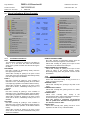
PUBLICATION: FIRECLASS Prescient III OMFCPRES3US ISSUE No. & DATE: 0 EQUIPMENT: WRITTEN BY: RKP CHECKED BY: AP 02/01/12 APPROVED BY: JBJ PRESCIENT III FIRE ALARM & GAS EXTINGUISHING CONTROL PANEL User Operation Manual PAGE 1 of 6 1 PUBLICATION: FIRECLASS Prescient III OMFCPRES3US ISSUE No. & DATE: 0 EQUIPMENT: WRITTEN BY: RKP CHECKED BY: AP 02/01/12 CONTENTS 1. 2. 3. 4. 5. 6. 7. FIRE - GENERAL................................................. 3 FIRE - ZONES 1 OR 2 - AUTOMATIC MODE ........... 3 FIRE - ZONES 1 OR 2 - MANUAL MODE ................ 3 AUTOMATIC OR MANUAL MODE - MANUAL RELEASE........................................................... 3 EMERGENCY ABORT .......................................... 3 FAULT INDICATION.............................................. 3 CIRCUIT DISABLEMENT ....................................... 3 8. DISPLAY TEST ................................................... 3 9. ROUTINE SYSTEM TEST ..................................... 3 10. VISUAL INDICATIONS & USER CONTROLS ............ 4 10.1 FIRE STATUS INDICATIONS ...................... 4 10.2 COMMON STATUS INDICATIONS ............... 4 10.3 EXTINGUISHING STATUS INDICATIONS ...... 5 10.4 USER CONTROLS .................................... 5 Danger This equipment contains hazardous voltages that can cause death, serious personal injury, or equipment damage. This equipment contains no user serviceable parts. Refer all maintenance to suitably qualified personnel. PAGE 2 of 6 PUBLICATION: FIRECLASS Prescient III OMFCPRES3US ISSUE No. & DATE: 0 EQUIPMENT: Fire - General The RED zonal fire LEDs will pulse, the alarms will sound and the internal buzzer will pulse once every second. Locate the source of the fire (an LED will be visible on the detector which has been activated). To silence the alarms, press SILENCE ALARMS. The alarms will silence and the red fire LEDs will change to a steady illumination. If necessary, the alarms can be reactivated by pressing RESOUND ALARMS. When the fire has been extinguished, press FIRE RESET. Should the system have activated for no apparent reason, please note which detector has been activated before pressing the FIRE RESET button; then contact your service engineer. 2. Fire - Zones 1 or 2 - Automatic Mode If a fire is detected on either zone 1 or zone 2, the relevant red zone LEDs will pulse, the alarms will sound and the System Activated LED will pulse. If a fire is detected on both zones 1 & 2, both zone LEDs will pulse, the alarms will sound and the System Activated LED will illuminate steady. In addition: the extinguishing Sounders will pulse and the Seconds to Discharge will show the Extinguishant Release Timer countdown. The Extinguishant Release Timer may be stopped manually by pressing the Timer Hold button on a Status Lamp Unit (the Timer will be reset to the start of the countdown). The extinguishing Sounders will change to a longer pulse period. When the button is released the timer will start running again and the extinguishing Sounders will return to the short pulse. When the Timer ends the Seconds To Discharge display will clear and the Extinguishant will be released. Once the extinguishant has been released the extinguishing sounders will change to a continuous operation. 3. CHECKED BY: AP 02/01/12 NOTE: Rotate the ACCESS CONTROLS key to the ON position in order to operate any of the USER CONTROLS. Remove the Key when the panel is to be left unattended. 1. WRITTEN BY: RKP Fire - Zones 1 or 2 - Manual Mode The system will behave as outlined for automatic mode with the exception that the System Activated LED will not be illuminated steady and the extinguishant release timer will not be initiated. In this case the Extinguishant can only be released by operation of manual release. 4. Automatic or Manual Mode - Manual Release If a Manual Release switch is operated, the Manual Release LEDs will pulse, the alarms will sound, and the Seconds to Discharge display will show the Extinguishant Release Timer countdown. The timer can be suspended as described above. The extinguishant will be released after timer ends. 5. Emergency Abort The Extinguishant Release may be aborted at any time by operating the Emergency Abort switch on a Status Lamp Unit. Once aborted, the system must be fully reset by sequential operation of the FIRE RESET & EXTINGUISHING SYSTEM RESET buttons. The latched Abort switch must also be returned to the OFF position. 6. Fault Indication The internal buzzer will pulse once every 3 seconds and the appropriate fault LED(s) will pulse. Call your service engineer immediately. Press SILENCE BUZZER to silence the buzzer. WARNING: This equipment contains dangerous voltages. To prevent electric shock, do not open the panel door. There are no user-serviceable parts inside - for servicing, contact suitably qualified personnel. 7. Circuit Disablement To disable a circuit, press the SELECT ON/OFF button. The SELECT cursor will flash on the FIRE SIGNAL fault LED. Press the SCROLL button to move the cursor to the required circuit fault LED and then press the DISABLE button. To enable a circuit, repeat the above procedure to select the required circuit and press the ENABLE button. Press the SELECT ON/OFF button to cancel the SELECT cursor. 8. Display Test The TEST button should be operated every week as part of the system test routine for checking correct operation of the panel buzzer and all LEDs. Press and release the button to sound the buzzer and illuminate all the LEDs for 5 seconds. 9. Routine System Test This should be carried out in accordance with the recommendations of the local Fire Prevention Officer. Refer to the Logbook. PAGE 3 of 6 PUBLICATION: FIRECLASS Prescient III OMFCPRES3US ISSUE No. & DATE: 0 EQUIPMENT: 10. WRITTEN BY: RKP CHECKED BY: AP 02/01/12 Visual Indications & User Controls FIRE STATUS USER CONTROLS AUTO & MANUAL FIRE FIRE SIGNAL SILENCE ALARMS RESOUND ALARMS ZONE 1 FIRE RESET REMOTE SOUND ALARMS EXTINGUISHING SYSTEM RESET (INHIBITED) REMOTE CONTROLS FAULT FIRE SOUNDER FAULT/DISABLED MANUAL ONLY MANUAL RELEASE ACTIVE SYSTEM ACTIVATED ZONE 2 AUX ZONE EXTINGUISHING STATUS GAS RELEASED GAS RELEASED SIGNAL ACTIVE EMERGENCY ABORT ACTIVE EMERGENCY HOLD ACTIVE SILENCE BUZZER AUTO & MAN/ MANUAL ONLY CIRCUIT FAULT GAS LOW COMMON STATUS GAS TRAPPED IN MANIFOLD POWER SUPPLY ON GENERAL FAULT SELECT ON/OFF ENABLE ISOLATION VALVE CLOSED POWER SUPPLY FAULT SYSTEM FAULT MANUAL RELEASE FAULT/DISABLED SCROLL DISABLE EARTH FAULT 10.1 ISOLATION VALVE ABNORMAL EXTINGUISHING DISABLED GAS RELEASED SIGNAL DISABLED SHUTDOWN OUTPUTS DISABLED FUSE FAILED OFF FAULT SIGNAL FAULT/DISABLED ACCESS CONTROLS SOUNDER TEST ON Fire Status Indications FIRE Two Red LEDs: normally off, pulsing for a fire alarm on zones 1, 2, or Aux Zone. The LEDs are illuminated steady if the general sounders are silenced during the fire alarm. FIRE SIGNAL Red LED: normally off, illuminating steady when the Fire Signal output is active. Yellow LED: normally off, pulsing for an open or short circuit fault on the Fire Signal output, illuminating steady if the Fire Signal output is disabled. ZONE 1 Red LED: normally off, pulsing if a fire condition is detected on zone 1, illuminating steady when the alarm is accepted (by operation of the Silence Alarms button). Yellow LED: normally off, pulsing for an open or short circuit fault on Zone 1, illuminating steady if Zone 1 is disabled. ZONE 2 Red LED: normally off, pulsing if a fire condition is detected on zone 2, illuminating steady when the alarm is accepted (by operation of the Silence Alarms button). Yellow LED: normally off, pulsing for an open or short circuit fault on Zone 2, illuminating steady if Zone 2 is disabled. AUX ZONE Red LED: normally off, pulsing if a fire condition is detected on the Aux Zone, illuminating steady when the alarm is accepted (by operation of the Silence Alarms button). Yellow LED: normally off, pulsing for an open or short circuit fault on the Aux Zone, illuminated steady if the Aux Zone is disabled. TEST SECONDS TO DISCHARGE REMOTE SOUND ALARMS Red LED: normally off, illuminating steady when the Remote Controls input registers a Sound Alarms. Yellow LED: normally off, pulsing for an open or short circuit fault on the Remote Controls input. FIRE SOUNDER FAULT/DISABLED Yellow LED: normally off, pulsing for an open or short circuit on either of the general sounder circuits, illuminating steady when the general sounder circuits are disabled. 10.2 Common Status Indications POWER SUPPLY ON Green LED: illuminated steady as long as there is a supply of power to the panel. GENERAL FAULT Yellow LED: normally OFF, pulsing for any fault on the panel. POWER SUPPLY FAULT Yellow LED: normally OFF, pulsing if there is a mains or battery failure. SYSTEM FAULT Yellow LED: normally OFF, steady if the microprocessor fails to execute the software correctly or an internal memory corruption is detected. Note: The system is completely non-functional when in system fault. Alternative arrangements for fire detection must be made. EARTH FAULT Yellow LED: normally OFF, pulsing if there is a low impedance to earth on any of the field cables. PAGE 4 of 6 PUBLICATION: FIRECLASS Prescient III OMFCPRES3US ISSUE No. & DATE: 0 EQUIPMENT: CHECKED BY: AP 02/01/12 FUSE FAILED Yellow LED: normally OFF, pulsing if either of the electronic fuses on the two auxiliary 24V supply outputs activate due to excessive loading. FAULT SIGNAL FAULT/DISABLED Yellow LED: normally off, pulsing for an open or short circuit fault on the Fault Signal output, illuminating steady if the Fault Signal output is disabled. SOUNDER TEST Yellow LED: normally off, illuminating steady when the three sounder circuits are in the TEST mode. 10.3 WRITTEN BY: RKP Extinguishing Status Indications AUTO & MANUAL Yellow LED: illuminated steady if the actuators can be operated both automatically (via a fire alarm on zones 1 & 2) and manually (via manual release). MANUAL ONLY Yellow LED: illuminated steady if the actuators can only be operated manually (via manual release), pulsing if an AUTO/MANUAL switch in the field is set to Manual MANUAL RELEASE ACTIVE Red LED: normally off, pulsing if manual release is activated, illuminating steady when the alarm is accepted (by operation of the Silence Alarms button when not inhibited). SYSTEM ACTIVATED Red LED: normally OFF, pulsing during the preactivated condition, illuminating steady during the activated condition. GAS RELEASED Red LED: normally OFF, illuminating steady when the extinguishing gas is released. GAS RELEASED SIGNAL ACTIVE Red LED: normally off, illuminating steady when the Gas Released output is active. EMERGENCY ABORT ACTIVE Yellow LED: normally OFF, pulsing if a fault occurs on the Abort input while the Extinguishing System is not in the pre-activated or activated state, illuminating steady if the emergency Abort switch on a Status Lamp Unit is activated, or a fault occurs on the input during the preactivated or activated state. EMERGENCY HOLD ACTIVE Yellow LED: normally OFF, pulsing if the Hold button on a Status Lamp Unit is pressed when the pre-discharge delay timer is not running, illuminating steady If the Hold button is pressed or a fault occurs on the input while the pre-discharge delay timer is running. CIRCUIT FAULT Yellow LED: normally OFF, pulsing when any of the circuits related to the Extinguishing system has a fault. GAS LOW Yellow LED: normally OFF, pulsing when the quantity of extinguishing gas in the bottles is too low. GAS TRAPPED IN MANIFOLD Yellow LED: normally OFF, pulsing when the gas fails to exit from the manifold. ISOLATION VALVE ABNORMAL Yellow LED: normally OFF, pulsing when the Isolation valve is stuck between open & closed positions. ISOLATION VALVE CLOSED Yellow LED: normally OFF, pulsing when the Isolation Valve is fully closed. MANUAL RELEASE FAULT/DISABLED Yellow LED: normally OFF, pulsing if the Manual Release zone input is in fault or the internal circuit to the door mounted Manual Release is in fault, illuminating steady when the Manual Release facility is disabled. EXTINGUISHING DISABLED Yellow LED: normally OFF, illuminating steady when the extinguishing gas release facility is disabled. GAS RELEASED SIGNAL DISABLED Yellow LED: normally OFF, illuminating steady when the Gas Released Signal output is disabled. SHUTDOWN OUTPUTS DISABLED Yellow LED: normally OFF, illuminating steady when st nd rd the 1 Stage, 2 Stage & 3 Stage shutdown outputs are disabled. SECONDS TO DISCHARGE Red 2-digit numeric display: normally off. When the predischarge timer is running, the remaining seconds left to discharge are shown. 10.4 User Controls All buttons except for TEST (for Test Display) are disabled until the ACCESS CONTROLS key-switch is rotated to the ON position. SILENCE ALARMS Silences the general sounders and/or the extinguishing sounders (unless inhibited). Yellow LED: normally OFF, pulsing when it is possible to silence any of the sounder circuits, illuminating steady when sounder circuits have been silenced. RESOUND ALARMS Causes previously silenced sounders to be resounded. FIRE RESET Resets fault and fire indications on the Fire Alarm section of the panel. Faults common to the Fire section & the Extinguishing section are also reset. EXTINGUISHING RESET When not inhibited, resets fault and active indications on the Extinguishing section of the panel. Faults common to the Fire section & the Extinguishing section are also reset. Yellow LED: normally off, illuminating steady when the Extinguishing System Reset is inhibited. SILENCE BUZZER Silences the internal buzzer during any fault or alarm condition. Yellow LED: normally off, illuminating steady when the buzzer has been silenced. AUTO & MANUAL / MANUAL ONLY Toggles the panel status between Automatic & Manual and Manual Only modes. SELECT ON/OFF Toggles the Circuit Select Cursor ON and OFF. ENABLE Valid only while the Circuit Select Cursor is ON. Restores the selected circuit to normal operation (cancels test & disabled states). DISABLE PAGE 5 of 6 PUBLICATION: FIRECLASS Prescient III OMFCPRES3US ISSUE No. & DATE: 0 EQUIPMENT: WRITTEN BY: RKP CHECKED BY: AP 02/01/12 Valid only while the Circuit Select Cursor is ON. Disables the selected circuit. TEST Circuit Select Cursor OFF: Operates the Test Display feature, sounding the internal buzzer and illuminating all the LEDs on the Display for five seconds. Circuit Select Cursor ON: Places the selected circuit into test mode. SCROLL Valid only while the Circuit Select Cursor is ON. Moves the Circuit Select cursor through the available circuit LEDs. Note: All zone disable/enable operations result in the zone power supply being disconnected for 10 seconds. PAGE 6 of 6