1
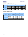
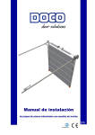
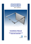
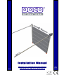
Installation Manual ‘Ready To Fit’ Overhead Sectional Doors Standard Lift, High Lift, Vertical Lift. UK Installation manual Contents 1 Symbols and/or warning signs 4 2 General 2.1 Safety requirements regarding installation and use 4 4 3 Directives and standards 3.1 Warranty and liability 5 5 4 Mounting 4.1 Application 4.1.1 Specifications 4.2 Scope of supply 4.3 Installation tools and accessories 4.4 Systems and system drawings 4.4.1 System drawing : Standard lift 4.4.2 System drawing : Standard Lift Pitched Tracks 4.4.3 System drawing : High Lift 4.4.4 System drawing : High Lift Pitched Tracks 4.4.5 System drawing : Vertical Lift 4.5 Installation details 4.6 General installation of vertical track sets 4.6.1 Standard lift 4.6.2 Standard lift pitched tracks 4.6.3 High lift 4.6.4 High Lift pitched tracks 4.6.5 Vertical lift (FL) 4.7 Connections between guide tracks and vertical angles 4.8 Drop down of the horizontal track set section 4.8.1 Track hangar requirements 4.9 Spring buffers 4.10 Spring set (power unit) 4.10.1 Configurations 4.10.2 Side bearing plates 4.10.3 Shafts 4.10.4 Keys 4.10.5 Spring break protection 25449 4.10.6 Centre/support consoles 4.10.7 Coupling 4.10.8 Torsion springs 4.10.9 Cable drums 4.10.10 Spring set installation (power unit) 4.11 Panels (general) 4.11.1 Hardware 4.11.2 Panel assembly 4.11.3 Intermediate sections 4.11.4 Positioning the bottom panel and intermediate sections 4.11.5 Positioning the top panel 4.12 Fitting the cable and positioning the cable drum 4.13 Tensioning the spring set 4.14 Correcting spring tension 4.15 Operation 4.15.1 Rope operation / manual operation 4.15.2 Chain operation ( 1:4 ) item 25025 4.15.3 Electric drive (slip-on motor) and control 4.15.3 a Control : Pulse control 4.15.3 b Control : Dead man control 4.15.3 c Control : Automatic or remote control 5 5 5 6 7 7 8,9 9,10 11 11 12,13 14 14 15 15 17 18 19 19 20 20 22 23 23 24 24 24 25 25 25 27 28 29 29 30 31 32 32 33 33 35 35 36 36 36,37 38 38 38 38,39 UK V1.1 2 Installation manual 4.16 Options 4.16.1 4.16.2 4.16.2.1 4.16.3 40 40 41 41 43 Windows Locks and bolts Lock 25226 / 25228 Handles 5 Commissioning 43 6 Troubleshooting 44 7 Dismantling 7.1 Disposal 45 45 8 Appendices Appendix 1 Appendix 2 Appendix 5 UK V1.1 Fixing vertical track sets Hardware / panels EN 13241-1 classification 46 46 47 3 Installation manual 1. Symbols and/or warning signs. General DANGER !! symbol ATTENTION !! symbol Carefully read the text when you see this symbol !! Symbol : Risk of personal injury!! Carefully read the text when you see this symbol !! 2. General This Installation Manual was written specifically for use by qualified personnel and is therefore not suitable for apprentices or 'DIY-ers'. If anything regarding installation and/or maintenance is not clear, please contact DOCO International. To prevent serious personal injury, all directions and instructions in this manual should be carefully read and observed. - This manual describes the installation of ‘Ready To Fit’ Overhead Doors with torsion springs, but it may be necessary to consult other installation manuals such as the one for the motor (if fitted). This ‘Ready To Fit’ Overhead Door is designed in accordance with the latest European standards, however you should check whether it complies with your local national standards. Adding or removing parts may have an adverse effect on the operation and thus the safety of the final sectional gate. All instructions regarding handing (right/left installation) are seen from the place of installation, i.e. from the inside looking out! Unless stated otherwise, all measurements are in millimetres. After installation, check whether the CE mark has been affixed and completed. This manual should be carefully stored. We reserve the right to modify specifications without written notice. 2.1 Safety requirements regarding installation and use - The ‘Ready To Fit’ Overhead Door may only be installed, connected and commisioned by skilled personnel. When working on the electrics, always ensure the power is and remains isolated! Never bypass safety features! Some parts have sharp edges - use safety gloves. Never operate the sectional gate if you see that the safety features are damaged. During installation / maintenance of the door, wear at least gloves, safety shoes and, when drilling, safety goggles! Always ensure a stable footing when working. Secure the installation / maintenance area using appropriate safety devices to keep others at a distance. Maintenance should only be performed by a specialist firm and/or qualified personnel. Provide adequate lighting. Only use suitable tools, especially for tensioning torsion springs. UK V1.1 4 Installation manual 3. Directives and standards The following directives and standards were used during the design, production and installation of these tracks. 98/37/EEC 89/106/EEC 89/336/EEC 73/23/EEC EN 12604:2000 EN 12605:2000 EN 12445:2000 EN 12453:2000 EN 13241-1:2003 Machine Directive Construction Equipment Directive EMC Directive Low Voltage Directive Mechanical aspects; requirements and classification Mechanical aspects; testing methods Safety for powered gates; testing methods Safety for powered gates, requirements Door and gate product standard 3.1 Warranty and liability Unprofessional installation, unauthorized alterations (other parts) to the door or alterations to the drive that are not in compliance with this manual will invalidate the warranty and thus will release the manufacturers from any liability. This also includes damage resulting from incorrect operation, failure to follow the instructions in this manual and/or poor maintenance and/or care. 4 Installation 4.1 Application DOCO International have developed ‘Ready To Fit’ Doors designed for installation in industrial entrances/exits to be used safely for vehicles and/or people.* These doors contain the following features: - Steel hardware sets with front torsion springs, fully balanced. - Compliance with the CE standard provided only DOCO International parts are used (unless stated otherwise). * If the gate is switched to automatic or remote control, extra measures need to be taken to guarantee safety! See paragraph 4.16.3.c) Control: Automatic operation or via remote. 4.1.1 Specifications Standard lift: 7.0m max. width 6.0m max. height Door surface: 36m2 max. Weight: 600kg max. Installation area: see system drawings High lift: 7.0m max. width 6.0m max. height High lift: 4.1m max. Door surface: 36m2 max. Weight: 600kg max. Installation area: see system drawings Vertical fitting: 7.0m max. width 6.0m max. height Door surface: 36m2 max. Weight: 600kg max. Installation area: see system drawings EN 13241-1 classification: see appendix 5 This manual describes the installation of a sectional door using only DOCO International parts. Any installation of parts not specified or other parts not described in this manual is the responsibility of the installer. The installer is therefore, responsible for the correct CE certification of the sectional door. UK V1.1 5 Installation manual DOCO International Limited has had the “product testing” of these doors carried out by the British Research Establishment in Watford, United Kingdom, registered as Notified Body No. 1576 and the TUV North in Germany, registered as Notified Body No 0032. This “product testing” does NOT include any wicket door. If you DO install a wicket door, additional “product testing” is needed. This is the responsibility of the purchaser/installer. 4.2 Scope of supply The door supplied by us includes the following parts, the details of which depend on the door dimensions and the type of lifting system. Track set: Vertical track set assembled Horizontal track set assembled Side seals Counterbalance assembly: - End bearing plates - Shaft - Cable drums - Steel cables - Spring break protection devices - Coupling - Assembled torsion springs - calculated for each individual door by our computer programme Hardware and panel related products: - Insulated door panels Cable break protection (base console) Side hinges Centre hinges End covers Stiffening profiles Rollers Aluminium bottom profile Aluminium top profile Bottom seal Top seal Spring bumpers Self-tapping screws Back track hangars and track bracing bar - dependant on width Options: - Lock - Handle - Chain hoist Drive and control unit: - Guthrie Douglas (GFA) Link Controls Kaba Garog Safety Bottom Edge : - Fraba set - Fraba end stop set UK V1.1 6 Installation manual 4.3 Installation tools Here is a minimum list of the necessary tools: - Level (hose) - Drill - Battery - drill - Jigsaw - Tensioning bars - Flexible steel rule - Ratchet and cover 10mm / 13mm - Ring/open-ended spanner: 10 – 11mm / 12 – 13mm - Gripper: 2x - Blind rivet pliers - Rope - Ladder or scaffolding / cherry picker / scissor lift - Iron file - Allen keys - Drill bits: Ø9 , Ø10 - Working gloves - Safety goggles - Safety boots Always wear safety goggles and gloves when drilling! Use stable and safe ladders or scaffolding! 4.4 Systems and system drawings We use the following 5 systems (lifts): - Standard system - Standard roof line system - High system - High roof line system - Vertical system ST ST pitch HL HL pitch VL The following pages feature system drawings for the systems mentioned. UK V1.1 7 see 4.4.1 see 4.4.2 see 4.4.3 see 4.4.4 see 4.4.5 Installation manual 4.4.1 System drawing: Standard lift < 3600mm high O veral l Track P rojectio n Bracing bar bolted to tracks using bolts/cleats provided = 250 min 1 25 m m = 100 wide x 150 deep plate required for e 50 x 50 x 1000mm (maximum) long dexion hangars 0 - 300 kg use 4 braced track hangars ( 2 per track) C le ar Openin g Heig ht Inside Plain Side Drive Side Push Up Doors 150 mm 150 mm Chain Operated Doors 150 mm 250 mm Electrically Operated Doors 150 mm 400 mm 1 52 mi n 75 mi n 301 - 450 kg use 6 braced track hangars (3 per track) 451 - 600 kg use 8 braced track hangars (4 per track) Sideroom Details electrically operated doors (fit RH or LH as required). 1 65 k S lo p 42 0 Headroom eT ra c Notes 1. All internal faces must be flush and free from projections. 75 m i n For reduced sideroom requirements contact our technical department 2. The opening structure must be capable of withstanding all loads imposed by the door and fixings - approx weight C le ar Openi ng Heig ht 42 0 Headroom De gre Above cle ar opghei ght Clear zone for door 75 mi n 25kg/m2. 3. Electrically operated doors require a 3 phase, 400 volt, Important Note - 50hz with neutral, 10 amp per phase supply. Isolators Track hangars should be no longer than 1000mm. It is the installation company's responsibility to ensure the adequacy of the support terminating with a 3 phase CEE socket within 0.5 metre of the control panel and 0.9 to 1.7 metres above FFL. framework and design for hangars in excess of 1000mm. Floor to be laid to fall away from door to prevent water ingress at threshold. FFL Vertical Section Steelwork Elevation (from Inside) Note: 100mm sideroom required For openings 6000 wide or above, 75mm Quantity of doors: Panel finish: at jamb for clear door wide jambs to be increased to 125 mm. Specification Operation: Plastisol or Stucco Polyester - Colour Push Up / Chain Operated / 3ph Electric Opertion Handing: Vision panels: RH / LH viewed from inside 85600 row of in panels Wicket door: Centrally located with cylinder lock, lever handles and closer Cable Break Device: Spring Break Device: Yes / No height for cable break device clearance Li neof li ntol over Electric Interlock Switch Inside 75 mi n Yes/No Locking: Yes / No Electric Interlock Switch Yes/No Spring loaded shootbolt Electric Interlock Switch Footstep Handle: Manual doors only - fitted RH/IS unless shown differently above Yes/No Unit K4 The Metropolitan Centre Field Way, Greenford, 75 mi n C le ar Openin g W idth Sid eroom as table S ideroom as tabl e Sectional Plan Title Ready To Fit Sectional Overhead Door - Standard Lift - For Openings Up To 3600mm High Middlesex UB6 8UN T: 020 8813 2266 F: 020 8813 2288 E: [email protected] Customer Date Drawn By Site Drawing No Revision Standard Drawing No 10003/v1.0 4.4.1 System drawing: Standard lift >3600 < 5100mm high Ov erall Track Proj ecti on 0 - 300 kg use 4 braced track hangars ( 2 per track) 301 - 450 kg use 6 braced track hangars (3 per track) 451 - 600 kg use 8 braced track hangars (4 per track) 1 52 mi n 2 40 2 degreesl ope 50 x 50 x 1000mm (maximum) long dexion hangars Notes Bracing bar bolted to tracks using bolts/cleats provided Sideroom Details Plain Side Drive Side Push Up Doors 150 mm 150 mm C le ar Openin g Heig ht Chain Operated Doors Electrically Operated Doors 150 mm 250 mm 150 mm 400 mm 5 0 0 Headroom electrically operated doors (fit RH or LH as required). 75 mi n 50 0 Headroom Clear zone for door 100 wide x 150 deep plate required for 1. All internal faces must be flush and free from projections. 2. The opening structure must be capable of withstanding all loads imposed by the door and fixings - approx weight 25kg/m2. 3. Electrically operated doors require a 3 phase, 400 volt, 50hz with neutral, 10 amp per phase supply. Isolators terminating with a 3 phase CEE socket within 0.5 metre of the control panel and 0.9 to 1.7 metres above FFL. C le ar Openin g Heig ht 500 min 10 0 m m = Above cl earopg heig ht = For reduced sideroom requirements contact our technical department Inside 75 m i n 75 mi n Important Note Track hangars should be no longer than 1000mm. It is the installation company's responsibility to ensure the adequacy of the support framework and design for hangars in excess of 1000mm. Floor to be laid to fall away from door to prevent water ingress at threshold. FFL Vertical Section Steelwork Elevation (from Inside) Note: For openings 6000 wide or above, 75mm Specification 100mm sideroom required at jamb for clear door height for cable break wide jambs to be increased to 125 mm. Quantity of doors: Panel finish: Operation: Handing: device clearance Plastisol or Stucco Polyester - Colour Push Up / Chain Operated / 3ph Electric Opertion Vision panels: RH / LH viewed from inside 85600 row of in panels Wicket door: Cable Break Device: Centrally located with cylinder lock, lever handles and closer Yes / No Electric Interlock Switch Yes/No Spring Break Device: Yes / No Locking: Footstep Handle: Electric Interlock Switch Spring loaded shootbolt Li neof li ntol over Inside 75 mi n Yes/No Electric Interlock Switch 75 mi n C le ar Openin g W idth Sid eroom as table Yes/No S ideroom as tabl e Manual doors only - fitted RH/IS unless shown differently above Sectional Plan Unit K4 The Metropolitan Centre Field Way, Greenford, Middlesex UB6 8UN T: 020 8813 2266 F: 020 8813 2288 E: [email protected] Title Ready To Fit Sectional Overhead Door - Standard Lift - For Openings Between 3601 and 5100 high Customer Date Drawn By Site Drawing No Revision Standard Drawing No 10001/v1.0 UK V1.1 8 Installation manual 4.4.1 System drawing: Standard lift >5100mm high Ov erall Track Proj ecti on electrically operated doors (fit RH or LH as required). 20 3 m i n 6 00 Headroom Clear zone for door 100 wide x 150 deep plate required for 2 degreesl ope 50 x 50 x 1000mm (maximum) long dexion hangars 0 - 300 kg use 4 braced track hangars ( 2 per track) 301 - 450 kg use 6 braced track hangars (3 per track) 24 0 750 min 75min 451 - 600 kg use 8 braced track hangars (4 per track) Notes 1. All internal faces must be flush and free from projections. Bracing bar bolted to tracks using bolts/cleats provided 6 00 Headroom = 10 0 m m = Above cle ar opg hei ght = Plain Side Push Up Doors 150 mm 150 mm Chain Operated Doors 150 mm 250 mm Electrically Operated Doors 150 mm 400 mm all loads imposed by the door and fixings - approx weight 25kg/m2. 3. Electrically operated doors require a 3 phase, 400 volt, 50hz with neutral, 10 amp per phase supply. Isolators terminating with a 3 phase CEE socket within 0.5 metre of the control panel and 0.9 to 1.7 metres above FFL. Cl earO penin g Hei ght Cl earO penin g Hei ght 2. The opening structure must be capable of withstanding Sideroom Details Drive Side For reduced sideroom requirements contact our technical department Inside 75 m i n 75 mi n Important Note Track hangars should be no longer than 1000mm. It is the installation company's responsibility to ensure the adequacy of the support framework and design for hangars in excess of 1000mm. Floor to be laid to fall away from door to prevent water ingress at threshold. FFL Vertical Section Steelwork Elevation (from Inside) Note: 100mm sideroom required at jamb for clear door For openings 6000 wide or above, 75mm wide jambs to be increased to 125 mm. Specification height for cable break Quantity of doors: Panel finish: Operation: Handing: device clearance Plastisol or Stucco Polyester - Colour Push Up / Chain Operated / 3ph Electric Opertion RH / LH viewed from inside Li neof li ntol over Vision panels: Wicket door: 85600 row of in panels Centrally located with cylinder lock, lever handles and closer Cable Break Device: Yes / No Spring Break Device: Locking: Yes / No Electric Interlock Switch Yes/No Spring loaded shootbolt Electric Interlock Switch Footstep Handle: Manual doors only - fitted RH/IS unless shown differently above Electric Interlock Switch Inside 75 mi n Yes/No Unit K4 The Metropolitan Centre Field Way, Greenford, 75 mi n C le ar Openin g W idth Sid eroom as table Yes/No S ideroom as tabl e Sectional Plan Title Ready To Fit Sectional Overhead Door - Standard Lift - For Openings Above 5101 High Middlesex UB6 8UN T: 020 8813 2266 F: 020 8813 2288 E: [email protected] Customer Date Drawn By Site Drawing No Revision Standard Drawing No 10002/v1.0 4.4.2 System drawing: Standard lift < 3600mm high with pitched back tracks O veral l Track P roje ctio n Bracing bar bolted to tracks using bolts/cleats provided = 250 min 1 25 mm = 100 wide x 150 deep plate required for electrically operated doors (fit RH or LH 0 - 300 kg use 4 braced track hangars ( 2 per track) 301 - 450 kg use 6 braced track hangars (3 per track) C le ar Openin g Heig ht Inside Plain Side Drive Side Push Up Doors 150 mm 150 mm Chain Operated Doors 150 mm 250 mm Electrically Operated Doors 150 mm 400 mm 1 52 mi n 75 mi n 451 - 600 kg use 8 braced track hangars (4 per track) 165 50 x 50 x 1000mm (maximum) long dexion hangars Sideroom Details as required). 42 0 Headroom lo p e Notes 75 m i n For reduced sideroom requirements contact our technical department 1. All internal faces must be flush and free from projections. 2. The opening structure must be capable of withstanding Cl ear Op eni ng Hei ght 42 0 Headroom Degr ck S ee T ra Above cl ear opg hei ght Clear zone for door 75 mi n all loads imposed by the door and fixings - approx weight 25kg/m2. 3. Electrically operated doors require a 3 phase, 400 volt, Important Note Track hangars should be no longer than 1000mm. It is the installation 50hz with neutral, 10 amp per phase supply. Isolators terminating with a 3 phase CEE socket within 0.5 metre of the control panel and 0.9 to 1.7 metres above FFL. company's responsibility to ensure the adequacy of the support framework and design for hangars in excess of 1000mm. Floor to be laid to fall away from door to prevent water ingress at threshold. FFL Vertical Section Steelwork Elevation (from Inside) Note: 100mm sideroom required For openings 6000 wide or above, 75mm Quantity of doors: Panel finish: at jamb for clear door height for cable break wide jambs to be increased to 125 mm. Specification device clearance Operation: Plastisol or Stucco Polyester - Colour Push Up / Chain Operated / 3ph Electric Opertion Handing: Vision panels: RH / LH viewed from inside 85600 row of in panels Wicket door: Cable Break Device: Centrally located with cylinder lock, lever handles and closer Yes / No Electric Interlock Switch Yes/No Spring Break Device: Locking: Yes / No Electric Interlock Switch Yes/No Spring loaded shootbolt Electric Interlock Switch Footstep Handle: Manual doors only - fitted RH/IS unless shown differently above Unit K4 The Metropolitan Centre Field Way, Greenford, Middlesex UB6 8UN T: 020 8813 2266 F: 020 8813 2288 E: [email protected] Li neof li ntol over Inside 75 mi n 75 mi n C le ar Openin g W idth Sid eroom as table S ideroom as tabl e Yes/No Sectional Plan Title Ready To Fit Sectional Overhead Door - Standard Lift - For Openings Up To 3600mm High Customer Date Drawn By Site Drawing No Revision Standard Drawing No 10003/v1.0 UK V1.1 9 Installation manual 4.4.2 System drawing: Standard lift >3600 < 5100mm high with pitched back tracks = 250 min 100 wide x 150 deep plate required for electrically operated doors (fit RH or LH 0 - 300 kg use 4 braced track hangars ( 2 per track) 301 - 450 kg use 6 braced track hangars (3 per track) C le ar Open in g Heig h t Plain Side Drive Side Push Up Doors 150 mm 150 mm Chain Operated Doors 150 mm 250 mm Electrically Operated Doors 150 mm 400 mm 1 5 2 m in 7 5 m in 451 - 600 kg use 8 braced track hangars (4 per track) 24 0 50 x 50 x 1000mm (maximum) long dexion hangars Sideroom Details as required). 5 00 Headroom Sl ope Notes Inside 75 mi n For reduced sideroom requirements contact our technical department 1. All internal faces must be flush and free from projections. 2. The opening structure must be capable of withstanding Cl earO peni n gHei ght ck ree Tra Deg Abov ecl earopg heig ht Clear zone for door 5 00 Headro om 125mm Bracing bar bolted to tracks using bolts/cleats provided O veral l Track P roj ectio n = 75 mi n all loads imposed by the door and fixings - approx weight 25kg/m2. 3. Electrically operated doors require a 3 phase, 400 volt, Important Note Track hangars should be no longer than 1000mm. It is the installation 50hz with neutral, 10 amp per phase supply. Isolators terminating with a 3 phase CEE socket within 0.5 metre of company's responsibility to ensure the adequacy of the support framework and design for hangars in excess of 1000mm. the control panel and 0.9 to 1.7 metres above FFL. Floor to be laid to fall away from door to prevent water ingress at threshold. FFL Vertical Section Quantity of doors: Panel finish: Operation: Handing: Vision panels: Wicket door: Cable Break Device: Spring Break Device: Locking: Footstep Handle: Steelwork Elevation (from Inside) Note: 100mm sideroom required For openings 6000 wide or above, 75mm wide jambs to be increased to 125 mm. Specification at jamb for clear door height for cable break device clearance Plastisol or Stucco Polyester - Colour Push Up / Chain Operated / 3ph Electric Opertion RH / LH viewed from inside 85600 row of in panels Lin e ofl i ntol ov er Centrally located with cylinder lock, lever handles and closer Yes / No Electric Interlock Switch Yes/No Yes / No Electric Interlock Switch Yes/No Spring loaded shootbolt Electric Interlock Switch Inside 75 mi n 75 mi n Cl earO peni n gW i dth Si deroom as table Yes/No S i deroom as tabl e Manual doors only - fitted RH/IS unless shown differently above Sectional Plan Unit K4 The Metropolitan Centre Field Way, Greenford, Title Ready To Fit Sectional Overhead Door - Standard Lift - For Openings Between 3601 and 5100 High Middlesex UB6 8UN T: 020 8813 2266 F: 020 8813 2288 E: [email protected] Customer Date Drawn By Site Drawing No Revision Standard Drawing No 10004/v1.0 4.4.2 System drawing: Standard lift >5100mm high with pitched back tracks O veral l Track P roje ctio n = 250 min 1 25 mm = 100 wide x 150 deep plate required for electrically operated doors (fit RH or LH 50 x 50 x 1000mm (maximum) long dexion hangars Inside Drive Side 150 mm 150 mm Chain Operated Doors 150 mm 250 mm Electrically Operated Doors 150 mm 400 mm 75 mi n Plain Side Push Up Doors Notes 1. All internal faces must be flush and free from projections. 75 m i n For reduced sideroom requirements contact our technical department 2. The opening structure must be capable of withstanding Cl ear O peni ng Hei ght C le ar Openi ng Heig ht 0 - 300 kg use 4 braced track hangars ( 2 per track) Sideroom Details as required). 50 0 Headroom lo p e 1 52 m in T ra c k S 240 5 00 H eadroom ee Degr Above cl ear opg hei ght Clear zone for door 75 mi n all loads imposed by the door and fixings - approx weight 25kg/m2. 3. Electrically operated doors require a 3 phase, 400 volt, Important Note - 50hz with neutral, 10 amp per phase supply. Isolators terminating with a 3 phase CEE socket within 0.5 metre of Track hangars should be no longer than 1000mm. It is the installation company's responsibility to ensure the adequacy of the support the control panel and 0.9 to 1.7 metres above FFL. framework and design for hangars in excess of 1000mm. Floor to be laid to fall away from door to prevent water ingress at threshold. FFL Vertical Section Steelwork Elevation (from Inside) Note: 100mm sideroom required at jamb for clear door For openings 6000 wide or above, 75mm Specification wide jambs to be increased to 125 mm. height for cable break Quantity of doors: Panel finish: Operation: device clearance Plastisol or Stucco Polyester - Colour Push Up / Chain Operated / 3ph Electric Opertion Handing: RH / LH viewed from inside Vision panels: Wicket door: 85600 row of in panels Centrally located with cylinder lock, lever handles and closer Yes / No Electric Interlock Switch Yes/No Cable Break Device: Spring Break Device: Locking: Footstep Handle: Yes / No Electric Interlock Switch Spring loaded shootbolt Electric Interlock Switch Manual doors only - fitted RH/IS unless shown differently above E: [email protected] 75 mi n C le ar Openin g W idth Sid eroom as table Yes/No Unit K4 The Metropolitan Centre Field Way, Greenford, Middlesex UB6 8UN T: 020 8813 2266 F: 020 8813 2288 UK V1.1 Li neof li ntol over Inside 75 mi n Yes/No S ideroom as tabl e Sectional Plan Title Ready To Fit Sectional Overhead Door - Standard Lift - For Openings Between 3601 and 5100 High 10 Customer Date Drawn By Site Drawing No Revision Installation manual 4.4.3 System drawing: High lift O verall Track P ro j ectio n (TP )= OH - HL + 70 0 250 min electrically operated doors (fit RH or LH as required). Sideroom Details Plain Side Drive Side Push Up Doors 150 mm 150 mm 150 mm 250 mm 150 mm 400 mm Chain Operated Doors Cl earO peni ngHei ght (O H) Electrically Operated Doors Inside 7 5 m in Bracing bar bolted to tracks using bolts/cleats provided 75 m i n For reduced sideroom requirements contact our technical department Cl earO peni ngHei ght Hig h Li ft( HL ) 451 - 600 kg use 8 braced track hangars (4 per track) Headroom Abov ecl earopg heig ht Headroom 0 - 300 kg use 4 braced track hangars ( 2 per track) 301 - 450 kg use 6 braced track hangars (3 per track) (TP x 0.0 4) + OH + HL 2 degre e sl ope 50 x 50 x 1000mm (maximum) long dexion hangars B etweenS teels 20 3 Clear zone for door 100 wide x 150 deep plate required for 1 40 = 12 5 m m = 75 mi n Notes 1. All internal faces must be flush and free from projections. 2. The opening structure must be capable of withstanding Important Note Track hangars should be no longer than 1000mm. It is the installation all loads imposed by the door and fixings - approx weight 25kg/m2. company's responsibility to ensure the adequacy of the support framework and design for hangars in excess of 1000mm. 3. Electrically operated doors require a 3 phase, 400 volt, 50hz with neutral, 10 amp per phase supply. Isolators terminating with a 3 phase CEE socket within 0.5 metre of Floor to be laid to fall away from door the control panel and 0.9 to 1.7 metres above FFL. to prevent water ingress at threshold. FFL Steelwork Elevation (from Inside) Note: Vertical Section For openings 6000 wide or above, 75mm 100mm sideroom required wide jambs to be increased to 125 mm. Specification at jamb for clear door height for cable break device clearance Quantity of doors: Panel finish: Operation: Plastisol or Stucco Polyester - Colour Push Up / Chain Operated / 3ph Electric Opertion Handing: Vision panels: RH / LH viewed from inside Wicket door: Cable Break Device: Spring Break Device: Locking: Footstep Handle: L in e ofl in tol ov er 85600 row of in panels Centrally located with cylinder lock, lever handles and closer Yes / No Electric Interlock Switch Yes/No Yes / No Electric Interlock Switch Inside 75 mi n 7 5 m in fix in g face Si deroom astabl e Yes/No Spring loaded shootbolt Electric Interlock Switch Yes/No Manual doors only - fitted RH/IS unless shown differently above Unit K4 The Metropolitan Centre Field Way, Greenford, Middlesex UB6 8UN T: 020 8813 2266 F: 020 8813 2288 Cl ear O peni ngW i dth Si deroom as table Sectional Plan Title Ready To Fit Sectional Overhead Door - High Lift Customer Date Site Drawing No Drawn By Revision E: [email protected] Standard Drawing No 10006/v1.0 4.4.4 System drawing: High lift with pitched back tracks = 250 min 1 25 mm Ov erall Track Proj ecti on (T P) = OH - HL + 7 00 = 100 wide x 150 deep plate required for 14 0 Inside Plain Side Drive Side Push Up Doors 150 mm 150 mm Chain Operated Doors 150 mm 250 mm Electrically Operated Doors 150 mm 400 mm 75 mi n Bracing bar bolted to tracks using bolts/cleats provided Sideroom Details Headroom 203 (T P x 451 - 600 kg use 8 braced track hangars (4 per track) 7 5 m in For reduced sideroom requirements contact our technical department Cle ar Open i ng Heig h t Hig h Li ft 0 - 300 kg use 4 braced track hangars ( 2 per track) 301 - 450 kg use 6 braced track hangars (3 per track) Between Steels k Sl ope ) +O H +HL eTr ac 50 x 50 x 1000mm (maximum) long dexion hangars Cl earO pen in g Hei gh t(O H) Headroom De gre Above cle ar opghei ght electrically operated doors (fit RH or LH as required). Clear zone for door 7 5 m in Notes 1. All internal faces must be flush and free from projections. Important Note - 2. The opening structure must be capable of withstanding all loads imposed by the door and fixings - approx weight Track hangars should be no longer than 1000mm. It is the installation company's responsibility to ensure the adequacy of the support framework and design for hangars in excess of 1000mm. 25kg/m2. 3. Electrically operated doors require a 3 phase, 400 volt, 50hz with neutral, 10 amp per phase supply. Isolators terminating with a 3 phase CEE socket within 0.5 metre of Floor to be laid to fall away from door to prevent water ingress at threshold. the control panel and 0.9 to 1.7 metres above FFL. FFL Vertical Section Steelwork Elevation (from Inside) Note: For openings 6000 wide or above, 75mm Specification 100mm sideroom required at jamb for clear door wide jambs to be increased to 125 mm. height for cable break Quantity of doors: Panel finish: Operation: Handing: device clearance Plastisol or Stucco Polyester - Colour Push Up / Chain Operated / 3ph Electric Opertion RH / LH viewed from inside Vision panels: Wicket door: 85600 row of in panels Centrally located with cylinder lock, lever handles and closer Cable Break Device: Yes / No Spring Break Device: Yes / No Electric Interlock Switch Yes/No Spring loaded shootbolt Electric Interlock Switch Locking: Footstep Handle: Electric Interlock Switch L in e ofl in tol ov er Inside Yes/No 7 5 m in Manual doors only - fitted RH/IS unless shown differently above Unit K4 The Metropolitan Centre Field Way, Greenford, Middlesex UB6 8UN T: 020 8813 2266 F: 020 8813 2288 E: [email protected] 7 5 m in fix in g face S ideroom as table Yes/No Cl ear O pen i n gW i dt h Si dero om as table Sectional Plan Title Ready To Fit Sectional Overhead Door - High Lift With Pitched Tracks Customer Date Drawn By Site Drawing No Revision Standard Drawing No 10007/v1.0 UK V1.1 11 Installation manual 4.4.5 System drawing: Vertical lif t < 3350mm 100 wide x 150 deep plate required for 2 03 150 mm Chain Operated Doors 150 mm 250 mm Electrically Operated Doors 150 mm 400 mm For reduced sideroom requirements contact our technical department Cl ear Openi ng Hei ght (O H) Headroom Between Steels Drive Side 150 mm (Openin g Heig ht + 18 0m m) Plain Side Push Up Doors 75min Sideroom Details Inside 75 m i n Cl earO penin g Heig ht ToU/ S Spri ng B eam Headroom 20 3 1 40 electrically operated doors (fit RH or LH as required). 75 mi n Notes 1. All internal faces must be flush and free from projections. 2. The opening structure must be capable of withstanding all loads imposed by the door and fixings - approx weight 25kg/m2. 3. Electrically operated doors require a 3 phase, 400 volt, 50hz with neutral, 10 amp per phase supply. Isolators terminating with a 3 phase CEE socket within 0.5 metre of the control panel and 0.9 to 1.7 metres above FFL. Floor to be laid to fall away from door to prevent water ingress at threshold. FFL Vertical Section Quantity of doors: Panel finish: Operation: Handing: Steelwork Elevation (from Inside) Note: 100mm sideroom required For openings 6000 wide or above, 75mm Specification at jamb for clear door height for cable break wide jambs to be increased to 125 mm. device clearance Plastisol or Stucco Polyester - Colour Push Up / Chain Operated / 3ph Electric Opertion Vision panels: RH / LH viewed from inside 85600 row of in panels Wicket door: Cable Break Device: Centrally located with cylinder lock, lever handles and closer Yes / No Electric Interlock Switch Yes/No Spring Break Device: Yes / No Locking: Footstep Handle: Spring loaded shootbolt Electric Interlock Switch Li neof li ntol over Yes/No Electric Interlock Switch Manual doors only - fitted RH/IS unless shown differently above 7 5 m in Cl ear O peni ngW i dth Sid eroom as table Yes/No Unit K4 The Metropolitan Centre Field Way, Greenford, Middlesex UB6 8UN T: 020 8813 2266 F: 020 8813 2288 Inside 75 mi n S ideroom as tabl e Sectional Plan Title Ready To Fit Sectional Overhead Door - Vertical Lift - For Openings Up To 3350mm High E: [email protected] Customer Date Drawn By Site Drawing No Revision Standard Drawing No 10008/v1.0 4.4.5 System drawing: Vertical lift > 3500mm < 5500mm 100 wide x 150 deep plate required for electrically operated doors (fit RH or LH 20 3 150 mm Chain Operated Doors 150 mm 250 mm Electrically Operated Doors 150 mm 400 mm For reduced sideroom requirements contact our technical department Cl earO penin g Hei ght(O H) Headroom B etw eenSteel s Drive Side 150 mm (O peni ngHei ght+ 1 80 mm ) Plain Side Push Up Doors 75 mi n Sideroom Details Inside 75 m i n Cl ear Openi ng Heig ht Headroom To U/S Sprin g B eam 2 03 14 0 as required). 75 mi n Notes 1. All internal faces must be flush and free from projections. 2. The opening structure must be capable of withstanding all loads imposed by the door and fixings - approx weight 25kg/m2. 3. Electrically operated doors require a 3 phase, 400 volt, 50hz with neutral, 10 amp per phase supply. Isolators terminating with a 3 phase CEE socket within 0.5 metre of Floor to be laid to fall away from door to prevent water ingress at threshold. the control panel and 0.9 to 1.7 metres above FFL. FFL Vertical Section Steelwork Elevation (from Inside) Note: For openings 6000 wide or above, 75mm Specification 100mm sideroom required at jamb for clear door wide jambs to be increased to 125 mm. height for cable break Quantity of doors: Panel finish: Operation: device clearance Plastisol or Stucco Polyester - Colour Push Up / Chain Operated / 3ph Electric Opertion Handing: RH / LH viewed from inside Vision panels: Wicket door: 85600 row of in panels Centrally located with cylinder lock, lever handles and closer Cable Break Device: Yes / No Spring Break Device: Locking: Yes / No Electric Interlock Switch Yes/No Spring loaded shootbolt Electric Interlock Switch Footstep Handle: Manual doors only - fitted RH/IS unless shown differently above Electric Interlock Switch Li neof li ntol over Middlesex UB6 8UN T: 020 8813 2266 F: 020 8813 2288 E: [email protected] 7 5 m in Cl ear O peni ngW i dth Sid eroom as t able Yes/No Unit K4 The Metropolitan Centre Field Way, Greenford, Inside 75 mi n Yes/No S ideroom as tabl e Sectional Plan Title Ready To Fit Sectional Overhead Door - Vertical Lift - For Openings Up To 5500mm High Customer Date Drawn By Site Drawing No Revision Standard Drawing No 10009/v1.0 UK V1.1 12 Installation manual 4.4.5 System drawing: Vertical lift > 5500mm < 6000mm 100 wide x 150 deep plate required for Drive Side 150 mm 150 mm Chain Operated Doors 150 mm 250 mm Electrically Operated Doors 150 mm 400 mm For reduced sideroom requirements contact our technical department C le ar Open in g Heig h t (OH) Headro om B etween S teels Plain Side Push Up Doors (Openin g Heig ht + 22 5m m) Sideroom Details 7 5 m in Headroom To U/S S pri n gB eam 2 03 20 3 1 40 electrically operated doors (fit RH or LH as required). Inside 7 5 m in 7 5 m in Cle ar Open i ng Hei gh t Notes 1. All internal faces must be flush and free from projections. 2. The opening structure must be capable of withstanding all loads imposed by the door and fixings - approx weight 25kg/m2. 3. Electrically operated doors require a 3 phase, 400 volt, 50hz with neutral, 10 amp per phase supply. Isolators terminating with a 3 phase CEE socket within 0.5 metre of the control panel and 0.9 to 1.7 metres above FFL. Floor to be laid to fall away from door to prevent water ingress at threshold. FFL Vertical Section Quantity of doors: Panel finish: Operation: at jamb for clear door height for cable break wide jambs to be increased to 125 mm. device clearance Plastisol or Stucco Polyester - Colour Push Up / Chain Operated / 3ph Electric Opertion RH / LH viewed from inside Vision panels: Wicket door: 85600 row of in panels Centrally located with cylinder lock, lever handles and closer Yes / No Electric Interlock Switch Yes/No Locking: Footstep Handle: 100mm sideroom required For openings 6000 wide or above, 75mm Handing: Cable Break Device: Spring Break Device: Steelwork Elevation (from Inside) Note: Specification Yes / No Electric Interlock Switch Spring loaded shootbolt L in e ofl in tol ov er Yes/No Electric Interlock Switch Manual doors only - fitted RH/IS unless shown differently above Middlesex UB6 8UN T: 020 8813 2266 F: 020 8813 2288 E: [email protected] 75min C le ar Open in g Wi dth Si deroom as tabl e Yes/No Unit K4 The Metropolitan Centre Field Way, Greenford, Inside 7 5 m in Si dero om as table Sectional Plan Title Ready To Fit Sectional Overhead Door - Vertical Lift - For Openings Up To 6000mm High Customer Date Drawn By Site Drawing No Revision Standard Drawing No 10010/v1.0 UK V1.1 13 Installation manual 4.5 Installation details - - W H OH Z D Make sure the opening for the track sets to be installed is level and that the construction is strong enough to carry the track sets. Ensure the floor is level and devoid of irregularities. If not, fill in. Before starting on the installation, assess whether the mounting place fulfils the minimum requirements (figure1.) = clear width = clear height = clearance above = side clearance = installation depth Fig 1 Prior to commencing installation - check that all components have been correctly supplied against the packing list / bill of materials supplied (located in hardware box supplied with door) . In the event of a discrepancy, this must be reported to Doco International for remedial action prior to installation of the door. 4.6 General installation of vertical track sets Mark line (1) on the wall. Then draw line (2) using a spirit level. Then add markings (3) and (4) for the bottom alignment. Mount the side seal to the already assembled vertical track set and if necessary cut to size. Mount both vertical track set sections against the wall or construction ensuring they are level at point (3) and (4). Make sure they run parallel and are level in both directions. See figures 2 and 3 Ensure both track angles are parallel and at right angles with line 3-4. Fig 2 Dimension E (fig.3) depends on the cable break protection used. Cable break protection 25450: E=75 Cable break protection 25453: E=65 Fixings for vertical track sets The fixings needed for mounting the track set to the wall or construction are not included with the door ! The installer is responsible for ensuring that the opening structure is structurally strong enough to carry the door. The installer is also responsible for the correct fixings for the relevant structure (brick, concrete, steel, wood). The value used for measurement depends on the wind load class and door size! If class 2: 620 Pa = N/m² (break load) If class 3: 965 Pa = N/m² (break load) If class 4: 1375 Pa = N/m² (break load) Example: door size 5000x4000 20m² Wind load class 3 Force against door panel: F=PxA 20x620= 19300N Refer to appendix 1 for diameter and number of fixings for vertical track sets. UK V1.1 14 Fig 3 Installation manual OFFSET: For all systems: The bottom offset depends on the cable break protection used (see 4.12.3) For type 25450: OFFSET*: 40mm For type 25453: OFFSET*: 34mm 4.6.1 Standard lift system (ST) The standard lift system is distinguished by the fact that, when opened, the door panel immediately goes onto the horizontal section of the track set. The track set comprises 2 sections that are riveted/bolted together. For the correct connecting method, see: 4.7 Connections Installation: The vertical section comprises the track angle with seal and guide track. The horizontal section comprises a track with bend and a stiffening profile (c section). These two sections are connected using a connection bracket. See figure 4 . Fig 4 4.6.2 Standard lift roofline system (ST pitched) A standard lift roofline system is identified by the fact that, when opened, the door panel immediately goes onto the 'horizontal' section of the guide track under the roof. The track set comprises 2 sections that are riveted/bolted together. For the correct connecting method, see: 4.7 Connections UK V1.1 15 Installation manual Installation: The vertical section comprises the track angle with seal and guide track. (Assembly using 4.6) The 'horizontal' section comprises a track bend a stiffening profile (c section). These two sections are connected using a connection bracket. See figure 5. Fig 5 UK V1.1 16 Installation manual 4.6.3 High lift (HL) A high lift system is characterized by the fact that, when opened, the door panel goes up first before it follows the horizontal section of the track. The track set comprises 2 sections that are riveted/bolted together. For the correct connecting method, see: 4.7 Connections Installation: The vertical section comprises the track angle with seal and guide track. (Assembly using 4.6) The 'horizontal' section comprises a bend (guide track) and a stiffening profile (c section). These two sections are connected using a connection bracket. See figure 4. Fig 6 UK V1.1 17 Installation manual 4.6.4 High roofline lift (HL pitched) A high roofline system is characterized by the fact that the door panel first goes up vertically before it follows the 'horizontal' section of the track set below the edge of the roof. The track set comprises 2 sections that are riveted/bolted together. For the correct connecting method, see: 4.7 Connections Installation: The vertical section comprises the track angle with seal and guide track. (Assembly using 4.6) The 'horizontal' section comprises a bend (guide track) and a stiffening profile (c section). These two sections are connected using a connection bracket. See figure 7. Fig 7 UK V1.1 18 Installation manual 4.6.5 Vertical lift (VL) A vertical system is characterized by the fact that the door panel goes up vertically. The track set only comprises 1 section* that is riveted and bolted together. For the correct connecting method see : 4.7 Connections Installation: The vertical section comprises the track angle with seal and guide track. (Assembly using 4.6) * Depending on the height of this system, it may be necessary to interconnect the track angles and guide tracks! Joint type B is used, however joint type A may be used dependant on the top track offset required, these joints are factory made see fig 8 4.7 Connections between guide tracks and vertical angles For connections between track angle and opening structure: see 3.3 (General installation of vertical track sets) To make sure the track is stable, the connections between guide tracks, track angle or inter-connections between guide tracks or track angles need to be fixed in such a way as to comply with EN 12424 (wind force). The guide tracks and/or track angles are factory connected using rivets and or bolts. UK V1.1 19 Installation manual 4.8 Drop down of the horizontal track set section The track hangars (1m long hangars max) needed for mounting this track set to the roof construction are included in this fitting set! The installer is responsible for ensuring that the structure is strong enough to carry the door. The installer is responsible for supplying and installing the correct fixings for the structure (brick, concrete, steel, wood). Once the vertical track set section has been mounted against the wall or construction, the horizontal track set section can be mounted. Paragraph 4.7 provided information about connecting the vertical and horizontal track set sections. This paragraph gives information on how to fix the horizontal track set section to the roof construction. - Position the horizontal track set section and fix it to the vertical track set connection bracket. - Support the end of the horizontal track set section by temporarily hanging it from the roof construction using a rope. (see figure 9) - Now fix the drop down track hangars to the horizontal track set section and then to the roof construction, locating lock plates 24620, bolts and nuts 14021/14022 into c section on the back of the horizontal tracks see figures 9,10 and 11. Fig 9 4.8.1 Track hangar requirements 1) 0 - 300kg use 4 braced track hangars (fig 10) 2) 301 - 450kg use 6 braced track hangars (fig 11) 3) 451 - 600kg use 8 braced track hangars (fig 12) Fig 10 Fig 11 UK V1.1 Fig 12 20 Installation manual 4.8.1 Track hangar requirements - continued 4) Ensure spring bumpers are fitted as 4.9 5) Recommended track hangar construction as detail A 6) Ensure that c section track bracing bar is fitted to prevent horizontal tracks from ‘spreading’. Bracing bar should be fitted as shown in detail B. These are fitted to the horizontal track c section using 2 no angle cleats (24621), lock plates 24620, bolts and nuts 14021/14023/14022. 7) Use only M8/M10 bolts and nuts with steel quality 8.8 (Rm = 800 N/mm2 min) 8) For track hangars in excess of 1000mm it is the installation company’s responsibility to ensure the adequacy of the support framework and design. UK V1.1 21 Installation manual Note - ensure that all 24620/14021 lock plates and bolts are correctly fitted ensuring that after into the c-section profile that the lock plate is turned clockwise until the two shorter edges of plate seat firmly against the top and bottom of the inner c-section wall. - locating the lock Now check the following: the horizontal sections should be perpendicular to the door panel and/or wall construction surface, and X should be 90 degrees. Measure C and D and ensure they are equal. If not, correct the angles. Measure A and B and ensure they are equal. If not, correct the angles. Your track set is now aligned see fig 12. Fig 12 4.9 Spring bumpers Fix the spring bumpers using 2x 14021 bolts + 24620 lock plates and 2 x 14022 nut. The following spring bumpers may be used depending on track configuration – refer to the bill of materials supplied with the door for the actual type used. - 25330+ 25326 universal short version (unit) C track or angle installation - 25330+ 25341 universal short version (unit) C track or angle installation When installed spring bumpers should be approximate 80-90% depressed for electrically operated doors and 50% depressed for manually operated doors when the door is in the fully open position - adjustment to the spring bumper position may be required. UK V1.1 22 Installation manual 4.10 Spring set (spring assembly) Depending on the size and weight of your sectional door, the configuration of the 'spring assembly' may look different. Before starting the final installation, we will first discuss the various components needed to assemble the 'power unit'. First, we will discuss the configurations, followed by the various components. 4.10.1 Configurations - Shaft with one torsion spring - Shaft with two torsion springs - Shaft with four torsion springs Use the figures below to assess which is applicable to you. Shaft with one torsion spring. (Coupler optional dependant on width) Shaft with two torsion springs. (Coupler optional dependant on width) Shaft with four torsion springs General description: 1 : Side bearing console 2 : Spring break protection units with or without offset plate 3 : Couplings (fixed or adjustable) – supply dependant on door width 4 : Centre/support consoles (number required on door weight) 5 : Right Wound Torsion Springs (RHW) 6 : Left Wound Torsion Springs (LHW) UK V1.1 23 Installation manual Offset (X) 1 2 5 6 25017 or 25034 13013 or 13025 or 25042 + 13026/27 3 4 RHW LHW 86 13001 or 13025 + 13026/27 111 13002 or 13025 + 13026/27 25017 or 25034 13014 or 13025 25448 + 25449 or 25042 + 13026/27 RHW LHW 127 13003 or 13025 + 13026/27 25017 or 25034 13015 or 13025 + 13026/27 25448 + 25449 or 25042 RHW LHW 152 13004 or 13025 + 13026/27 25017 or 25034 13016 or 13025 25448 + 25449 or 25042 + 13026/27 RHW LHW 190 13005 25017 or 25034 25448 + 25449 or 25042 13017 RHW LHW 25449 4.10.2 Side bearing plates Installation is carried out using lock plates (24620) with bolts (14021) and nuts (14022,14015) see figure. 4.10.3 Shafts Available shafts: - Hollow shaft with key way - Solid black shaft - Solid galvanized shaft 25018- .. 25016- .. 25516- .. 4.10.4 Keys The purpose of the key is to transmit drive power. Depending on the selected shaft, the correct key should be selected. For the hollow shaft with key way : 10.5 key height - 25064 straight version - 25073 bent version For the solid shaft : 6.35 key height - 25048 straight version - 25062 bent version UK V1.1 24 Installation manual 4.10.5 Spring break protection 25449 For detailed installation and maintenance instructions, see: Spring break protection manual 25449 4.10.6 Centre/support consoles Centre/support consoles are designed to give the shaft adequate support (bearing) so the shaft can turn freely without noticeable sagging. General guideline: 1 centre/support console per 1800mm. (bearing point) PS spring break protections also count as bearing points. Centre/support consoles with fixed offset (see figure on the right) 13013 : 13014 : 13015 : 13016 : offset 86 offset 111 offset 127 offset 152 max load: 130kg/st max load: 120kg/st max load: 110kg/st max load: 100kg/st Adjustable support console (see figure below) Max load: 150kg/each 4.10.7 Couplings The purpose of couplings is to create a connection between two shaft sections. There are two types available, namely fixed couplings and adjustable couplings. Fixed coupling: - item 25017 - item 25034 Adjustable coupling: - item 25042 UK V1.1 25 Installation manual 25017 – Fixed Coupler 25034 – Fixed Coupler 25042 - Adjustable Coupler UK V1.1 26 Installation manual 4.10.8 Torsion springs Individually calculated using Doco International DOOR PROCESSING computer programme. Torsion springs are supplied in left-handed and right-handed versions. A left-handed spring can be identified as follows: Follow the end of the spring back to its centre. If it turns anti-clockwise, then it is a left-handed spring. If it goes in clockwise, it is a right-handed spring. This is clarified in the figures below. Springs are available in the following sizes: diameter - 50.8mm - 67mm - 95.25mm - 133.35mm - 152.40mm 2” 2 5/8” 3 3/4” 5 ¼” 6” item series 32…. 33…. 34…. 35…. 36…. Checking the wire thickness (a) : The best way is to count 10 windings (b) when untensioned, and measure them. Then divide this measured value by 10: the result (a) gives you the thickness of the wire. See figure below Stationary Plug Winding Plug Manufactured torsion springs should be identified by a label attached to it. This label will state the following: - left or right-handed spring spring diameter (d) wire thickness (wd) spring length (L) number of windings of the spring (turns) order number sectional door dimensions (DMW x DMH) your reference number see label: UK V1.1 27 Installation manual 4.10.9 Cable drums All Cable drums are based on 0.5 safety windings!** ** Equal to 2 windings TUV SUD approved // Ref: TUV: BB-FTA-MUC/re-sc 30604_Besch_torque.doc Cable drum : Standard lift Shaft fixing red: Screw: 3/8–16-UNC Torque: 27 – 34 Nm Socket wrench: 7/16 Cable fixing blank: Screw: 3/8–16-UNC Torque: 13 Nm Socket wrench: 7/16 Cable drum: high lift Shaft fixing red: Screw: 3/8–16-UNC Torque: 27 – 34 Nm Socket wrench: 7/16 Cable fixing blank: Screw: 3/8–16-UNC Torque: 13 Nm Socket wrench: 7/16 Cable drum: vertical lift Shaft fixing red: Screw: 3/8–16-UNC Torque: 27 – 34 Nm Socket wrench: 7/16 Cable fixing blank: Screw: 3/8–16-UNC Torque: 13 Nm Socket wrench: 7/16 Lift type Cable drum Max. height Standard 11014 3700 mm Standard 11002 5100 mm 680 kg 5 mm 86 mm Standard 11003 9866 mm 1100 kg 6 mm 127 mm High lift 11005 4275- HL mm 1375 mm 250 kg 4 mm 86 mm High lift 11006 5948- HL mm 1375 mm 455 kg 5 mm 111 mm High lift 11007 6708- HL mm 3050 mm 455 kg 5 mm 127 mm High lift 11008 9755- HL mm 3050 mm 1000 kg 6 mm 152 mm High lift 11004 14148-HL mm 4165 mm 728 kg 6 mm 152 mm Vertical lift 11009 3350 mm 386 kg 5 mm 127 mm Vertical lift 11010 5559 mm 600 kg 5 mm 127 mm Vertical lift 11012 8534 mm 1000 kg 6 mm 178 mm UK V1.1 Max. high Max. door Max. cable Bearing lift weight diameter distance 340 kg 4 mm 67 mm 28 Installation manual 4.10.10 Spring set assembly (spring assembly): - Assemble the shaft s on the ground, as in 4.10.1 Slide the assembled shaft half (1) into the bearing of the side console and cable drum (cable drum bolts facing the spring), see detail A, Slide the RHW spring onto shaft (1) and fit the spring break protection console to the stationary plug. For detailed installation and maintenance instructions, see: Spring break protection manual 25449 Slide the end bearing plate onto the shaft. Repeat for shaft (2) and fit both shaft halves together using the coupling. Use SUITABLE plugs / screws or bolts / nuts for fixing to the building structure. Use plugs of 8 or 10mm with hexagonal screws for wall mounting. Use a minimum of M10 bolts and nuts for mounting to a steel construction (not included). 4.11 Panels (general) In general, when using sandwich panels (steel plates with PUR foam), Ø 4.0mm holes are drilled. The complete door panel, including aluminium profiles and bottom seal (stop) should comply with the following measurements. UK V1.1 29 Installation manual 4.11.1 Hardware The bottom of each panel is pre- drilled to receive hinges in accordance with the following table. The top of the panel is site drilled using the intermediate hinges (screwed to the bottom of each panel) as a template. The recommended maximum torque for the various parts is detailed in table 2. Table 1 Door width Table 2 Number of centre hinges 0-2749 2749-3999 3999-4999 5000-5999 6000-7000 Metal screw Item. 14017 Bottom console Side hinge Centre hinge Top roll holder 1 2 3 4 5 Torque 15Nm 15Nm 10Nm 15Nm Roller selection: Door panel weight <15 kg/m2 + Door panel width <5000mm selection: 25010-E Door panel weight <15 kg/m2 + Door panel width >5000 <7000mm selection: 25011-E Finger guards (25700) are fitted to each roller to a height of 2500mm, except at cable break protection units (8 supplied per door). Note the position of the roller with finger guard in the track! Parts marked 'A' should be positioned in the guide section of the track. UK V1.1 30 Installation manual 4.11.2 Panel assembly A door width of ≤4999 requires the use of single side hinges and end caps; you don't need to use stiffening profiles*. * Unless specified to meet an agreed wind load class. Panel assembly using 'single' side hinges up to doors <4999 Panel assembly using 'twin' side hinges >5000 - 7000 A door width ≥5000 requires fitting twin side hinges, double width end caps. Doors ≥6000 require reinforcing profiles (windbars) on each panel! See fig below UK V1.1 31 Installation manual Fit the cable break protection in accordance with: Cable break protection manual 25450 * or 25453 ** * Cable break protection 25450: TUV certified up to 900 kg door weight. ** Cable break protection 25453: TUV certified up to 450 kg door weight. Always ensure the rotation module with blade rotates freely at all times! - Fit the side hinges (5) and the centre hinges (8), holes for the centre hinges (8) are factory drilled.. See 4.11.1 for the correct number of centre hinges. Optional safe edge rubber version shown with bump stops (6) 4.11.3 Intermediate section pre-assembly - Fit the side hinges (5) and the centre hinges (8), holes for the centre hinges (8) are factory drilled.. See 4.11.1 for the correct number of centre hinges. 4.11.4 - Positioning the bottom panel and intermediate sections Remove the cable break protection on one side. Position the roller without finger guard (25700) on the side of the cable break protection Position the bottom section between the track angles. Now fit the cable break protection including roller to the other side, but without finger guard (25700) Make the bottom section level! see figure on the right Position the intermediate sections (2 –3 –4 etc.) on top of the bottom sections and join them together using the hinges. Adjust the rollers such that the nylon wheel runs in the curve of the track and that play between panel and side seal is minimal (24740). It should be possible to rotate the nylon roller wheel by hand. See figure below right. UK V1.1 32 Installation manual Pay at tention to the installation of the finger guard! 4.11.5 Positioning the top section - Position the top section onto the intermediate sections and install the top roll holder ( 25005) in the correct position. The correct position is determined by pressing the panel against the lintel seal. Now take the top roll holder with roller including finger guard and measure the distance X. Mark the positions for the Parker screws and secure. See figures (top roll holder 25005 shown). - Adjust the top roll by pressing the panel against the lintel seal and securing the screws in the roll holder. 4.12 Fitting the cable and positioning the cable drum General: - Ensure the shaft is level. - Fit the cable eye to the hook on the cable break device and feed the cable behind the roller shafts and up to the cable drum. - Slide the cable end through the cable fixing hole of the cable drum and ensure the position of the right and the left cable drum is the same! - When installing the cables, ensure the cable tension for the right and left cable is the same! UK V1.1 33 Installation manual Item No. DOCO Tensile strength Diameter Minimum break force Max. door weight including 6 x safety 25110- 1770 N/m² 3mm 499 kg 166 kg max. 25111- 1770 N/m² 4mm 887 kg 295 kg max. 25112- 1770 N/m² 5mm 1390 kg 463 kg max. 25113- 1770 N/m² 6mm 2000 kg 666 kg max. Determining the correct cable length: To determine the exact point (where the cable exits the drum when the sectional door is closed), follow the procedure below: Refer to Bill of materials - Spring Department - Look for cables and cable entry point. Unroll the cable and measure from the bottom of the eye of the cable and mark the cables at the position given on the bill of materials. Guide the cable through the cable break protection and behind the roller shafts to the cable drum, slide the cable end through the cable fixing hole and through the cable entry on the end groove of the drum. The mark on the cable should be at the point where the cable passes through the end groove of the drum. * ½ safety winding included within calculation which equals to 2 windings TUV approved // Ref: TUV: BB-FTA-MUC/re-sc 30604_Besch_torque.doc !! THIS ONLY APPLIES TO DOCO INTERNATIONAL CABLE DRUMS !! - Pass slack cable through cable fixing hole and secure the cable by tightening the plain bolt (not coloured red). Then secure the cable drum including key onto the shaft by tightening the bolts (red). See 4.10.11 Once again: Ensure the position of the left and right cable drum is the same and that the cable tension of both cables is equal! UK V1.1 34 Installation manual 4.13 Tensioning the spring set Secure the door if necessary so it cannot rise, for instance by fitting clamps to the vertical guide tracks. Tension the springs according to the procedure below. The number of 'turns' for the spring is specified on the labels of the assembled spring and on he spring section of the bill of materials.. After tensioning, secure the tensioning plug to the shaft using 27 to max. 34Nm Procedure for tensioning a spring. IMPORTANT: Tensioned springs carry a high tension; always be very careful, especially when adjusting, and make sure the tensioning rods (12025) are the right size and are well maintained. 2 people (minimum) are required to tension springs. Tension the springs from bottom to top! Tensioning the spring will make it thinner and longer (by the number of turns x wire thickness); if this is not the case, then the left and right springs have been swapped! 1) 2) 3) 4) 5) 6) 7) 8) 9) 10) 11) Mark the spring by drawing a straight line. Insert the 1st tensioning rod into the tensioning plug. st Turn the 1 tensioning rod a quarter turn in such a way as to tension the spring. Hold the 1 st tensioning rod secure and now position the 2nd tensioning rod in the next hole of the tensioning plug. Turn the 2 nd tensioning rod a quarter turn. nd st Hold the 2 tensioning rod secure (taking over the tension) and remove the 1 tensioning rod. Repeat step 3 – 4 – 5 – 6 until the correct tension is reached.. Insert the steel key Secure the tensioning plug to the shaft by tightening the bolts in the tensioning plug to 27 - 34Nm. Now remove the last tensioning rod. Now check the number of turns by counting the number of lines on the spring. Remove the block on the shaft and vertical guide tracks and your sectional door is finished. Ensure the door is properly balanced. If not, follow the instructions in 4.15 (correcting the spring tension). 4.14 Correcting the spring tension Block the shaft and the door panel. Secure the door if necessary so it cannot rise, for instance by fitting clamps to the vertical guide tracks. IMPORTANT: Tensioned springs carry a high tension; always be very careful, especially when adjusting, and make use of the right size and well maintained tensioning rods (12025) ) - 2 people (minimum) are required to tension springs. The maximum adjustment to the springs is 1 turn per spring. Ensure both springs are adjusted equally. 1) 2) 3) 4) 5) 6) 7) 8) 9) 10) 11) Insert the 1st tensioning rod in the tensioning plug. Turn the tensioning rod in the desired direction. Carefully undo the bolts in the tensioning head and take over the spring tension. Remove the steel key. Hold the 1 st tensioning rod secure and now position the 2nd tensioning rod in the next hole of the tensioning plug. Turn the 2 nd tensioning rod a quarter turn in the desired direction. nd st Hold the 2 tensioning rod secure (taking over the tension) and remove the 1 tensioning rod. Repeat step 4-5-6 until the desired tension is reached. Insert the steel key Secure the tensioning plug to the shaft by tightening the bolts in the tensioning plug to 27 - 34Nm. Now remove the last tensioning rod. UK V1.1 35 Installation manual Remove the block on the shaft and vertical guide tracks and your sectional door is finished. 4.15 Operation The sectional door may be operated using the following methods: 1) Pull chain operation / manual operation 2) Chain operation (1:4) 3) Electric drive (slip-on motor) and control a) Control: pulse operation b) Control: dead man operation c) Control: automatic or remote operation 4.15.1 Chain pull operation / manual operation Attach the chain to the cable break protection and to a point approx. 1600mm from the bottom of the guide angle. Rope length = door height – 1000mm. 4.15.2 Chain operating (1:4), item 25025 The hand chain hoist 25025 may not be used for doors heavier then 600kg (provided the sectional door is perfectly balanced!) Maximum allowed pulling force: 16 kg. Maximum allowed torque on the shaft: 39 N/mm² The hand chain hoist 25025 comprises the following components: - Housing and transmission - Hand chain approx. 8 metres long - Key - Mounting bracket - Chain holder - Locking collar 2x - Fixing bolt UK V1.1 36 Installation manual Fixing the hand chain hoist: - Ensure the chain runs freely in its housing. - Ensure the shaft protrudes 120mm minimum at the mounting side. - Slide one locking collar onto the shaft. - Slide the housing onto the shaft. - Fit the mounting bracket to the housing and then to the wall or end bearing plate using the cleat provided. - Fit the key. - Slide the other locking collar onto the shaft and secure both locking collars. - Attach the chain locking cleat to the wall or construction at a height of approx. 1200mm. - Distance to bottom of chain approx. 900mm*. * If the chain is too short or too long, it should be lengthened or shortened. This is achieved by simply opening and closing a link. Extra chain: DOCO item 25020-1 Link: DOCO item 25220 UK V1.1 37 Installation manual 4.15.3 Electric drive (slip-on motor) and control Our fitting sets have been certified for the drives specified in the table below, fitted with the specified safety bottom edges ( if specified). Installation of electric drive and control The installation of the electric drive and control must be carried out in accordance with the installation manual provided by the supplier of the electric drive and control. Ensure the shaft protrudes approx. 150mm at the electric drive side. Then fit the slip-on motor support plate and slide the slip-on motor onto the shaft and fit the key supplied. 4.15.3.a Control: Pulse control This control performs one complete opening and closing movement of the door panel. Always make sure you can see the door panel when using this control. 4.15.3.b Control: Dead man control This control will only operate the door panel as long as the activating button is pressed. As soon as the activating button is released, the door panel stops. 4.15.3.c Control: Automatic operation or via remote This control can be used to operate the door panel without having the door panel in sight. If the control is switched this way, or is changed to this mode later, an optical safety bottom edge should be fitted together with a photoelectric cell. This can be a reflection type or a one way photoelectric cell protection. It should be positioned no more than 200mm from the door and no more than 300mm from the ground (inside). UK V1.1 38 Installation manual UK V1.1 39 Installation manual 4.16 Optional extras Optional extras for installation: - Windows - Locks / bolts - Handles 4.16.1 Windows DOCO windows have been approved in accordance with the EN 12600 standard of the EU and comply with Class 2. Approved windows: - 85101 (PC) 85102 (PC) 85600 (PC) 85603 (PC) 85606 (PC) 85616 (PC) rectangular click-window, black oval click-window, black oval screw window, black rectangular screw window, black rectangular screw window, white rectangular screw window, black window size: 680x370 window size: 725x325 window size: 665x345 window size: 637x332 window size: 488x322 window size: 488x322 cutting size: 655x345 cutting size: 695x295 R70 cutting size: 638x320 R100 cutting size: 610x305 cutting size: 466x300 cutting size: 466x300 NOTE: Depending on the model, the window will either screw or click together, and the 'spacer' part may already be sealed to the outside frame. Example: Window 85606 UK V1.1 40 Installation manual 4.16.2 Locks and bolts General Electrically operated doors may not be fitted with locks or bolts unless cut out switches are fitted! 4.16.2.1 Lock 25226 / 25228 Specifications: - Lock 25226 with black outer plate - Lock 25228 with chrome outer plate - Stroke approx. 80mm - Heavy-duty version, fitted to end cover. - Euro cylinder - 3 keys a) b) c) d) Euro cylinder Outer plate Screws to fix outer plate Lock screws, don't undo!! Installation: Screws coded D should NOT be undone! 1) Install the lock at approx. 850mm from the ground, just above the side hinge of the bottom section. 2) Using a jigsaw, cut a Ø 62mm hole in the panel and drill Ø11mm holes, as in drawing. 3) Place the lock (1) in the hole cut at 2 and mark the fixing points using a marker pen. Drill 4.5mm holes at these points. UK V1.1 41 Installation manual 4) Attach the lock to the end cover using the 4 x No. 2 Parker screws, to 15Nm. Then tighten the 1 x No. 3 Parker screw to 10Nm. 5) Fit the outer plate to the outside and secure the outer plate to the lock using the crosshead screws (5). 6) Next, drill two Ø10 holes in the L-angle with guide track and remove the remaining material using a file, as in the drawing. UK V1.1 42 Installation manual 4.16.3 Handles Handle 25093 1) 2) 3) 4) 5 Commissioning This industrial gate should be commissioned by an experienced fitter. Commissioning must be recorded in writing. The person responsible for the installation should complete the certificate of conformity and affix the CE label. Affixing the CE label certifies compliance with EN directives. nd Affix CE lable bottom left or right to an end cover of the 2 section. UK V1.1 43 Installation manual 6 Troubleshooting Check points for a defective / unbalanced sectional gate. Applicable to all lift systems: Check 1) Check the weight of the door panel. Check 2) Have the correct cable drums been supplied? Check 3) Are the cable drums fitted correctly? Check the following (from inside to outside): - Left drum coded red and fitted on the left. - Right drum coded black and fitted on the right. - Is the cable positioned in between construction/wall and shaft? - Check the position of the cable going in. Check 4) Check the correct torsion springs have been supplied and fitted. - Check the wire thickness - Check the spring diameter - Check the spring length (excluding plugs and winders) Check 5) When the door panel is closed, there should not be too much friction. The rollers should still turn. Check 6) Are there any obstructions during opening / closing of the door panel? Check 7) Check the clearance between door panel and guide track, it should be approx. 30mm and the cable should run freely. Check 8) Are the guide tracks parallel in both vertical and horizontal direction? Measure distance and height. Additional to high and vertical lift systems: Check 9 ) Check the 'cable exit point' at the drum! For high lift systems, this should be checked by tracing the course of the cable. As soon as the first roller goes round the bend, the cable should be at the flat section of the cable drum (also see 4.13). UK V1.1 44 Installation manual 7 Dismantling CAUTION! DANGER! - Dismantling should only be performed by qualified installation/disassembly personnel. Ensure only installation / dismantling personnel are present within the work area and keep others away, if necessary by using appropriate barriers and safety devices. Ensure no electric components are live. Ensure adequate light when disassembling. Especially when releasing the springs, ensure the use of correct tools and stable footing. For details and drawings of the various parts to be dismantled, please refer to the installation instructions in this manual. Procedure: Step 1) Release the torsion springs! IMPORTANT: Tensioned springs carry a high tension; always be very careful, and use the right size and well maintained tensioning rods (12025) - 2 people (minimum) are required to tension springs. 1) 2) 3) 4) 5) 6) 7) 8) Insert the 1st tensioning rod into the tensioning plug Carefully undo the bolts in the tensioning plug and take over the spring tension. Remove the steel key. st Keep a good grip on the 1 tensioning rod and carefully undo the bolts on the tensioning plug and transfer the spring tension. nd Now place the 2 tensioning rod in the next hole of the tensioning plug and carefully release the spring. The spring is released from top to bottom. st Again, fit the 1 tensioning rod to the tensioning plug and release. Repeat steps 3-4 until the spring is released. Repeat steps 1-4 for the other spring (springs). Step 2) Remove the drive, following the drive supplier's instructions. Step 3) Undo the bolts in the cable drums and remove the steel cables from the cable drums. Be careful for any residual tension in the cables, check the cables are slack! Step 4) Remove the spring assembly. Do this by first removing the coupling and then carefully sliding both shaft halves out of the bearing plates. Be aware that components may slide along the shaft! Step 5) Remove the panel sections from top to bottom. Achieve this by removing the roller holders and centre hinges. Step 6) Remove the horizontal section of the track set, including the ceiling brackets. Step 7) Remove the vertical track set section. 7.1 Disposal All parts of this industrial gate can be easily identified and recycled. Separate the parts after dismantling. Note: Materials can only be recycled if they are returned separately. Deliver the materials to the relevant body responsible for processing the separated materials. UK V1.1 45 Installation manual Appendix 1 Fixing vertical track sets Minimum number of Force (KN) Fixing points 5 7.5 10 12.5 15 8 10 M8 M8 M8 M10 M10 M6 M6 M8 M6 M8 M8 M8 M8 M6 M6 M6 M8 M6 M6 12 14 16 18 17.5 20 22.5 25 27.5 30 32.5 M10 M8 M10 M10 M10 M10 M10 M8 M8 M8 M8 M8 M8 M10 M8 M10 M10 M10 M10 M10 M10 M10 M10 M6 M8 M8 M8 M8 M10 M10 M10 M10 Appendix 2 Hardware / Panels. Panel (1) End cover (2) Alum. profile (3) Side hinge (5) Centre hinge (8) Bremet Securwall 80612L (610) / 80617L (500) 80041 25734 25733 Hoesch 80612L (610) / 80613L (488) 80041 25334 25333 Apco - Kingspann 80612L (610) / 80617L (500) 80041 25334 25333 UK V1.1 46 35 M10 Installation manual Appendix 3 EN 13241-1 Classification Figures are given for guidance only for specific contract figures please contact our technical department. Panel type (5) Air permeability (1) Water tightness Resistance to wind (2) load (3) Bremet Securwall 4 3 Apco - Kingspann 2 3 Hoesch 4 3 Panel type (5) Air permeability (1) 4 3 Apco - Kingspann 2 3 Hoesch 3 3 Air permeability (1) n/a n/a Apco - Kingspann 3 3 Hoesch 4 3 1) 2) 3) 4) 5) 3 n/a n/a Heat insulation (4) n/a On On application applicati on 3 n/a in accordance with EN 12426 in accordance with EN 12425 in accordance with EN 12424 in accordance with EN 13241 -1 appendix B / EN 12428 door panel 3500 x 3000 UK V1.1 Heat insulation (4) On On application applicati on 3 n/a Water tightness Resistance to wind (2) load (3) Bremet Securwall n/a On On application applicati on 3 n/a Water tightness Resistance to wind (2) load (3) Bremet Securwall Panel type (5) 3 Heat insulation (4) 47